2000 SUZUKI SWIFT ignition
[x] Cancel search: ignitionPage 519 of 698

6A1-18 ENGINE MECHANICAL (M13 ENGINE)
11) Remove intake manifold (1) with throttle body (2) and EGR
pipe (3) from cylinder head, and then its gasket.
INSTALLATION
Reverse removal procedure for installation noting the followings.
Use new intake manifold gasket and EGR pipe gasket.
Tighten bolts (1) and nuts (2) to specified torque.
Tightening torque
Intake manifold bolts and nuts
(a) : 25 N·m (2.5 kg-m, 18.0 lb-ft)
Check to ensure that all removed parts are back in place.
Reinstall any necessary parts which have not been rein-
stalled.
Adjust accelerator cable play referring in Section 6E1.
Refill cooling system referring in Section 6B.
Upon completion of installation, turn ignition switch ON but
engine OFF and check for fuel leaks.
Finally, start engine and check for engine coolant leaks.
Page 546 of 698
ENGINE MECHANICAL (M13 ENGINE) 6A1-45
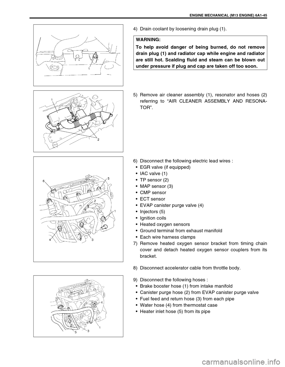
4) Drain coolant by loosening drain plug (1).
5) Remove air cleaner assembly (1), resonator and hoses (2)
referring to “AIR CLEANER ASSEMBLY AND RESONA-
TOR”.
6) Disconnect the following electric lead wires :
EGR valve (if equipped)
IAC valve (1)
TP sensor (2)
MAP sensor (3)
CMP sensor
ECT sensor
EVAP canister purge valve (4)
Injectors (5)
Ignition coils
Heated oxygen sensors
Ground terminal from exhaust manifold
Each wire harness clamps
7) Remove heated oxygen sensor bracket from timing chain
cover and detach heated oxygen sensor couplers from its
bracket.
8) Disconnect accelerator cable from throttle body.
9) Disconnect the following hoses :
Brake booster hose (1) from intake manifold
Canister purge hose (2) from EVAP canister purge valve
Fuel feed and return hose (3) from each pipe
Water hose (4) from thermostat case
Heater inlet hose (5) from its pipe WARNING:
To help avoid danger of being burned, do not remove
drain plug (1) and radiator cap while engine and radiator
are still hot. Scalding fluid and steam can be blown out
under pressure if plug and cap are taken off too soon.
Page 570 of 698
ENGINE MECHANICAL (M13 ENGINE) 6A1-69
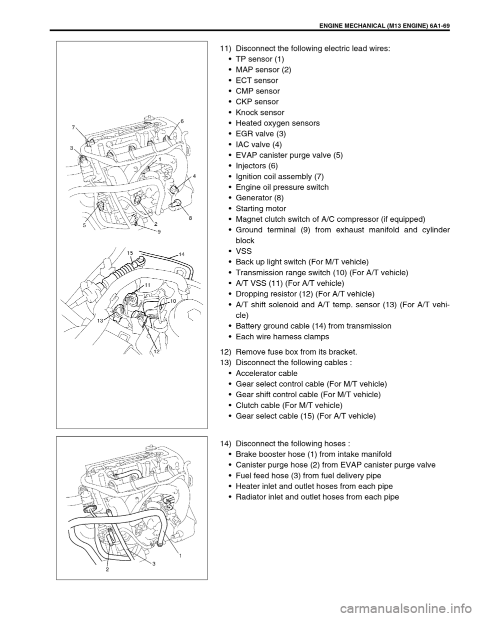
11) Disconnect the following electric lead wires:
TP sensor (1)
MAP sensor (2)
ECT sensor
CMP sensor
CKP sensor
Knock sensor
Heated oxygen sensors
EGR valve (3)
IAC valve (4)
EVAP canister purge valve (5)
Injectors (6)
Ignition coil assembly (7)
Engine oil pressure switch
Generator (8)
Starting motor
Magnet clutch switch of A/C compressor (if equipped)
Ground terminal (9) from exhaust manifold and cylinder
block
VSS
Back up light switch (For M/T vehicle)
Transmission range switch (10) (For A/T vehicle)
A/T VSS (11) (For A/T vehicle)
Dropping resistor (12) (For A/T vehicle)
A/T shift solenoid and A/T temp. sensor (13) (For A/T vehi-
cle)
Battery ground cable (14) from transmission
Each wire harness clamps
12) Remove fuse box from its bracket.
13) Disconnect the following cables :
Accelerator cable
Gear select control cable (For M/T vehicle)
Gear shift control cable (For M/T vehicle)
Clutch cable (For M/T vehicle)
Gear select cable (15) (For A/T vehicle)
14) Disconnect the following hoses :
Brake booster hose (1) from intake manifold
Canister purge hose (2) from EVAP canister purge valve
Fuel feed hose (3) from fuel delivery pipe
Heater inlet and outlet hoses from each pipe
Radiator inlet and outlet hoses from each pipe
Page 593 of 698
6B-4 ENGINE COOLING
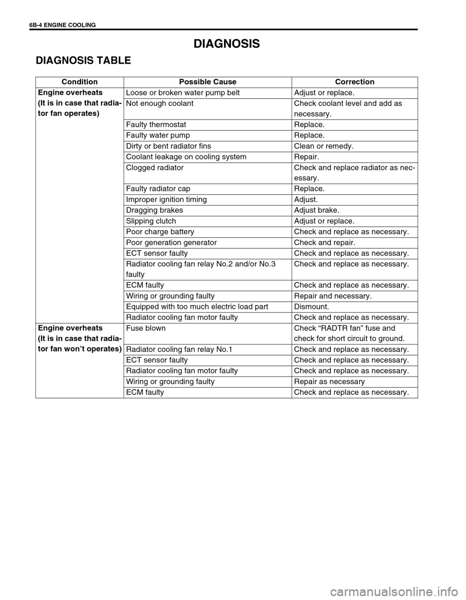
DIAGNOSIS
DIAGNOSIS TABLE
Condition Possible Cause Correction
Engine overheats
(It is in case that radia-
tor fan operates)Loose or broken water pump belt Adjust or replace.
Not enough coolant Check coolant level and add as
necessary.
Faulty thermostat Replace.
Faulty water pump Replace.
Dirty or bent radiator fins Clean or remedy.
Coolant leakage on cooling system Repair.
Clogged radiator Check and replace radiator as nec-
essary.
Faulty radiator cap Replace.
Improper ignition timing Adjust.
Dragging brakes Adjust brake.
Slipping clutch Adjust or replace.
Poor charge battery Check and replace as necessary.
Poor generation generator Check and repair.
ECT sensor faulty Check and replace as necessary.
Radiator cooling fan relay No.2 and/or No.3
faultyCheck and replace as necessary.
ECM faulty Check and replace as necessary.
Wiring or grounding faulty Repair and necessary.
Equipped with too much electric load part Dismount.
Radiator cooling fan motor faulty Check and replace as necessary.
Engine overheats
(It is in case that radia-
tor fan won’t operates)Fuse blown Check “RADTR fan” fuse and
check for short circuit to ground.
Radiator cooling fan relay No.1 Check and replace as necessary.
ECT sensor faulty Check and replace as necessary.
Radiator cooling fan motor faulty Check and replace as necessary.
Wiring or grounding faulty Repair as necessary
ECM faulty Check and replace as necessary.
Page 608 of 698
ENGINE FUEL 6C-1
6F1
6F2
6G
6C
6K
7A
7A1
7B1
7C1
7D
7E
7F
8A
8B
8C
8D
8E
9
10
10A
10B
SECTION 6C
ENGINE FUEL
CONTENTS
GENERAL DESCRIPTION .............................. 6C-1
ON-VEHICLE SERVICE .................................. 6C-2
COMPONENTS ........................................... 6C-2
PRECAUTIONS ........................................... 6C-3
FUEL LINES ................................................. 6C-4
FUEL PIPE ................................................... 6C-4
FUEL FILLER CAP ...................................... 6C-5FUEL TANK INLET VALVE ......................... 6C-6
FUEL TANK ................................................. 6C-7
FUEL PUMP ASSEMBLY .......................... 6C-10
DISASSEMBLY AND REASSEMBLY .... 6C-12
SPECIAL TOOL ............................................ 6C-14
TIGHTENING TORQUE SPECIFICATION.... 6C-14
GENERAL DESCRIPTION
The main components of the fuel system are fuel tank, fuel pump assembly (with fuel filter, fuel level gauge, fuel
pressure regulator and tank pressure control valve), fuel/vapor separator fuel feed line and fuel vapor line.
For the details of fuel flow and fuel vapor flow, refer to “GENERAL DESCRIPTION” in Section 6E. WARNING:
For vehicles equipped with Supplemental Restraint (Air Bag) System:
Service on and around the air bag system components or wiring must be performed only by an
authorized SUZUKI dealer. Refer to “Air Bag System Components and Wiring Location View” under
“General Description” in air bag system section in order to confirm whether you are performing ser-
vice on or near the air bag system components or wiring. Please observe all WARNINGS and “Ser-
vice Precautions” under “On-Vehicle Service” in air bag system section before performing service
on or around the air bag system components or wiring. Failure to follow WARNINGS could result in
unintentional activation of the system or could render the system inoperative. Either of these two
conditions may result in severe injury.
Technical service work must be started at least 90 seconds after the ignition switch is turned to the
“LOCK” position and the negative cable is disconnected from the battery. Otherwise, the system
may be activated by reserve energy in the Sensing and Diagnostic Module (SDM).
CAUTION:
The engine of this vehicle requires the use of unleaded fuel only. Use of leaded and/or low lead fuel
can result in engine damage and reduce the effectiveness of the emission control system.
Page 612 of 698
ENGINE FUEL 6C-5
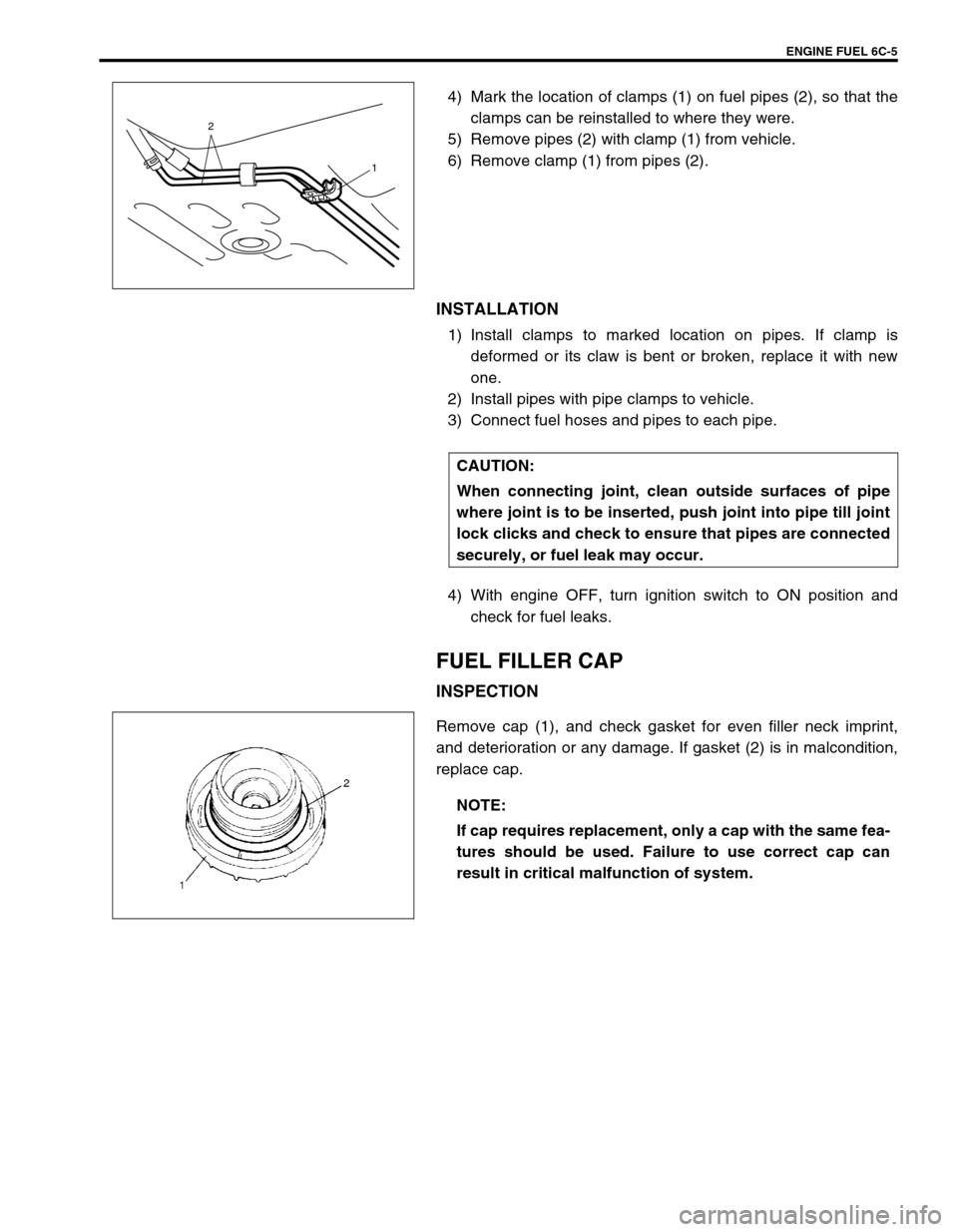
4) Mark the location of clamps (1) on fuel pipes (2), so that the
clamps can be reinstalled to where they were.
5) Remove pipes (2) with clamp (1) from vehicle.
6) Remove clamp (1) from pipes (2).
INSTALLATION
1) Install clamps to marked location on pipes. If clamp is
deformed or its claw is bent or broken, replace it with new
one.
2) Install pipes with pipe clamps to vehicle.
3) Connect fuel hoses and pipes to each pipe.
4) With engine OFF, turn ignition switch to ON position and
check for fuel leaks.
FUEL FILLER CAP
INSPECTION
Remove cap (1), and check gasket for even filler neck imprint,
and deterioration or any damage. If gasket (2) is in malcondition,
replace cap.
2
1
CAUTION:
When connecting joint, clean outside surfaces of pipe
where joint is to be inserted, push joint into pipe till joint
lock clicks and check to ensure that pipes are connected
securely, or fuel leak may occur.
NOTE:
If cap requires replacement, only a cap with the same fea-
tures should be used. Failure to use correct cap can
result in critical malfunction of system.
Page 617 of 698

6C-10 ENGINE FUEL
5) Connect fuel feed hose (1) and vapor hose (2) to each pipe
as shown in figure and clamp them securely.
6) Connect negative cable at battery.
With engine OFF, turn ignition switch to ON position and
check for fuel leaks.
FUEL PUMP ASSEMBLY
REMOVAL
1) Remove fuel tank from vehicle. Refer to “FUEL TANK”.
2) Disconnect fuel breather hose (1), fuel vapor hose (2) and
pipes from fuel pump assembly.
When disconnecting joint of fuel feed line (3) from pipe,
unlock joint by inserting special tool between pipe and joint
lock first.
Special tool
(A) : 09919-47020 CAUTION:
When connecting joint, clean outside surfaces of pipe
where joint is to be inserted, push joint into pipe till
joint lock clicks and check to ensure that pipes are
connected securely, or fuel leak may occur.
Never let the fuel hoses touch the ABS sensor harness
(if equipped).
WARNING:
Refer to the PRECAUTIONS at the beginning of ON-VEHI-
CLE SERVICE.
1
23
Page 622 of 698

ENGINE AND EMISSION CONTROL SYSTEM 6E1-1
6F1
6F2
6G
6H
6E1
7A
7A1
7B1
7C1
7D
7E
7F
8A
8B
8C
8D
8E
9
10
10A
10B
SECTION 6E1
ENGINE AND EMISSION CONTROL SYSTEM
CONTENTS
GENERAL DESCRIPTION ............................ 6E1-2
AIR INTAKE SYSTEM ............................... 6E1-5
FUEL DELIVERY SYSTEM ....................... 6E1-6
FUEL PUMP ........................................... 6E1-6
ELECTRONIC CONTROL SYSTEM .......... 6E1-7
ENGINE & EMISSION CONTROL
INPUT/OUTPUT TABLE ........................ 6E1-8
ECM INPUT/OUTPUT CIRCUIT
DIAGRAM............................................... 6E1-9
ECM TERMINAL ARRANGEMENT
TABLE .................................................. 6E1-13
ON-VEHICLE SERVICE .............................. 6E1-15
ACCELERATOR CABLE
ADJUSTMENT ..................................... 6E1-15
IDLE SPEED/IDLE AIR CONTROL
(IAC) DUTY INSPECTION ................... 6E1-15
IDLE MIXTURE INSPECTION /
ADJUSTMENT (VEHICLE WITHOUT
HEATED OXYGEN SENSOR) ............. 6E1-17
AIR INTAKE SYSTEM ............................. 6E1-18
THROTTLE BODY ............................... 6E1-18IDLE AIR CONTROL VALVE (IAC
VALVE) ................................................ 6E1-20
FUEL DELIVERY SYSTEM ..................... 6E1-21
FUEL PRESSURE INSPECTION ........ 6E1-21
FUEL PUMP WITH PRESSURE
REGULATOR ....................................... 6E1-22
FUEL INJECTOR ................................. 6E1-23
ELECTRONIC CONTROL SYSTEM ....... 6E1-27
ENGINE CONTROL MODULE
(ECM) ................................................... 6E1-27
MANIFOLD ABSOLUTE PRESSURE
SENSOR (MAP SENSOR)................... 6E1-27
THROTTLE POSITION SENSOR (TP
SENSOR) ............................................. 6E1-28
INTAKE AIR TEMPERATURE
SENSOR (IAT SENSOR) ..................... 6E1-29
ENGINE COOLANT TEMPERATURE
SENSOR (ECT SENSOR) ................... 6E1-30
HEATED OXYGEN SENSOR (HO2S-1
AND HO2S-2) ...................................... 6E1-31
CAMSHAFT POSITION SENSOR ....... 6E1-32 WARNING:
For vehicles equipped with Supplemental Restraint (Air Bag) System :
Service on and around the air bag system components or wiring must be performed only by an
authorized SUZUKI dealer. Refer to “Air Bag System Components and Wiring Location View” under
“General Description” in air bag system section in order to confirm whether you are performing ser-
vice on or near the air bag system components or wiring. Please observe all WARNINGS and “Ser-
vice Precautions” under “On-Vehicle Service” in air bag system section before performing service
on or around the air bag system components or wiring. Failure to follow WARNINGS could result in
unintentional activation of the system or could render the system inoperative. Either of these two
conditions may result in severe injury.
Technical service work must be started at least 90 seconds after the ignition switch is turned to the
“LOCK” position and the negative cable is disconnected from the battery. Otherwise, the system
may be activated by reserve energy in the Sensing and Diagnostic Module (SDM).
NOTE:
Whether the following system (parts) are used in the particular vehicle or not depends on vehicle
specifications. Be sure to bear this in mind when performing service work.
EGR valve
Heated oxygen sensor(s) or CO adjusting resistor
Three way catalytic converter
Immobilizer indicator lamp
Knock sensor