Page 609 of 698
6C-2 ENGINE FUEL
ON-VEHICLE SERVICE
COMPONENTS
1. Fuel tank 7. Fuel vapor line 13. Fuel filler hose clamp screw 19. Fuel pressure regulator
2. Fuel pump assembly 8. EVAP canister 14. Tank cover 20. Fuel pump
3. Breather hose 9. Delivery pipe 15. Fuel filler bracket screw 21. Fuel filter assembly
4. Fuel filler cap 10. Fuel/vapor separator 16. Fuel filler bracket nut 22. Fuel level gauge (Fuel sender gauge)
5. Fuel feed line 11. Fuel pump bolt (6 pcs.) 17. Gasket Do not reuse.
6. Wire harness for fuel pump 12. Fuel tank bolt (4 pcs.) 18. O-ring Tightening torque
Page 616 of 698

ENGINE FUEL 6C-9
FUEL TANK PURGING PROCEDURE
The following procedure is used for purging fuel tank.
1) After removing fuel tank, remove all hoses, pipes, fuel pump
assembly from fuel tank.
2) Drain all remaining fuel from tank.
3) Move tank to flushing area.
4) Fill tank with warm water or tap water, and agitate vigorously
and drain. Repeat this washing until inside of tank is clean.
Replace tank if its inside is rusty.
5) Completely flush out remaining water after washing.
INSTALLATION
1) If parts have been removed from fuel tank, install them
before installing fuel tank to vehicle.
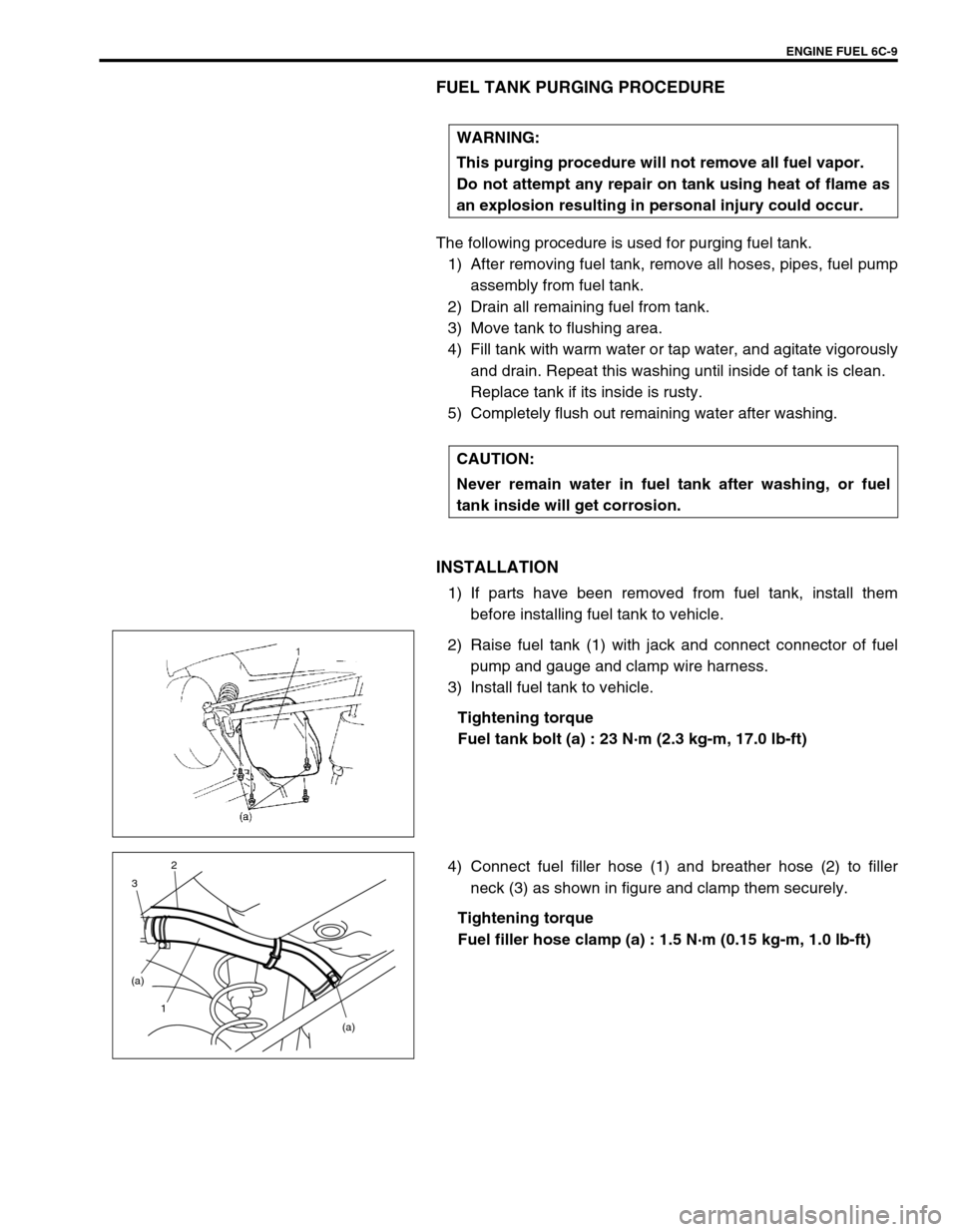
2) Raise fuel tank (1) with jack and connect connector of fuel
pump and gauge and clamp wire harness.
3) Install fuel tank to vehicle.
Tightening torque
Fuel tank bolt (a) : 23 N·m (2.3 kg-m, 17.0 lb-ft)
4) Connect fuel filler hose (1) and breather hose (2) to filler
neck (3) as shown in figure and clamp them securely.
Tightening torque
Fuel filler hose clamp (a) : 1.5 N·m (0.15 kg-m, 1.0 lb-ft) WARNING:
This purging procedure will not remove all fuel vapor.
Do not attempt any repair on tank using heat of flame as
an explosion resulting in personal injury could occur.
CAUTION:
Never remain water in fuel tank after washing, or fuel
tank inside will get corrosion.
(a) (a)
1 32
Page 620 of 698
ENGINE FUEL 6C-13
INSTALLATION
1) Clean mating surfaces of fuel pump assembly (1) and fuel
tank.
2) Put plate (2) on fuel pump assembly (1) by matching the pro-
trusion of fuel pump assembly (3) to plate hole (4) as shown.
3) Install new gasket (2) and fuel pump assembly (1) with plate
(3) to fuel tank.
Tightening torque
Fuel pump assembly bolts (a) : 10 N·m (1.0 kg-m, 7.5 lb-ft)
4) Connect fuel breather hose (1), fuel vapor hose (2) and fuel
feed line (3) (pipe joint) to fuel pump assembly.
5) Install fuel tank (1) to vehicle. Refer to “FUEL TANK” in this
section.
3 2
4 43
1
3
1
2
(a)
CAUTION:
When connecting joint, clean outside surface of pipe
where joint is to be inserted, push joint into pipe till joint
lock clicks and check to ensure that pipes are connected
securely, or fuel leak may occur.1
23
Page 621 of 698
6C-14 ENGINE FUEL
SPECIAL TOOL
TIGHTENING TORQUE SPECIFICATION
09917-47010 09919-47020
Vacuum pump gauge Quick joint remover
Fastening partTightening torque
Nm kg-m lb-ft
Fuel tank bolts 23 2.3 17
Fuel filler hose clamps 1.5 0.15 1
Fuel pump assembly bolts 10 1 7.5
Page 623 of 698

6E1-2 ENGINE AND EMISSION CONTROL SYSTEM
CRANKSHAFT POSITION SENSOR .. 6E1-32
VEHICLE SPEED SENSOR (VSS) ...... 6E1-33
FUEL LEVEL SENSOR (GAUGE) ....... 6E1-33
KNOCK SENSOR (IF EQUIPPED) ...... 6E1-33
MAIN RELAY, FUEL PUMP RELAY
AND RADIATOR FAN RELAY NO.1.... 6E1-33
FUEL CUT OPERATION ..................... 6E1-34
RADIATOR FAN CONTROL
SYSTEM .............................................. 6E1-34
RADIATOR FAN RELAY NO. 2 AND
NO.3 ..................................................... 6E1-34OUTPUT SIGNALS OF THROTTLE
VALVE OPENING AND ENGINE
COOLANT TEMP. (VEHICLE WITH
A/T ONLY) ........................................... 6E1-36
EMISSION CONTROL SYSTEM ............. 6E1-36
EGR SYSTEM ..................................... 6E1-36
EVAPORATIVE EMISSION CONTROL
SYSTEM .............................................. 6E1-37
PCV SYSTEM ...................................... 6E1-39
SPECIAL TOOL .......................................... 6E1-40
TIGHTENING TORQUE SPECIFICATION . 6E1-41
GENERAL DESCRIPTION
The engine and emission control system is divided into 4 major sub-systems : air intake system, fuel delivery
system, electronic control system and emission control system.
Air intake system includes air cleaner, throttle body, IAC valve and intake manifold.
Fuel delivery system includes fuel pump, delivery pipe, fuel pressure regulator, etc. Electronic control system
includes ECM, various sensors and controlled devices.
Emission control system includes EGR, EVAP and PCV system.
Page 639 of 698
6E1-18 ENGINE AND EMISSION CONTROL SYSTEM
AIR INTAKE SYSTEM
THROTTLE BODY
ON-VEHICLE INSPECTION
Check that throttle valve lever (1) moves smoothly.
REMOVAL
1) Disconnect negative cable at battery.
2) Drain cooling system.
3) Disconnect accelerator cable (1) from throttle valve lever.
4) Disconnect IAT sensor connector and remove air cleaner
assembly with air cleaner outlet hose.
1. Throttle body 4. Gasket 7. TP sensor screws
2. Throttle stop screw 5. Idle air control valve Tightening torque
3. TP sensor 6. IAC valve screws Do not reuse.
Page 641 of 698

6E1-20 ENGINE AND EMISSION CONTROL SYSTEM
3) Install throttle body (1) to intake manifold.
4) Connect connector to TP sensor (2) and IAC valve (3)
securely.
5) Connect accelerator cable and adjust cable play to specifica-
tion.
6) Install air cleaner assembly with air cleaner outlet hose and
connect IAT sensor connector.
7) Refill cooling system.
8) Connect negative cable at battery.
IDLE AIR CONTROL VALVE (IAC VALVE)
REMOVAL
1) Remove throttle body from intake manifold referring to
“Throttle Body Removal” section.
2) Remove IAC valve from throttle body.
INSPECTION
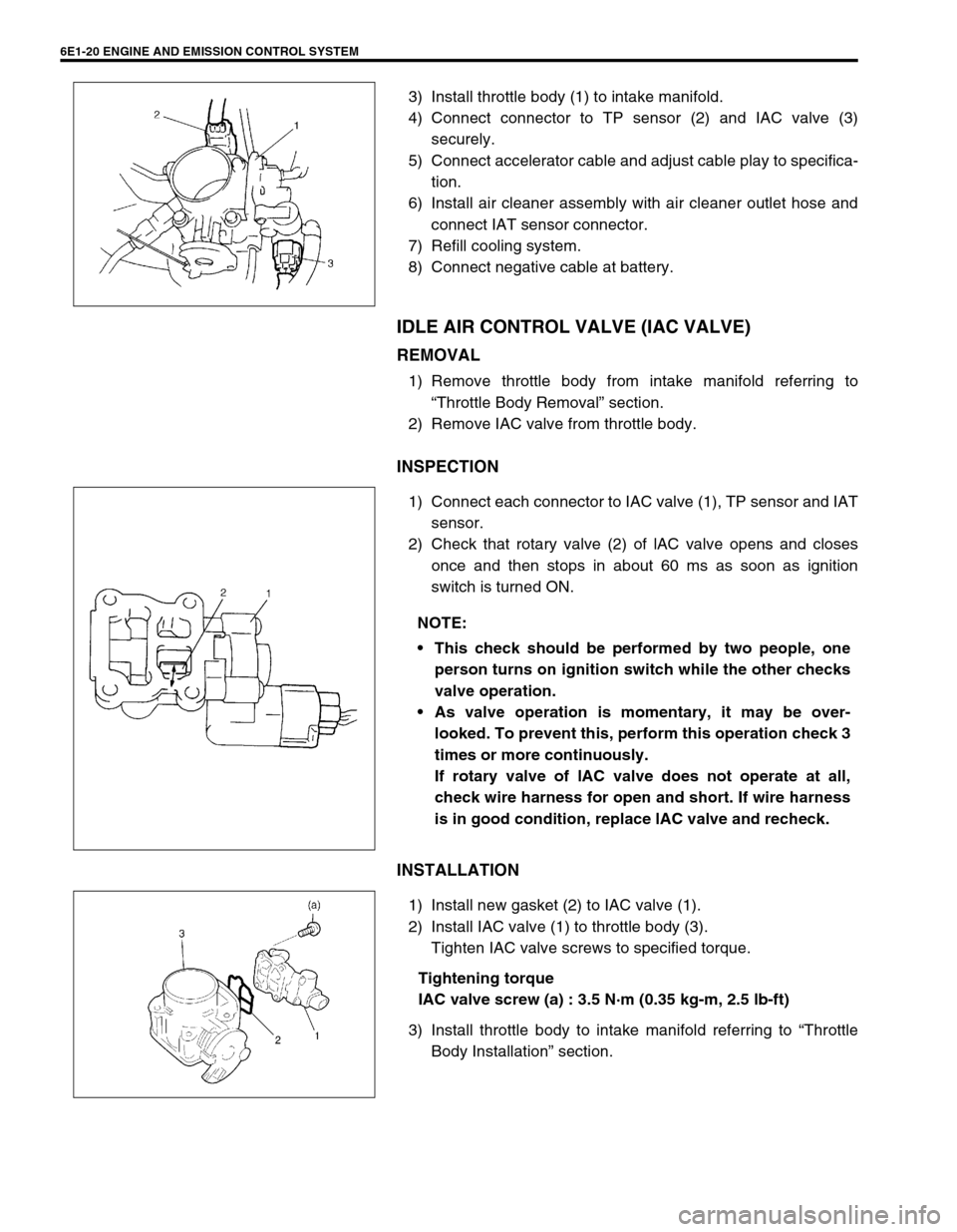
1) Connect each connector to IAC valve (1), TP sensor and IAT
sensor.
2) Check that rotary valve (2) of lAC valve opens and closes
once and then stops in about 60 ms as soon as ignition
switch is turned ON.
INSTALLATION
1) Install new gasket (2) to IAC valve (1).
2) Install IAC valve (1) to throttle body (3).
Tighten IAC valve screws to specified torque.
Tightening torque
IAC valve screw (a) : 3.5 N·m (0.35 kg-m, 2.5 lb-ft)
3) Install throttle body to intake manifold referring to “Throttle
Body Installation” section.
NOTE:
This check should be performed by two people, one
person turns on ignition switch while the other checks
valve operation.
As valve operation is momentary, it may be over-
looked. To prevent this, perform this operation check 3
times or more continuously.
If rotary valve of lAC valve does not operate at all,
check wire harness for open and short. If wire harness
is in good condition, replace lAC valve and recheck.
Page 647 of 698
6E1-26 ENGINE AND EMISSION CONTROL SYSTEM
INSTALLATION
For installation, reverse removal procedure and note following
precautions.
Replace injector O-ring (1) with new one using care not to
damage it.
Check if cushion (2) is scored or damaged. If it is, replace
with new one.
Apply thin coat of fuel to O-rings (1) and then install injectors
(3) into delivery pipe (4) and intake manifold.
Make sure that injectors (3) rotate smoothly (6). If not, proba-
ble cause is incorrect installation of O-ring (1). Replace O-
ring (1) with new one.
Tighten delivery pipe bolts (5) and make sure that injectors
(3) rotate smoothly (6).
Tightening torque
Delivery pipe bolts (a) : 28 N·m (2.8 kg-m, 20.5 lb-ft)
After installation, with engine “OFF” and ignition switch “ON”,
check for fuel leaks around fuel line connection.5, (a)
4
1
3 2