Page 649 of 698
6E1-28 ENGINE AND EMISSION CONTROL SYSTEM
THROTTLE POSITION SENSOR (TP SENSOR)
INSPECTION
1) Disconnect negative cable at battery and connector from IAT
sensor.
2) Remove air cleaner assembly with air cleaner outlet hose
and disconnect TP sensor connector.
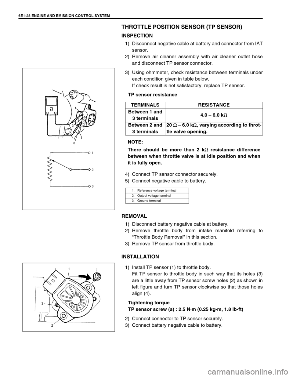
3) Using ohmmeter, check resistance between terminals under
each condition given in table below.
If check result is not satisfactory, replace TP sensor.
TP sensor resistance
4) Connect TP sensor connector securely.
5) Connect negative cable to battery.
REMOVAL
1) Disconnect battery negative cable at battery.
2) Remove throttle body from intake manifold referring to
“Throttle Body Removal” in this section.
3) Remove TP sensor from throttle body.
INSTALLATION
1) Install TP sensor (1) to throttle body.
Fit TP sensor to throttle body in such way that its holes (3)
are a little away from TP sensor screw holes (2) as shown in
left figure and turn TP sensor clockwise so that those holes
align (4).
Tightening torque
TP sensor screw (a) : 2.5 N·m (0.25 kg-m, 1.8 lb-ft)
2) Connect connector to TP sensor securely.
3) Connect battery negative cable to battery.TERMINALS RESISTANCE
Between 1 and
3 terminals4.0 – 6.0 k
Ω
Between 2 and
3 terminals20
Ω – 6.0 k
Ω, varying according to throt-
tle valve opening.
NOTE:
There should be more than 2 k
Ω resistance difference
between when throttle valve is at idle position and when
it is fully open.
1. Reference voltage terminal
2. Output voltage terminal
3. Ground terminal
Page 651 of 698
6E1-30 ENGINE AND EMISSION CONTROL SYSTEM
ENGINE COOLANT TEMPERATURE SENSOR (ECT
SENSOR)
REMOVAL
1) Disconnect battery negative cable at battery.
2) Drain coolant referring to Section 6B.
3) Remove air intake pipe.
4) Disconnect connector from ECT sensor.
5) Remove ECT sensor (1) from thermostat case.
INSPECTION
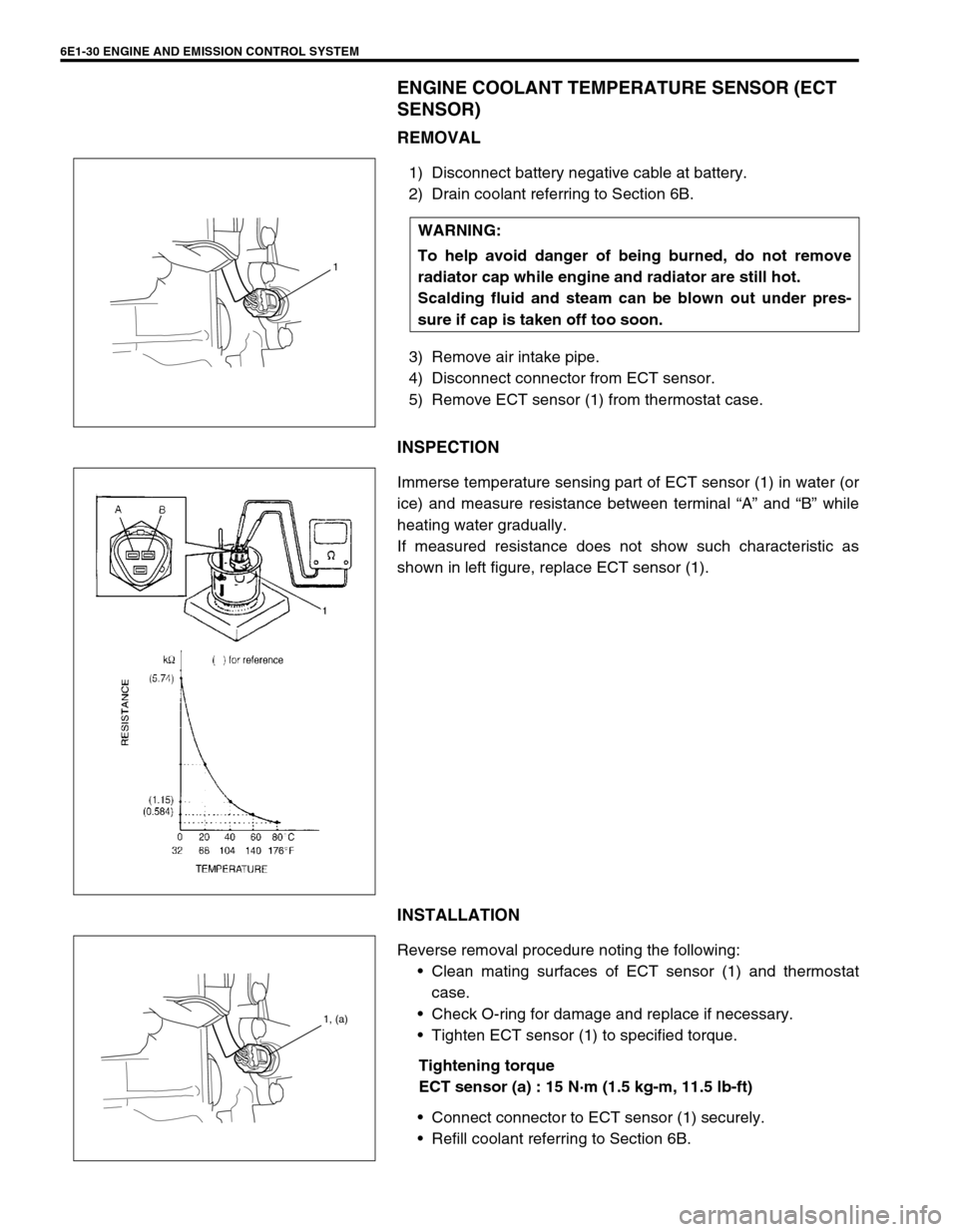
Immerse temperature sensing part of ECT sensor (1) in water (or
ice) and measure resistance between terminal “A” and “B” while
heating water gradually.
If measured resistance does not show such characteristic as
shown in left figure, replace ECT sensor (1).
INSTALLATION
Reverse removal procedure noting the following:
Clean mating surfaces of ECT sensor (1) and thermostat
case.
Check O-ring for damage and replace if necessary.
Tighten ECT sensor (1) to specified torque.
Tightening torque
ECT sensor (a) : 15 N·m (1.5 kg-m, 11.5 lb-ft)
Connect connector to ECT sensor (1) securely.
Refill coolant referring to Section 6B. WARNING:
To help avoid danger of being burned, do not remove
radiator cap while engine and radiator are still hot.
Scalding fluid and steam can be blown out under pres-
sure if cap is taken off too soon.
1
1, (a)
Page 652 of 698
ENGINE AND EMISSION CONTROL SYSTEM 6E1-31
HEATED OXYGEN SENSOR (HO2S-1 AND HO2S-2)
OXYGEN SENSOR HEATER INSPECTION
1) Disconnect sensor connector.
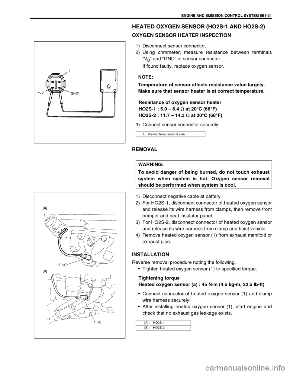
2) Using ohmmeter, measure resistance between terminals
“V
B” and “GND” of sensor connector.
If found faulty, replace oxygen sensor.
Resistance of oxygen sensor heater
HO2S-1 : 5.0 – 6.4
Ω at 20°C (68°F)
HO2S-2 : 11.7 – 14.3
Ω at 20°C (68°F)
3) Connect sensor connector securely.
REMOVAL
1) Disconnect negative cable at battery.
2) For HO2S-1, disconnect connector of heated oxygen sensor
and release its wire harness from clamps, then remove front
bumper and heat insulator panel.
3) For HO2S-2, disconnect connector of heated oxygen sensor
and release its wire harness from clamp and hoist vehicle.
4) Remove heated oxygen sensor (1) from exhaust manifold or
exhaust pipe.
INSTALLATION
Reverse removal procedure noting the following.
Tighten heated oxygen sensor (1) to specified torque.
Tightening torque
Heated oxygen sensor (a) : 45 N·m (4.5 kg-m, 32.5 lb-ft)
Connect connector of heated oxygen sensor (1) and clamp
wire harness securely.
After installing heated oxygen sensor (1), start engine and
check that no exhaust gas leakage exists. NOTE:
Temperature of sensor affects resistance value largely.
Make sure that sensor heater is at correct temperature.
1. Viewed from terminal side
WARNING:
To avoid danger of being burned, do not touch exhaust
system when system is hot. Oxygen sensor removal
should be performed when system is cool.
[A] : HO2S-1
[B] : HO2S-2
Page 653 of 698
6E1-32 ENGINE AND EMISSION CONTROL SYSTEM
CAMSHAFT POSITION SENSOR
INSPECTION
Check camshaft position sensor referring to DTC P0340 (No.15)
Diag. Flow Table in Section 6. If malfunction is found, replace.
REMOVAL
1) Disconnect negative cable at battery.
2) Disconnect connector from camshaft position sensor.
3) Remove camshaft position sensor from cylinder head.
INSTALLATION
1) Check that O-ring is free from damage.
2) Check that camshaft position sensor and signal rotor teeth
are free from any metal particles and damage.
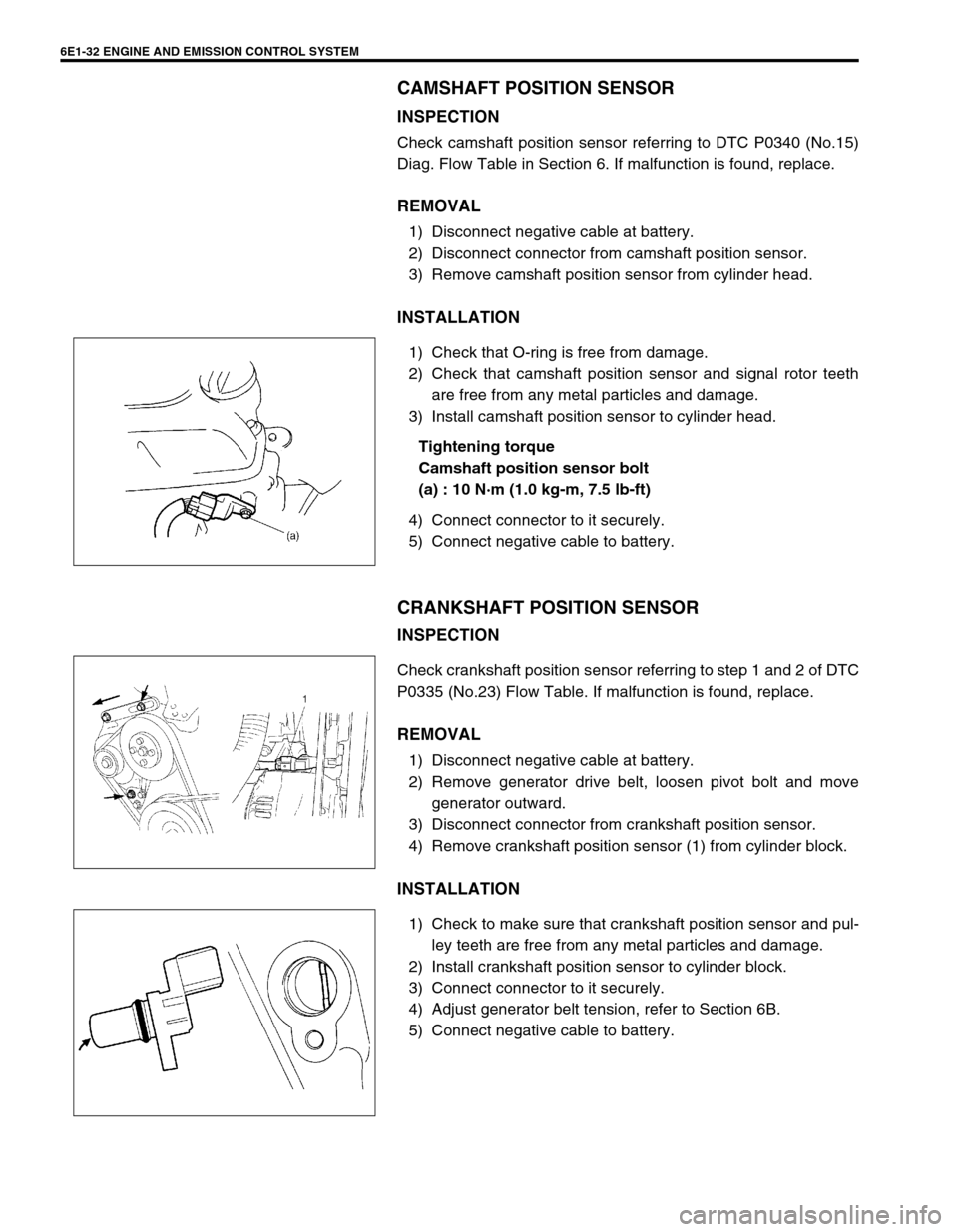
3) Install camshaft position sensor to cylinder head.
Tightening torque
Camshaft position sensor bolt
(a) : 10 N·m (1.0 kg-m, 7.5 lb-ft)
4) Connect connector to it securely.
5) Connect negative cable to battery.
CRANKSHAFT POSITION SENSOR
INSPECTION
Check crankshaft position sensor referring to step 1 and 2 of DTC
P0335 (No.23) Flow Table. If malfunction is found, replace.
REMOVAL
1) Disconnect negative cable at battery.
2) Remove generator drive belt, loosen pivot bolt and move
generator outward.
3) Disconnect connector from crankshaft position sensor.
4) Remove crankshaft position sensor (1) from cylinder block.
INSTALLATION
1) Check to make sure that crankshaft position sensor and pul-
ley teeth are free from any metal particles and damage.
2) Install crankshaft position sensor to cylinder block.
3) Connect connector to it securely.
4) Adjust generator belt tension, refer to Section 6B.
5) Connect negative cable to battery.
Page 662 of 698
ENGINE AND EMISSION CONTROL SYSTEM 6E1-41
TIGHTENING TORQUE SPECIFICATION
09931-76030
16/14 pin DLC cable
NOTE:
“A”: This kit includes the following items.
1. Tool body & washer, 2. Body plug, 3. Body attachment-1, 4. Holder, 5. Return hose & clamp,
6. Body attachment-2 & washer, 7. Hose attachment-1, 8. Hose attachment-2
“B”: This kit includes the following items.
1. Storage case, 2. Operator’s manual, 3. Tech 1A, 4. DLC cable (14/26 pin, 09931-76040),
5. Test lead/probe, 6. Power source cable, 7. DLC cable adaptor, 8. Self-test adaptor
Fastening partTightening torque
Nm kg-m lb-ft
TP sensor mounting screw 2.5 0.25 1.8
IAC valve 3.5 0.35 2.5
ECT sensor 15 1.5 11.5
Heated oxygen sensor-1 and -2 45 4.5 32.5
Camshaft position sensor 10 1.0 7.5
Page 669 of 698
IGNITION SYSTEM (ELECTRONIC IGNITION SYSTEM 6F1-7
6) Install spark plugs and torque them to specification.
Tightening torque
Spark plug : 25 N·m (2.5 kg-m, 18.0 lb-ft)
7) Install ignition coil assemblies referring to IGNITION COIL
ASSEMBLY in this section.
8) Install high-tension cords securely by gripping their caps.
9) Install cylinder head upper cover and air intake pipe.
IGNITION COIL ASSEMBLY
(INCLUDING IGNITOR)
Inspection
1) Disconnect negative cable at battery.
2) Remove air intake pipe and cylinder head upper cover.
3) Disconnect ignition coil coupler.
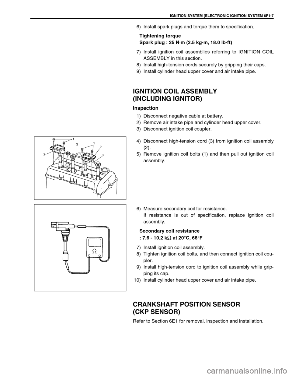
4) Disconnect high-tension cord (3) from ignition coil assembly
(2).
5) Remove ignition coil bolts (1) and then pull out ignition coil
assembly.
6) Measure secondary coil for resistance.
If resistance is out of specification, replace ignition coil
assembly.
Secondary coil resistance
: 7.6 - 10.2 k
Ω at 20°C, 68°F
7) Install ignition coil assembly.
8) Tighten ignition coil bolts, and then connect ignition coil cou-
pler.
9) Install high-tension cord to ignition coil assembly while grip-
ping its cap.
10) Install cylinder head upper cover and air intake pipe.
CRANKSHAFT POSITION SENSOR
(CKP SENSOR)
Refer to Section 6E1 for removal, inspection and installation.
Page 675 of 698
CRANKING SYSTEM 6G-3
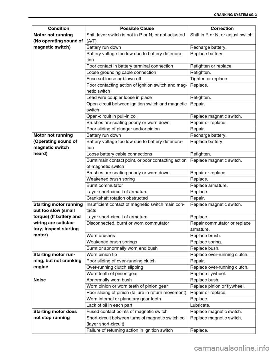
Condition Possible Cause Correction
Motor not running
(No operating sound of
magnetic switch)Shift lever switch is not in P or N, or not adjusted
(A/T)Shift in P or N, or adjust switch.
Battery run down Recharge battery.
Battery voltage too low due to battery deteriora-
tionReplace battery.
Poor contact in battery terminal connection Retighten or replace.
Loose grounding cable connection Retighten.
Fuse set loose or blown off Tighten or replace.
Poor contacting action of ignition switch and mag-
netic switchReplace.
Lead wire coupler loose in place Retighten.
Open-circuit between ignition switch and magnetic
switchRepair.
Open-circuit in pull-in coil Replace magnetic switch.
Brushes are seating poorly or worn down Repair or replace.
Poor sliding of plunger and/or pinion Repair.
Motor not running
(Operating sound of
magnetic switch
heard)Battery run down Recharge battery.
Battery voltage too low due to battery deteriora-
tionReplace battery.
Loose battery cable connections Retighten.
Burnt main contact point, or poor contacting action
of magnetic switchReplace magnetic switch.
Brushes are seating poorly or worn down Repair or replace.
Weakened brush spring Replace.
Burnt commutator Replace armature.
Layer short-circuit of armature Replace.
Crankshaft rotation obstructed Repair.
Starting motor running
but too slow (small
torque) (If battery and
wiring are satisfac-
tory, inspect starting
motor)Insufficient contact of magnetic switch main con-
tactsReplace magnetic switch.
Layer short-circuit of armature Replace.
Disconnected, burnt or worn commutator Repair commutator or replace
armature.
Worn brushes Replace brush.
Weakened brush springs Replace spring.
Burnt or abnormally worn end bush Replace bush.
Starting motor run-
ning, but not cranking
engineWorn pinion tip Replace over-running clutch.
Poor sliding of over-running clutch Repair.
Over-running clutch slipping Replace over-running clutch.
Worn teeth of pinion gear Replace flywheel.
Noise
Abnormally worn bush Replace bush.
Worn pinion or worn teeth of pinion gear Replace pinion or flywheel.
Poor sliding of pinion (failure in return movement) Repair or replace.
Worn internal or planetary gear teeth Replace.
Lack of oil in each part Lubricate.
Starting motor does
not stop runningFused contact points of magnetic switch Replace magnetic switch.
Short-circuit between turns of magnetic switch coil
(layer short-circuit)Replace magnetic switch.
Failure of returning action in ignition switch Replace.
Page 677 of 698
CRANKING SYSTEM 6G-5
NO-LOAD PERFORMANCE TEST
Connect battery and ammeter to starter as shown.
Check that starter rotates smoothly and steadily with pinion mov-
ing out. Check that ammeter indicates specified current.
Specified current (No-load performance test)
: 90 A MAX. at 11 V
ON-VEHICLE SERVICE
STARTING MOTOR
DISMOUNTING
1) Disconnect negative (–) battery lead at battery.
2) Disconnect magnetic switch lead wire (1) and battery cable (2) from starting motor terminals.
3) Remove starting motor mount bolt (3) and nut (4).
4) Remove starting motor (5).
REMOUNTING
Reverse the dismounting procedure.
Tightening torque
Starting motor battery cable nut (a) : 10 N·m (1.0 kg-m, 7.5 lb-ft)