2000 SUZUKI SWIFT oil control valve
[x] Cancel search: oil control valvePage 409 of 698

6-40 ENGINE GENERAL INFORMATION AND DIAGNOSIS
For TYPE B (For applicable mode, refer to NOTE in “ECM VOLTAGE VALUES TABLE”) G02 17 Power source for back-up 10 – 14 V Anytime
TERMINAL NO. CIRCUIT NORMAL VOLT-
AGECONDITION
C421Ground––
2Ground––
3Ground––
4 EVAP canister purge valve 10 – 14 V Ignition switch ON
5–– –
6 Idle air control valve 0 – 13 V At specified idle speed after engine warmed up
7 Heater of HO2S-1 (if equipped) 10 – 14 V Ignition switch ON
8 Fuel injector NO.4 10 – 14 V Ignition switch ON
9 Fuel injector NO.1 10 – 14 V Ignition switch ON
10 Sensor ground––
11 Camshaft position sensor 0 – 0.8 V and
4 – 6 VIgnition switch ON
12 Shield ground––
13 Heated oxygen sensor-1 (if equipped) Refer to DTC P0130 diag. flow table
CO adjusting resistor (if equipped)––
14 Engine coolant temp. sensor 0.55 - 0.95 V Ignition switch ON
Engine coolant temp. : 80°C (176°F)
15 Intake air temp. sensor 2.0 – 2.7 V Ignition switch ON
Intake air temp. : 20°C (68°F)
16 Throttle position sensor 0.2 – 1.0 V Ignition switch ON
Throttle valve at idle position
2.8 – 4.8 V Ignition switch ON
Throttle valve at full open position
17 EGR valve (stepper motor coil 3)
(if equipped)10 – 14 V Ignition switch ON
18 EGR valve (stepper motor coil 1)
(if equipped)10 – 14 V Ignition switch ON
19 Ignition coil #2––
20 Ignition coil #1––
21 Fuel injector NO.2 10 – 14 V Ignition switch ON
22 Power source for sensor 4.75 – 5.25 V Ignition switch ON
23 Crankshaft position sensor––
24–– –
25 knock sensor (if equipped) 2.1 – 2.9 V Ignition switch ON
26 Manifold absolute pressure sensor 3.3 – 4.0 V Ignition switch ON
Barometric pressure : 100 kPa (760 mmHg)
27–– –
28 EGR valve (stepper motor coil 4)
(if equipped)10 – 14 V Ignition switch ON
29 EGR valve (stepper motor coil 2)
(if equipped)10 – 14 V Ignition switch ON
30 A/C triple pressure switch 10 – 14 V A/C not operated
31 Fuel injector NO.3 10 – 14 V Ignition switch ON
TERMINAL
NO.CIRCUIT NORMAL
VOLTAGECONDITION
Page 412 of 698

ENGINE GENERAL INFORMATION AND DIAGNOSIS 6-43
Resistance Check
1) Disconnect ECM couplers from ECM with ignition switch
OFF.
2) Check resistance between each terminal of connectors dis-
connected.
TERMINAL RESISTANCE TABLE
For TYPE A (Refer to NOTE in “ECM VOLTAGE VALUES TABLE” for applicable model) CAUTION:
Never touch terminals of ECM itself or connect voltmeter
or ohmmeter.
CAUTION:
Be sure to connect ohmmeter probe from wire harness
side of coupler.
Be sure to turn OFF ignition switch for this check.
Resistance in table below represents that when parts
temperature is 20°C (68°F).
1. ECM coupler disconnected
2. Ohmmeter
TERMINALS CIRCUIT STANDARD
RESISTANCE
C42-7 to G02-6 HO2S-1 heater (if equipped) 5.0 – 6.4 Ω
C41-4 to G02-6 HO2S-2 heater (if equipped) 12.0 – 14.3 Ω
C42-9 to C41-5/6 No.1 injector 11.3 – 13.8 Ω
C42-21 to C41-5/6 No.2 injector 11.3 – 13.8 Ω
C42-31 to C41-5/6 No.3 injector 11.3 – 13.8 Ω
C42-8 to C41-5/6 No.4 injector 11.3 – 13.8 Ω
C41-2 to C41-5/6 EGR valve (stepper motor coil 1) (if equipped) 20 – 24 Ω
C41-9 to C41-5/6 EGR valve (stepper motor coil 2) (if equipped) 20 – 24 Ω
C41-8 to C41-5/6 EGR valve (stepper motor coil 3) (if equipped) 20 – 24 Ω
C41-17 to C41-5/6 EGR valve (stepper motor coil 4) (if equipped) 20 – 24 Ω
C42-4 to C41-5/6 EVAP canister purge valve 30 – 34 Ω
C41-19 to G02-6 Fuel pump relay 56 – 146 Ω
C41-1 to Body ground A/C compressor clutch 3 – 5.5 Ω
C41-18 to C41-5/6 Radiator fan control relay No.1 56 – 146 Ω
C41-10 to G02-17 Main relay 56 – 146 Ω
C42-1 to Body ground Ground Continuity
C42-2 to Body ground Ground Continuity
C42-3 to Body ground Ground Continuity
Page 413 of 698

6-44 ENGINE GENERAL INFORMATION AND DIAGNOSIS
For TYPE B (Refer to NOTE in “ECM VOLTAGE VALUES TABLE” for applicable model.)
TERMINALS CIRCUIT STANDARD
RESISTANCE
C42-7 to C41-11 HO2S-1 heater (if equipped) 5.0 – 6.4 Ω
C41-4 to C41-11 HO2S-2 heater (if equipped) 12.0 – 14.3 Ω
C42-9 to C41-5/6 No.1 injector 11.3 – 13.8 Ω
C42-21 to C41-5/6 No.2 injector 11.3 – 13.8 Ω
C42-31 to C41-5/6 No.3 injector 11.3 – 13.8 Ω
C42-8 to C41-5/6 No.4 injector 11.3 – 13.8 Ω
C42-18 to C41-5/6 EGR valve (stepper motor coil 1) (if equipped) 20 – 24 Ω
C42-29 to C41-5/6 EGR valve (stepper motor coil 2) (if equipped) 20 – 24 Ω
C42-17 to C41-5/6 EGR valve (stepper motor coil 3) (if equipped) 20 – 24 Ω
C42-28 to C41-5/6 EGR valve (stepper motor coil 4) (if equipped) 20 – 24 Ω
C42-4 to C41-5/6 EVAP canister purge valve 30 – 34 Ω
C41-19 to G02-6 Fuel pump relay 56 – 146 Ω
C41-1 to Body ground A/C compressor clutch 3 – 5.5 Ω
C41-18 to C41-5/6 Radiator fan control relay No.1 56 – 146 Ω
C41-10 to C41-7 Main relay 56 – 146 Ω
C42-1 to Body ground Ground Continuity
C42-2 to Body ground Ground Continuity
C42-3 to Body ground Ground Continuity
Page 414 of 698

ENGINE GENERAL INFORMATION AND DIAGNOSIS 6-45
COMPONENT LOCATION
1. TP sensor 9. Radiator fan control relay No.3 17. ECM
2. MAP sensor 10. EVAP canister purge valve 18. Monitor connector
3. IAC valve 11. ECT sensor 19. VSS
4. IAT sensor 12. Ignition coil with igniter 20. Knock sensor (if equipped)
5. Radiator fan control relay No.1 13. HO2S-1 (if equipped) 21. CMP sensor
6. Main relay 14. HO2S-2 (if equipped) 22. EGR valve (if equipped)
7. Fuel pump relay 15. CKP sensor✱ : This figure shows left-hand steering vehicle, these parts are
installed at the other side for right-hand steering vehicle.
8. Radiator fan control relay No.2 16. TCM
1
3
24
518
6 7
20
19
8
9 1617
21
15
131214
10
22
11
Page 451 of 698

6-82 ENGINE GENERAL INFORMATION AND DIAGNOSIS
DTC CONFIRMATION PROCEDURE
1) Turn ignition switch OFF.
2) Clear DTC with ignition switch ON.
3) Check vehicle and environmental condition for :
–Altitude (barometric pressure) : 2400 m, 8000 ft or less (560 mmHg, 75 kPa or more)
–Ambient temp. : –10°C, 14°F or higher
–Intake air temp. : 70°C, 158°F or lower
–Engine coolant temp. : – 10 – 110°C, 14 – 230°F
4) Start engine and keep it at idle for 2 min. or more.
5) Check DTC in “DTC” mode and pending DTC in “ON BOARD TEST” or “PENDING DTC” mode.
6) If DTC is not detected at idle, consult usual driving based on information obtained in “Customer complaint
analysis” and “Freeze frame data check”.
INSPECTION
DTC DETECTING CONDITION POSSIBLE CAUSE
Engine under other than high revolution condition
Not on rough road
Engine speed changing rate (Below specified value)
Manifold absolute pressure changing rate (Below
specified value)
Throttle opening changing rate (Below specified
value)
Misfire rate per 200 or 1000 engine revolutions (how
much and how often crankshaft revolution speed
changes) is higher than specified valueEngine overheating
Vacuum leaks (air inhaling) from air intake system
Ignition system malfunction (spark plug(s), high-
tension cord(s), ignition coil assembly)
Fuel pressure out of specification
Fuel injector malfunction (clogged or leakage)
Engine compression out of specification
Valve lash (clearance) out of specification
Manifold absolute pressure sensor malfunction
Engine coolant temp. sensor malfunction
PCV valve malfunction
EVAP control system malfunction
EGR system malfunction
NOTE:
Among different types of random misfire, if misfire occurs at cylinders 1 and 4 or cylinders 3 and 2
simultaneously, it may not possible to reconfirm DTC by using the following DTC confirmation proce-
dure. When diagnosing the trouble of DTC P0300 (Random misfire detected) of the engine which is
apparently misfiring, even if DTC P0300 cannot be reconfirmed by using the following DTC confirma-
tion procedure, proceed to the following Diag. Flow Table.
WARNING:
When performing a road test, select a place where there is no traffic or possibility of a traffic acci-
dent and be very careful during testing to avoid occurrence of an accident.
Road test should be carried out with 2 persons, a driver and a tester.
CAUTION:
For iridium spark plugs, do not adjust air gap or clean.
Step Action Yes No
1Was “ENGINE DIAG. FLOW TABLE” performed? Go to Step 2. Go to “ENGINE
DIAG. FLOW
TABLE”.
Page 570 of 698

ENGINE MECHANICAL (M13 ENGINE) 6A1-69
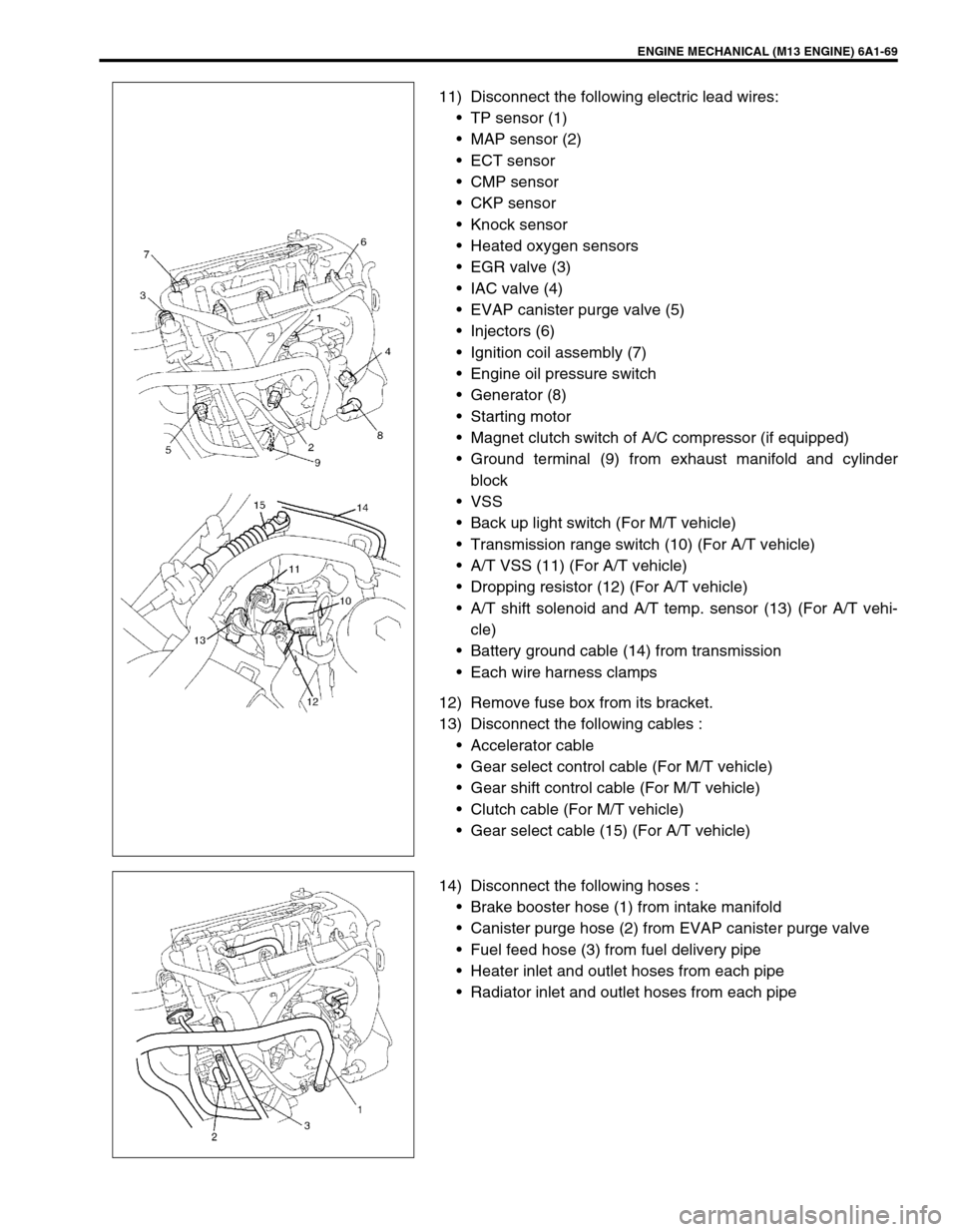
11) Disconnect the following electric lead wires:
TP sensor (1)
MAP sensor (2)
ECT sensor
CMP sensor
CKP sensor
Knock sensor
Heated oxygen sensors
EGR valve (3)
IAC valve (4)
EVAP canister purge valve (5)
Injectors (6)
Ignition coil assembly (7)
Engine oil pressure switch
Generator (8)
Starting motor
Magnet clutch switch of A/C compressor (if equipped)
Ground terminal (9) from exhaust manifold and cylinder
block
VSS
Back up light switch (For M/T vehicle)
Transmission range switch (10) (For A/T vehicle)
A/T VSS (11) (For A/T vehicle)
Dropping resistor (12) (For A/T vehicle)
A/T shift solenoid and A/T temp. sensor (13) (For A/T vehi-
cle)
Battery ground cable (14) from transmission
Each wire harness clamps
12) Remove fuse box from its bracket.
13) Disconnect the following cables :
Accelerator cable
Gear select control cable (For M/T vehicle)
Gear shift control cable (For M/T vehicle)
Clutch cable (For M/T vehicle)
Gear select cable (15) (For A/T vehicle)
14) Disconnect the following hoses :
Brake booster hose (1) from intake manifold
Canister purge hose (2) from EVAP canister purge valve
Fuel feed hose (3) from fuel delivery pipe
Heater inlet and outlet hoses from each pipe
Radiator inlet and outlet hoses from each pipe
Page 626 of 698

ENGINE AND EMISSION CONTROL SYSTEM 6E1-5
AIR INTAKE SYSTEM
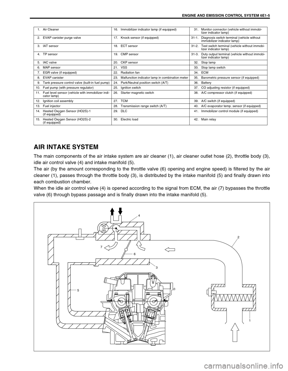
The main components of the air intake system are air cleaner (1), air cleaner outlet hose (2), throttle body (3),
idle air control valve (4) and intake manifold (5).
The air (by the amount corresponding to the throttle valve (6) opening and engine speed) is filtered by the air
cleaner (1), passes through the throttle body (3), is distributed by the intake manifold (5) and finally drawn into
each combustion chamber.
When the idle air control valve (4) is opened according to the signal from ECM, the air (7) bypasses the throttle
valve (6) through bypass passage and is finally drawn into the intake manifold (5).
1. Air Cleaner 16. Immobilizer indicator lamp (if equipped) 31. Monitor connector (vehicle without immobi-
lizer indicator lamp)
2. EVAP canister purge valve 17. Knock sensor (if equipped) 31-1. Diagnosis switch terminal (vehicle without
immobilizer indicator lamp)
3. IAT sensor 18. ECT sensor 31-2. Test switch terminal (vehicle without immobi-
lizer indicator lamp)
4. TP sensor 19. CMP sensor 31-3. Duty output terminal (vehicle without immobi-
lizer indicator lamp)
5. IAC valve 20. CKP sensor 32. Stop lamp
6. MAP sensor 21. VSS 33. Stop lamp switch
7. EGR valve (if equipped) 22. Radiation fan 34. ECM
8. EVAP canister 23. Malfunction indicator lamp in combination meter 35. Barometric pressure sensor (if equipped)
9. Tank pressure control valve (built-in fuel pump) 24. Park/Neutral position switch (A/T) 36. Battery
10. Fuel pump (with pressure regulator) 25. Ignition switch 37. CO adjusting resistor (if equipped)
11. Fuel level sensor (vehicle with immobilizer indi-
cator lamp)26. Starter magnetic switch 38. A/C compressor clutch (if equipped)
12. Ignition coil assembly 27. TCM 39. A/C switch (if equipped)
13. Fuel injector 28. Transmission range switch (A/T) 40. A/C evaporator temp. sensor (if equipped)
14. Heated Oxygen Sensor (HO2S)-1
(if equipped)29. DLC 41. Immobilizer control module (if equipped)
15. Heated Oxygen Sensor (HO2S)-2
(if equipped)30. Electric load 42. Main relay
54
2
1
6
3
7
Page 628 of 698

ENGINE AND EMISSION CONTROL SYSTEM 6E1-7
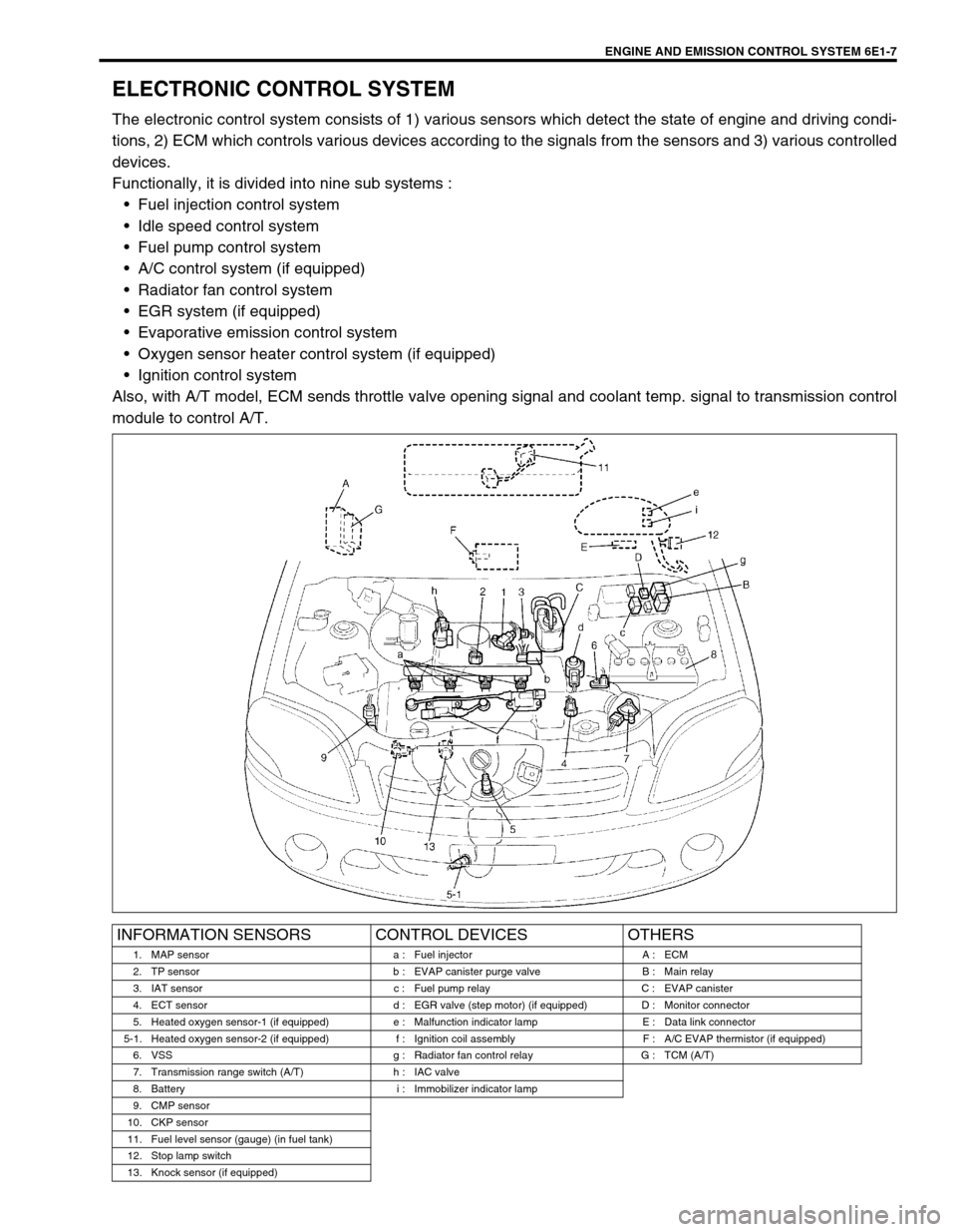
ELECTRONIC CONTROL SYSTEM
The electronic control system consists of 1) various sensors which detect the state of engine and driving condi-
tions, 2) ECM which controls various devices according to the signals from the sensors and 3) various controlled
devices.
Functionally, it is divided into nine sub systems :
Fuel injection control system
Idle speed control system
Fuel pump control system
A/C control system (if equipped)
Radiator fan control system
EGR system (if equipped)
Evaporative emission control system
Oxygen sensor heater control system (if equipped)
Ignition control system
Also, with A/T model, ECM sends throttle valve opening signal and coolant temp. signal to transmission control
module to control A/T.
INFORMATION SENSORS CONTROL DEVICES OTHERS
1. MAP sensor a : Fuel injector A : ECM
2. TP sensor b : EVAP canister purge valve B : Main relay
3. IAT sensor c : Fuel pump relay C : EVAP canister
4. ECT sensor d : EGR valve (step motor) (if equipped) D : Monitor connector
5. Heated oxygen sensor-1 (if equipped) e : Malfunction indicator lamp E : Data link connector
5-1. Heated oxygen sensor-2 (if equipped) f : Ignition coil assembly F : A/C EVAP thermistor (if equipped)
6. VSS g : Radiator fan control relay G : TCM (A/T)
7. Transmission range switch (A/T) h : IAC valve
8. Battery i : Immobilizer indicator lamp
9. CMP sensor
10. CKP sensor
11. Fuel level sensor (gauge) (in fuel tank)
12. Stop lamp switch
13. Knock sensor (if equipped)