Page 49 of 698

0B-20 MAINTENANCE AND LUBRICATION
ENGINE START
Check engine start for readiness.
On automatic transmission vehicles, try to start the engine in each select lever position. The starting motor
should crank only in “P” (Park) or “N” (Neutral).
On manual transmission vehicles, place the shift lever in “Neutral,” depress clutch pedal fully any try to start.
EXHAUST SYSTEM CHECK
Check for leakage, cracks or loose supports.
CLUTCH (FOR MANUAL TRANSMISSION)
Check for the following.
Clutch is completely released when depressing clutch pedal,
No slipping clutch occurs when releasing pedal and accelerating.
Clutch itself is free from any abnormal condition.
GEARSHIFT OR SELECT LEVER (TRANSMISSION)
Check gear shift or select lever for smooth shifting to all positions and for good performance of transmission in
any position.
With automatic transmission equipped vehicle, also check that shift indicator indicates properly according to
which position select lever is shifted to.
With automatic transmission equipped vehicle, make sure that vehicle is at complete stop when shifting select
lever to “P” range position and release all brakes.
BRAKE
Foot Brake
Check the followings:
that brake pedal has proper travel,
that brake works properly,
that it is free from noise,
that vehicle does not pull to one side when brake is applied.
and that brake do not drag.
Parking Brake
Check that lever has proper travel.
Check to ensure that parking brake is fully effective when the vehicle is stopped on the safe slope and brake
lever is pulled all the way.WARNING:
Before performing the following check, be sure to have enough room around the vehicle. Then, firmly
apply both the parking brake and the regular brakes. Do not use the accelerator pedal. If the engine
starts, be ready to turn off the ignition promptly. Take these precautions because the vehicle could
move without warning and possibly cause personal injury or property damage.
WARNING:
With vehicle parked on a fairly steep slope, make sure nothing is in the way downhill to avoid any per-
sonal injury or property damage. Be prepared to apply regular brake quickly even if vehicle should
start to move.
Page 50 of 698

MAINTENANCE AND LUBRICATION 0B-21
STEERING
Check to ensure that steering wheel is free from instability, or abnormally heavy feeling.
Check that the vehicle does not wander or pull to one side.
ENGINE
Check that engine responds readily at all speeds.
Check that engine is free from abnormal noise and abnormal vibration.
BODY, WHEELS AND POWER TRANSMITTING SYSTEM
Check that body, wheels and power transmitting system are free from abnormal noise and abnormal vibration or
any other abnormal condition.
METERS AND GAUGE
Check that speedometer, odometer, fuel meter, temperature gauge, etc. are operating accurately.
LIGHTS
Check that all lights operate properly.
WINDSHIELD DEFROSTER
Periodically check that air comes out from defroster outlet when operating heater or air conditioning.
Set mode control lever to defroster position and fan switch lever to “HI” position for this check.
RECOMMENDED FLUIDS AND LUBRICANTS
Engine oil SE, SF, SG, SH or SJ grade (Refer to “ENGINE OIL AND OIL FILTER”
in this section for engine oil viscosity.)
Engine coolant
(Ethylene glycol base coolant)“Antifreeze/Anticorrosion coolant”
Brake fluid DOT 3
Manual transmission oil Refer to “M/T OIL CHANGE” in Section 7A.
Transfer oil (4WD) Refer to “TRANSFER OIL CHANGE” in Section 7D.
Differential oil (4WD) Refer to “DIFFERENTIAL OIL CHANGE” in Section 7F.
Automatic transmission fluid
An equivalent of DEXRON
®-III
Door hinges Engine oil or water resistance chassis grease
Hood latch assembly Engine oil or water resistance chassis grease
Key lock cylinder Spray lubricant
Page 268 of 698

FRONT DRIVE SHAFT 4A-15
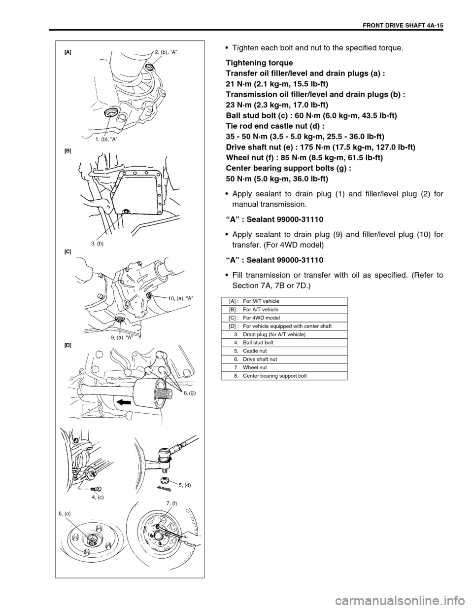
Tighten each bolt and nut to the specified torque.
Tightening torque
Transfer oil filler/level and drain plugs (a) :
21 N·m (2.1 kg-m, 15.5 lb-ft)
Transmission oil filler/level and drain plugs (b) :
23 N·m (2.3 kg-m, 17.0 lb-ft)
Ball stud bolt (c) : 60 N·m (6.0 kg-m, 43.5 lb-ft)
Tie rod end castle nut (d) :
35 - 50 N·m (3.5 - 5.0 kg-m, 25.5 - 36.0 lb-ft)
Drive shaft nut (e) : 175 N·m (17.5 kg-m, 127.0 lb-ft)
Wheel nut (f) : 85 N·m (8.5 kg-m, 61.5 lb-ft)
Center bearing support bolts (g) :
50 N·m (5.0 kg-m, 36.0 lb-ft)
Apply sealant to drain plug (1) and filler/level plug (2) for
manual transmission.
“A” : Sealant 99000-31110
Apply sealant to drain plug (9) and filler/level plug (10) for
transfer. (For 4WD model)
“A” : Sealant 99000-31110
Fill transmission or transfer with oil as specified. (Refer to
Section 7A, 7B or 7D.)
[A] : For M/T vehicle
[B] : For A/T vehicle
[C] : For 4WD model
[D] : For vehicle equipped with center shaft
3. Drain plug (for A/T vehicle)
4. Ball stud bolt
5. Castle nut
6. Drive shaft nut
7. Wheel nut
8. Center bearing support bolt
Page 269 of 698
4A-16 FRONT DRIVE SHAFT
TIGHTENING TORQUE SPECIFICATION
REQUIRED SERVICE MATERIAL
SPECIAL TOOL
Fastening portionTightening torque
Nm kg-m lb-ft
Transfer oil filler/level and drain plugs 21 2.1 15.5
Transmission oil filler/level and drain plugs 23 2.3 17.0
Ball stud bolt 60 6.0 43.5
Tie rod end castle nut 35 - 50 3.5 - 5.0 25.5 - 36.0
Drive shaft nut 175 17.5 127.0
Wheel nut 85 8.5 61.5
Center bearing support bolts 50 5.0 36.0
MaterialRecommended SUZUKI product
(Part Number)Use
Lithium grease SUZUKI SUPER GREASE A
(99000-25010)Oil seal lips
Sealant SUZUKI BOND NO. 1215
(99000-31110)Oil drain and filler plug for manual
transmission or transfer
09913-65210 09900-06107 09900-06108
Tie-rod end remover Snap ring pliers (Open
type)Snap ring pliers (Closing
type)
Page 689 of 698

CHARGING SYSTEM 6H-9
ON-VEHICLE SERVICE
BATTERY
JUMP STARTING IN CASE OF EMERGENCY
WITH AUXILIARY (BOOSTER) BATTERY
Both booster and discharged battery should be treated carefully when using jumper cables. Follow procedure
outlined below, being careful not to cause sparks.
1) Set parking brake and place automatic transmission in PARK (NEUTRAL on manual transmission). Turn off
ignition, turn off lights and all other electrical loads.
2) Check electrolyte level. If it is below low level line, add distilled water.
3) Attach end of one jumper cable to positive terminal of booster battery and the other end of the same cable to
positive terminal of discharged battery. (Use 12-volt battery only to jump start engine).
4) Attach one end of the remaining negative cable to negative terminal of booster battery, and the other end to
a solid engine ground (such as exhaust manifold) at least 45 cm (18 in.) away from battery of vehicle being
started.
5) Start engine of vehicle with booster battery and turn off electrical accessories. Then Start engine of the vehi-
cle with discharged battery.
6) Disconnect jumper cables in the exact reverse order.
WITH CHARGING EQUIPMENT
CAUTION:
If vehicle is manual transmission model and has a catalytic converter, do not push or tow it to start.
Damage to its emission system and/or to other parts may result.
WARNING:
Departure from these conditions or procedure described below could result in:
–Serious personal injury (particularly to eyes) or property damage from such causes as battery
explosion, battery acid, or electrical burns.
–Damage to electronic components of either vehicle.
Remove rings, watches, and other jewelry. Wear approved eye protection.
Be careful so that metal tools or jumper cables do not contact positive battery terminal (or metal in
contact with it) and any other metal on vehicle, because a short circuit could occur.
WARNING:
Do not connect negative cable directly to negative terminal of dead battery.
CAUTION:
When jump starting engine with charging equipment, be sure equipment used is 12-volt and negative
ground. Do not use 24-volt charging equipment. Using such equipment can cause serious damage to
electrical system or electronic parts.