2000 SUZUKI SWIFT low oil pressure
[x] Cancel search: low oil pressurePage 113 of 698
3-4 STEERING, SUSPENSION, WHEELS AND TIRES
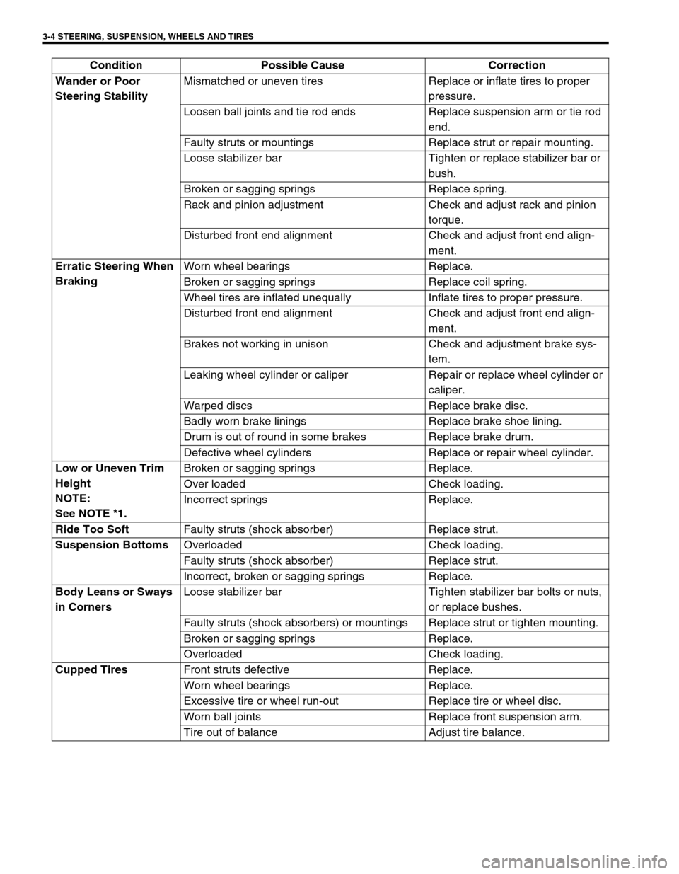
Wander or Poor
Steering StabilityMismatched or uneven tires Replace or inflate tires to proper
pressure.
Loosen ball joints and tie rod ends Replace suspension arm or tie rod
end.
Faulty struts or mountings Replace strut or repair mounting.
Loose stabilizer bar Tighten or replace stabilizer bar or
bush.
Broken or sagging springs Replace spring.
Rack and pinion adjustment Check and adjust rack and pinion
torque.
Disturbed front end alignment Check and adjust front end align-
ment.
Erratic Steering When
BrakingWorn wheel bearings Replace.
Broken or sagging springs Replace coil spring.
Wheel tires are inflated unequally Inflate tires to proper pressure.
Disturbed front end alignment Check and adjust front end align-
ment.
Brakes not working in unison Check and adjustment brake sys-
tem.
Leaking wheel cylinder or caliper Repair or replace wheel cylinder or
caliper.
Warped discs Replace brake disc.
Badly worn brake linings Replace brake shoe lining.
Drum is out of round in some brakes Replace brake drum.
Defective wheel cylinders Replace or repair wheel cylinder.
Low or Uneven Trim
Height
NOTE:
See NOTE *1.Broken or sagging springs Replace.
Over loaded Check loading.
Incorrect springs Replace.
Ride Too Soft
Faulty struts (shock absorber) Replace strut.
Suspension Bottoms
Overloaded Check loading.
Faulty struts (shock absorber) Replace strut.
Incorrect, broken or sagging springs Replace.
Body Leans or Sways
in CornersLoose stabilizer bar Tighten stabilizer bar bolts or nuts,
or replace bushes.
Faulty struts (shock absorbers) or mountings Replace strut or tighten mounting.
Broken or sagging springs Replace.
Overloaded Check loading.
Cupped Tires
Front struts defective Replace.
Worn wheel bearings Replace.
Excessive tire or wheel run-out Replace tire or wheel disc.
Worn ball joints Replace front suspension arm.
Tire out of balance Adjust tire balance. Condition Possible Cause Correction
Page 196 of 698

FRONT SUSPENSION 3D-3
DIAGNOSIS
STABILIZER BAR AND/OR BUSHING CHECK
Bar
Inspect for damage or deformation.
If defective, replace.
Bushing
Inspect for damage, wear or deterioration.
If defective, replace.
STRUT ASSEMBLY CHECK
Inspect strut for oil leakage, damage or deformation.
If strut is found faulty, replace it as an assembly unit,
because it can not be disassembled.
Inspect strut function refer to the following procedures.
1) Check and adjust tire pressures as specified.
2) Bounce vehicle body 3 or 4 times continuously by pushing
front end on the side with strut to be checked.
3) Apply the same amount of force at each push and note strut
resistance both when pushed and rebounding.
4) Also, note how many times vehicle body rebounds before
coming to stop after hands are off. Do the same for strut on
the other side.
5) Compare strut resistance and number of rebalance on the
right with those on the left. And they must be equal in both.
With proper strut, vehicle body should come to stop the
moments hands are off or after only one or two small rebal-
ances.
If conditions of struts are in doubt, compare them with known-
good vehicle or strut.
Inspect bearing for wear, abnormal noise or gripping.
If defective, replace.
Page 217 of 698

3E-4 REAR SUSPENSION
DIAGNOSIS
REAR SHOCK ABSORBER CHECK
Inspect for deformation or damage.
Inspect bushings for wear or damage.
Inspect for evidence of oil leakage.
Replace any defective part.
TRAILING ARM, LATERAL ROD, REAR AXLE,
PEAR AXLE HOUSING AND COIL SPRING
CHECK
Inspect for cracks, deformation or damage.
Inspect bushing for damage, wear or breakage.
Replace any defective part.WARNING:
When handling rear shock absorber (1) in which high-
pressure gas is sealed, make sure to observe the follow-
ing precautions.
Don’t disassemble it.
Don’t put it into the fire.
Don’t store it where it gets hot.
Before disposing it, be sure to drill a hole (approxi-
mately 3 mm (0.12 in.) diameter) (2) in it where shown
by an arrow in figure and let gas and oil out.
Lay it down sideways for this work. The gas itself is
harmless but it may issue out of the hole together with
chips generated by the drill. Therefore, be sure to wear
goggle.
Page 244 of 698

REAR SUSPENSION 3E-31
21) Install wheel and tighten wheel nuts to specified torque.
Tightening torque
Wheel nuts (f) : 85 N·m (8.5 kg-m, 61.5 lb-ft)
22) Upon completion of all jobs, pull parking brake lever with
about 20 kg, (44 lbs) load three to five times so as to obtain
proper drum-to-shoe clearance.
Adjust parking brake cable (for adjustment, see Section 5.)
23) Lower hoist.
24) Tighten right and left trailing arm bolts and nuts (1) and
shock absorber lower bolts (2) to specified torque.
Tighten lateral rod bolt and nut (3) to specified torque.
Tightening torque
Rear trailing arm bolts (a) : 80 N·m (8.0 kg-m, 58.0 lb-ft)
Rear shock absorber lower bolts
(b) : 58 N·m (5.8 kg-m, 42.0 lb-ft)
Lateral rod axle housing side nut
(c) : 50 N·m (5.0 kg-m, 36.5 lb-ft)
Lateral rod body side nut (d) : 65 N·m (6.5 kg-m, 47.0 lb-ft)
25) Check to ensure that brake drum is free from dragging and
proper braking is obtained.
26) Perform brake test (foot brake and parking brake).
(For brake test, see Section 5.)
27) If equipped with LSPV, check and adjust LSPV spring refer-
ring to “LSPV INSPECTION AND ADJUSTMENT” and per-
form “FLUID PRESSURE TEST” in Section 5.
28) Check each installed part for oil leakage.
NOTE:
When tightening these bolts and nuts, be sure that vehi-
cle is off hoist and in non loaded condition.
Page 277 of 698
5-4 BRAKES
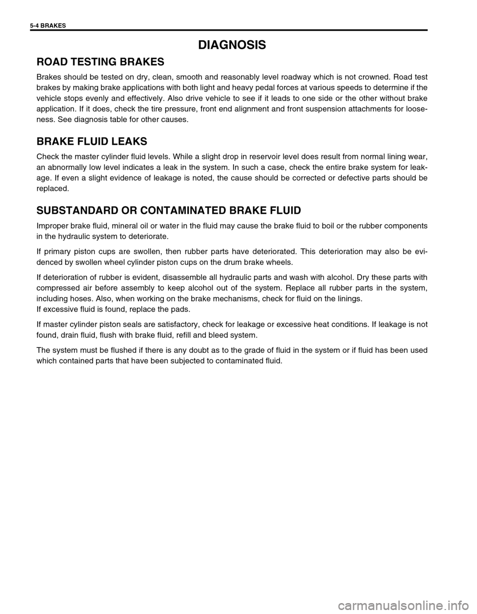
DIAGNOSIS
ROAD TESTING BRAKES
Brakes should be tested on dry, clean, smooth and reasonably level roadway which is not crowned. Road test
brakes by making brake applications with both light and heavy pedal forces at various speeds to determine if the
vehicle stops evenly and effectively. Also drive vehicle to see if it leads to one side or the other without brake
application. If it does, check the tire pressure, front end alignment and front suspension attachments for loose-
ness. See diagnosis table for other causes.
BRAKE FLUID LEAKS
Check the master cylinder fluid levels. While a slight drop in reservoir level does result from normal lining wear,
an abnormally low level indicates a leak in the system. In such a case, check the entire brake system for leak-
age. If even a slight evidence of leakage is noted, the cause should be corrected or defective parts should be
replaced.
SUBSTANDARD OR CONTAMINATED BRAKE FLUID
Improper brake fluid, mineral oil or water in the fluid may cause the brake fluid to boil or the rubber components
in the hydraulic system to deteriorate.
If primary piston cups are swollen, then rubber parts have deteriorated. This deterioration may also be evi-
denced by swollen wheel cylinder piston cups on the drum brake wheels.
If deterioration of rubber is evident, disassemble all hydraulic parts and wash with alcohol. Dry these parts with
compressed air before assembly to keep alcohol out of the system. Replace all rubber parts in the system,
including hoses. Also, when working on the brake mechanisms, check for fluid on the linings.
If excessive fluid is found, replace the pads.
If master cylinder piston seals are satisfactory, check for leakage or excessive heat conditions. If leakage is not
found, drain fluid, flush with brake fluid, refill and bleed system.
The system must be flushed if there is any doubt as to the grade of fluid in the system or if fluid has been used
which contained parts that have been subjected to contaminated fluid.
Page 287 of 698
5-14 BRAKES
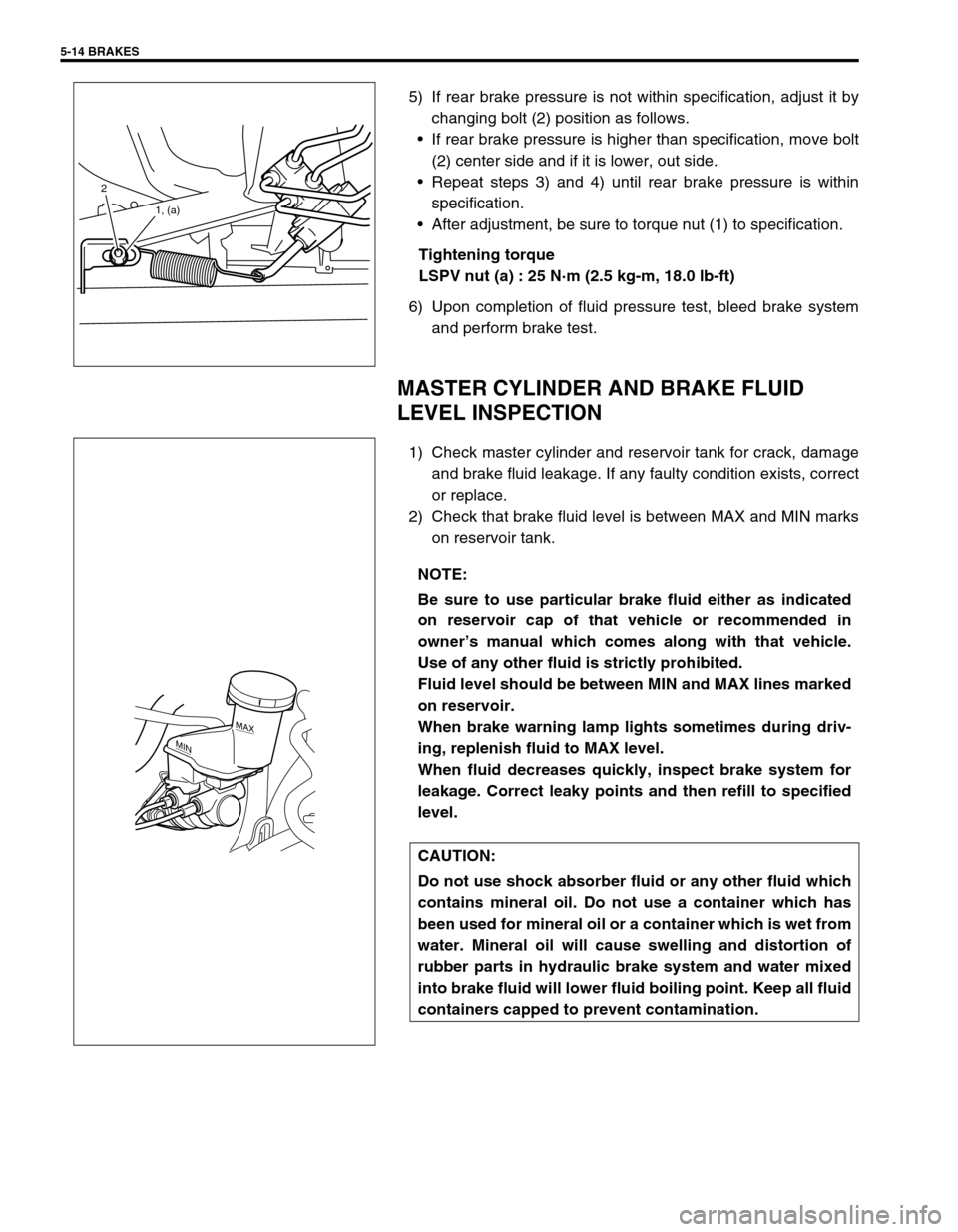
5) If rear brake pressure is not within specification, adjust it by
changing bolt (2) position as follows.
If rear brake pressure is higher than specification, move bolt
(2) center side and if it is lower, out side.
Repeat steps 3) and 4) until rear brake pressure is within
specification.
After adjustment, be sure to torque nut (1) to specification.
Tightening torque
LSPV nut (a) : 25 N·m (2.5 kg-m, 18.0 lb-ft)
6) Upon completion of fluid pressure test, bleed brake system
and perform brake test.
MASTER CYLINDER AND BRAKE FLUID
LEVEL INSPECTION
1) Check master cylinder and reservoir tank for crack, damage
and brake fluid leakage. If any faulty condition exists, correct
or replace.
2) Check that brake fluid level is between MAX and MIN marks
on reservoir tank.
2
1, (a)
NOTE:
Be sure to use particular brake fluid either as indicated
on reservoir cap of that vehicle or recommended in
owner’s manual which comes along with that vehicle.
Use of any other fluid is strictly prohibited.
Fluid level should be between MIN and MAX lines marked
on reservoir.
When brake warning lamp lights sometimes during driv-
ing, replenish fluid to MAX level.
When fluid decreases quickly, inspect brake system for
leakage. Correct leaky points and then refill to specified
level.
CAUTION:
Do not use shock absorber fluid or any other fluid which
contains mineral oil. Do not use a container which has
been used for mineral oil or a container which is wet from
water. Mineral oil will cause swelling and distortion of
rubber parts in hydraulic brake system and water mixed
into brake fluid will lower fluid boiling point. Keep all fluid
containers capped to prevent contamination.
MAX
MIN
Page 311 of 698
5-38 BRAKES
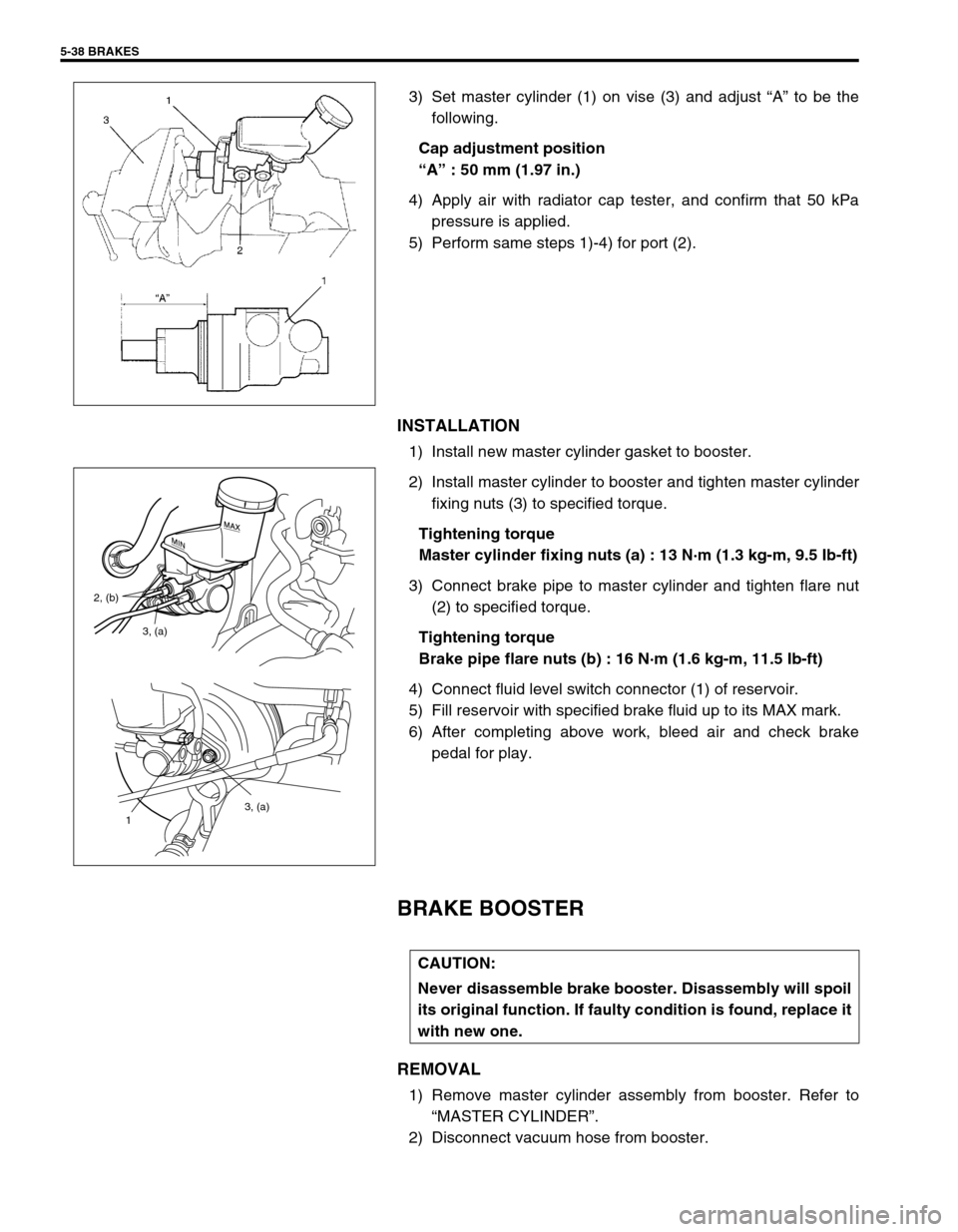
3) Set master cylinder (1) on vise (3) and adjust “A” to be the
following.
Cap adjustment position
“A” : 50 mm (1.97 in.)
4) Apply air with radiator cap tester, and confirm that 50 kPa
pressure is applied.
5) Perform same steps 1)-4) for port (2).
INSTALLATION
1) Install new master cylinder gasket to booster.
2) Install master cylinder to booster and tighten master cylinder
fixing nuts (3) to specified torque.
Tightening torque
Master cylinder fixing nuts (a) : 13 N·m (1.3 kg-m, 9.5 Ib-ft)
3) Connect brake pipe to master cylinder and tighten flare nut
(2) to specified torque.
Tightening torque
Brake pipe flare nuts (b) : 16 N·m (1.6 kg-m, 11.5 Ib-ft)
4) Connect fluid level switch connector (1) of reservoir.
5) Fill reservoir with specified brake fluid up to its MAX mark.
6) After completing above work, bleed air and check brake
pedal for play.
BRAKE BOOSTER
REMOVAL
1) Remove master cylinder assembly from booster. Refer to
“MASTER CYLINDER”.
2) Disconnect vacuum hose from booster.
3, (a)
1
3, (a) 2, (b)
CAUTION:
Never disassemble brake booster. Disassembly will spoil
its original function. If faulty condition is found, replace it
with new one.
Page 322 of 698
BRAKES 5-49
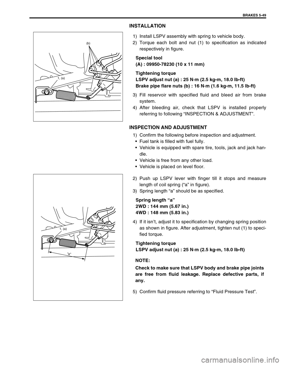
INSTALLATION
1) Install LSPV assembly with spring to vehicle body.
2) Torque each bolt and nut (1) to specification as indicated
respectively in figure.
Special tool
(A) : 09950-78230 (10 x 11 mm)
Tightening torque
LSPV adjust nut (a) : 25 N·m (2.5 kg-m, 18.0 lb-ft)
Brake pipe flare nuts (b) : 16 N·m (1.6 kg-m, 11.5 lb-ft)
3) Fill reservoir with specified fluid and bleed air from brake
system.
4) After bleeding air, check that LSPV is installed properly
referring to following “INSPECTION & ADJUSTMENT”.
INSPECTION AND ADJUSTMENT
1) Confirm the following before inspection and adjustment.
Fuel tank is filled with fuel fully.
Vehicle is equipped with spare tire, tools, jack and jack han-
dle.
Vehicle is free from any other load.
Vehicle is placed on level floor.
2) Push up LSPV lever with finger till it stops and measure
length of coil spring (“a” in figure).
3) Spring length “a” should be as specified.
Spring length “a”
2WD : 144 mm (5.67 in.)
4WD : 148 mm (5.83 in.)
4) If it isn’t, adjust it to specification by changing spring position
as shown in figure. After adjustment, tighten nut (1) to speci-
fied torque.
Tightening torque
LSPV adjust nut (a) : 25 N·m (2.5 kg-m, 18.0 lb-ft)
5) Confirm fluid pressure referring to “Fluid Pressure Test”.
1, (a)
(b)
NOTE:
Check to make sure that LSPV body and brake pipe joints
are free from fluid leakage. Replace defective parts, if
any.
1, (a)
“a”