Page 33 of 698

0B-4 MAINTENANCE AND LUBRICATION
MAINTENANCE RECOMMENDED UNDER SEVERE DRIVING CONDITIONS
If the vehicle is usually used under the conditions corresponding to any severe condition code given below, IT IS
RECOMMENDED that applicable maintenance operation be performed at the particular interval as shown in the
following table.
Severe condition code :
A : Repeated short trips
B : Driving on rough and/or muddy roads
C : Driving on dusty roads
D : Driving in extremely cold weather and/or salted roads
E : Repeated short trips in extremely cold weather
F : Leaded fuel use
G : – – – – –
H : Towing a trailer (if admitted)
Severe
Condition CodeMaintenanceMaintenance
OperationMaintenance Interval
– B C D – – – –Drive beltIEvery 15,000 km
(9,000 miles) or 12 months
REvery 45,000 km
(27,000 miles) or 36 months
A – C D E F – H Engine oil and oil filter REvery 5,000 km
(3,000 miles) or 4 months
– – C – – – – –Air cleaner filter ✱1IEvery 2,500 km
(1,500 miles)
REvery 30,000 km
(18,000 miles) or 24 months
A B C – E F – H Spark plugsNickel spark plug
REvery 10,000 km
(6,000 miles) or 8 months
Iridium spark plug
REvery 30,000 km
(18,000 miles) or 24 months
– B C D – – – H Wheel bearings IEvery 15,000 km
(9,000 miles) or 12 months
– B – D E – – H Drive shafts and propeller shafts (4WD) IEvery 15,000 km
(9,000 miles) or 12 months
– B – – E – – HManual transmission, transfer (4WD) and
differential oil (4WD)REvery 30,000 km
(18,000 miles) or 24 months
– B – – E – – H Automatic transmission fluid REvery 30,000 km
(18,000 miles) or 24 months
NOTE:
“I” : Inspect and correct or replace if necessary
“R” : Replace or change
✱
✱✱ ✱1 : Inspect more frequently if the vehicle is used under dusty conditions.
Page 39 of 698

0B-10 MAINTENANCE AND LUBRICATION
EXHAUST SYSTEM
INSPECTION
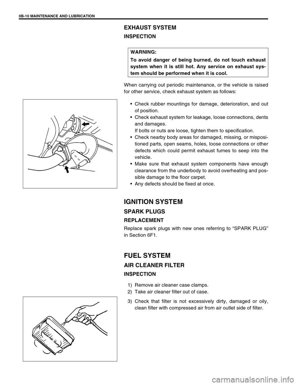
When carrying out periodic maintenance, or the vehicle is raised
for other service, check exhaust system as follows:
Check rubber mountings for damage, deterioration, and out
of position.
Check exhaust system for leakage, loose connections, dents
and damages.
If bolts or nuts are loose, tighten them to specification.
Check nearby body areas for damaged, missing, or misposi-
tioned parts, open seams, holes, loose connections or other
defects which could permit exhaust fumes to seep into the
vehicle.
Make sure that exhaust system components have enough
clearance from the underbody to avoid overheating and pos-
sible damage to the floor carpet.
Any defects should be fixed at once.
IGNITION SYSTEM
SPARK PLUGS
REPLACEMENT
Replace spark plugs with new ones referring to “SPARK PLUG”
in Section 6F1.
FUEL SYSTEM
AIR CLEANER FILTER
INSPECTION
1) Remove air cleaner case clamps.
2) Take air cleaner filter out of case.
3) Check that filter is not excessively dirty, damaged or oily,
clean filter with compressed air from air outlet side of filter. WARNING:
To avoid danger of being burned, do not touch exhaust
system when it is still hot. Any service on exhaust sys-
tem should be performed when it is cool.
Page 40 of 698
MAINTENANCE AND LUBRICATION 0B-11
4) Install air cleaner filter fitting protrusion (1) of filter into
groove (2) of case and clamp upper case securely.
REPLACEMENT
Replace air cleaner filter with new one according to steps 1), 2)
and 4) of inspection procedure.
FUEL LINES AND CONNECTIONS
INSPECTION
Visually inspect fuel lines and connections for evidence of fuel
leakage, hose cracking and damage. Make sure all clamps are
secure.
Repair leaky joints, if any.
Replace hoses that are suspected of being cracked.
FUEL FILTER
REPLACEMENT
Fuel filter (1) is installed in fuel pump assembly (2) in fuel tank.
Replace fuel filter with new one, referring to “FUEL PUMP
ASSEMBLY” in Section 6C for proper procedure.
WARNING:
This work must be performed in a well ventilated area
and away from any open flames (such as gas hot water
heaters).
Page 41 of 698

0B-12 MAINTENANCE AND LUBRICATION
FUEL TANK
INSPECTION
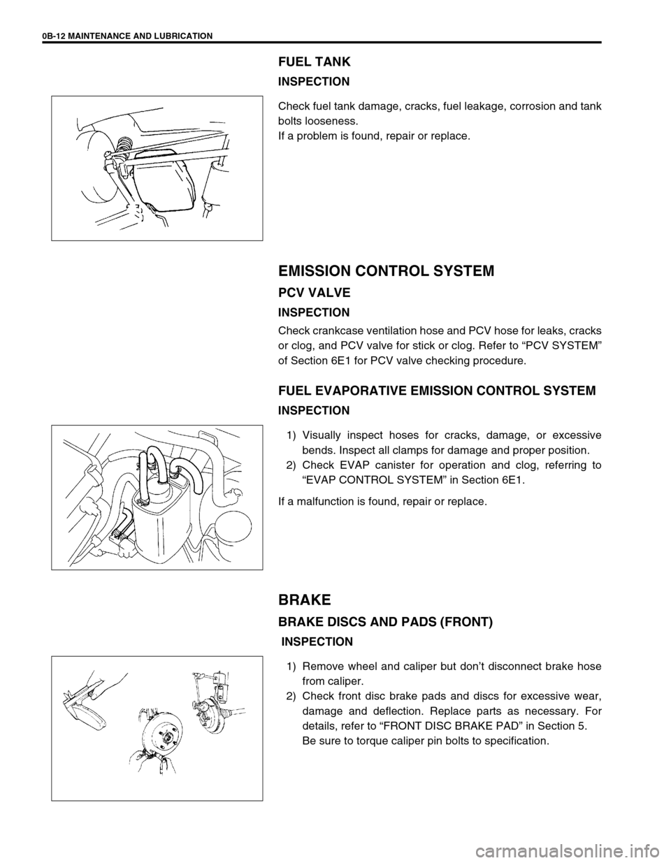
Check fuel tank damage, cracks, fuel leakage, corrosion and tank
bolts looseness.
If a problem is found, repair or replace.
EMISSION CONTROL SYSTEM
PCV VALVE
INSPECTION
Check crankcase ventilation hose and PCV hose for leaks, cracks
or clog, and PCV valve for stick or clog. Refer to “PCV SYSTEM”
of Section 6E1 for PCV valve checking procedure.
FUEL EVAPORATIVE EMISSION CONTROL SYSTEM
INSPECTION
1) Visually inspect hoses for cracks, damage, or excessive
bends. Inspect all clamps for damage and proper position.
2) Check EVAP canister for operation and clog, referring to
“EVAP CONTROL SYSTEM” in Section 6E1.
If a malfunction is found, repair or replace.
BRAKE
BRAKE DISCS AND PADS (FRONT)
INSPECTION
1) Remove wheel and caliper but don’t disconnect brake hose
from caliper.
2) Check front disc brake pads and discs for excessive wear,
damage and deflection. Replace parts as necessary. For
details, refer to “FRONT DISC BRAKE PAD” in Section 5.
Be sure to torque caliper pin bolts to specification.
Page 50 of 698

MAINTENANCE AND LUBRICATION 0B-21
STEERING
Check to ensure that steering wheel is free from instability, or abnormally heavy feeling.
Check that the vehicle does not wander or pull to one side.
ENGINE
Check that engine responds readily at all speeds.
Check that engine is free from abnormal noise and abnormal vibration.
BODY, WHEELS AND POWER TRANSMITTING SYSTEM
Check that body, wheels and power transmitting system are free from abnormal noise and abnormal vibration or
any other abnormal condition.
METERS AND GAUGE
Check that speedometer, odometer, fuel meter, temperature gauge, etc. are operating accurately.
LIGHTS
Check that all lights operate properly.
WINDSHIELD DEFROSTER
Periodically check that air comes out from defroster outlet when operating heater or air conditioning.
Set mode control lever to defroster position and fan switch lever to “HI” position for this check.
RECOMMENDED FLUIDS AND LUBRICANTS
Engine oil SE, SF, SG, SH or SJ grade (Refer to “ENGINE OIL AND OIL FILTER”
in this section for engine oil viscosity.)
Engine coolant
(Ethylene glycol base coolant)“Antifreeze/Anticorrosion coolant”
Brake fluid DOT 3
Manual transmission oil Refer to “M/T OIL CHANGE” in Section 7A.
Transfer oil (4WD) Refer to “TRANSFER OIL CHANGE” in Section 7D.
Differential oil (4WD) Refer to “DIFFERENTIAL OIL CHANGE” in Section 7F.
Automatic transmission fluid
An equivalent of DEXRON
®-III
Door hinges Engine oil or water resistance chassis grease
Hood latch assembly Engine oil or water resistance chassis grease
Key lock cylinder Spray lubricant
Page 251 of 698

3F-6 WHEELS AND TIRES
INFLATION OF TIRES
The pressure recommended for any model is carefully calculated to give a satisfactory ride, stability, steering,
tread wear, tire life and resistance to bruises.
Tire pressure, with tires cold, (after vehicle has set for 3 hours or more, or driven less than one mile) should be
checked monthly or before any extended trip. Set to the specifications on the “Tire Placard” located on the left
door (right door for right-hand side steering vehicle) lock pillar.
It is normal for tire pressure to increase when the tires become hot during driving.
Do not bleed or reduce tire pressure after driving. Bleeding reduces the “Cold Inflation Pressure”.
Higher than recommended pressure can cause :
Hard ride
Tire bruising or carcass damage
Rapid tread wear at center of tire
Unequal pressure on same axle can cause :
Uneven braking
Steering lead
Reduced handling
Swerve on acceleration
Lower than recommended pressure can cause :
Tire squeal on turns
Hard Steering
Rapid and uneven wear on the edges of the tread
Tire rim bruises and rupture
Tire cord breakage
High tire temperature
Reduced handling
High fuel consumption
TIRE ROTATION
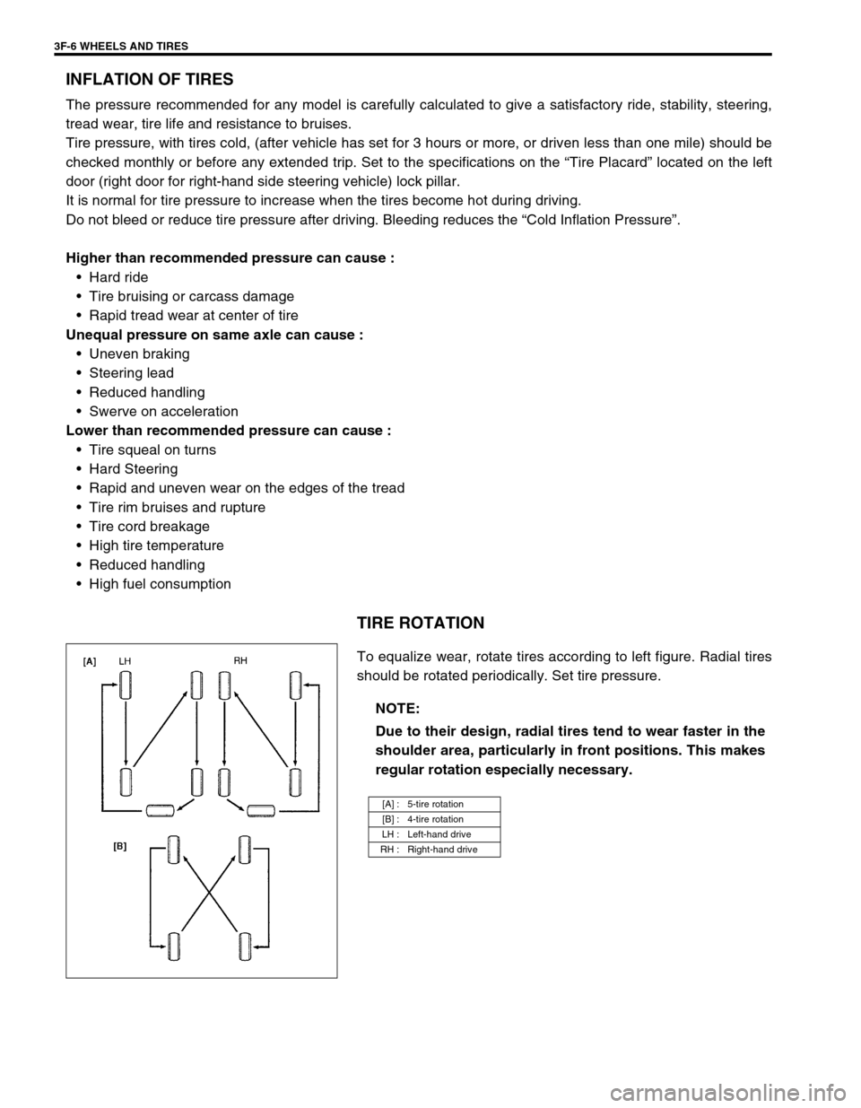
To equalize wear, rotate tires according to left figure. Radial tires
should be rotated periodically. Set tire pressure.
NOTE:
Due to their design, radial tires tend to wear faster in the
shoulder area, particularly in front positions. This makes
regular rotation especially necessary.
[A] : 5-tire rotation
[B] : 4-tire rotation
LH : Left-hand drive
RH : Right-hand drive
Page 285 of 698
5-12 BRAKES
2) Start engine while depressing brake pedal. If pedal travel
increases a little, operation is satisfactory. But no change in
pedal travel indicates malfunction.
CHECK AIR TIGHTNESS UNDER LOAD
1) With engine running, depress brake pedal. Then stop engine
while holding brake pedal depressed.
2) Hold brake pedal depressed for 30 seconds. If pedal height
does not change, condition is good. But it isn’t if pedal rises.
FLUID PRESSURE TEST (IF EQUIPPED WITH
LSPV)
Test procedure for LSPV assembly is as follows.
Before testing, confirm the following.
Fuel tank is filled with fuel fully.
Vehicle is equipped with spare tire, tools, jack and jack han-
dle.
H: Hold
H: Hold
T: 30 seconds
Page 322 of 698

BRAKES 5-49
INSTALLATION
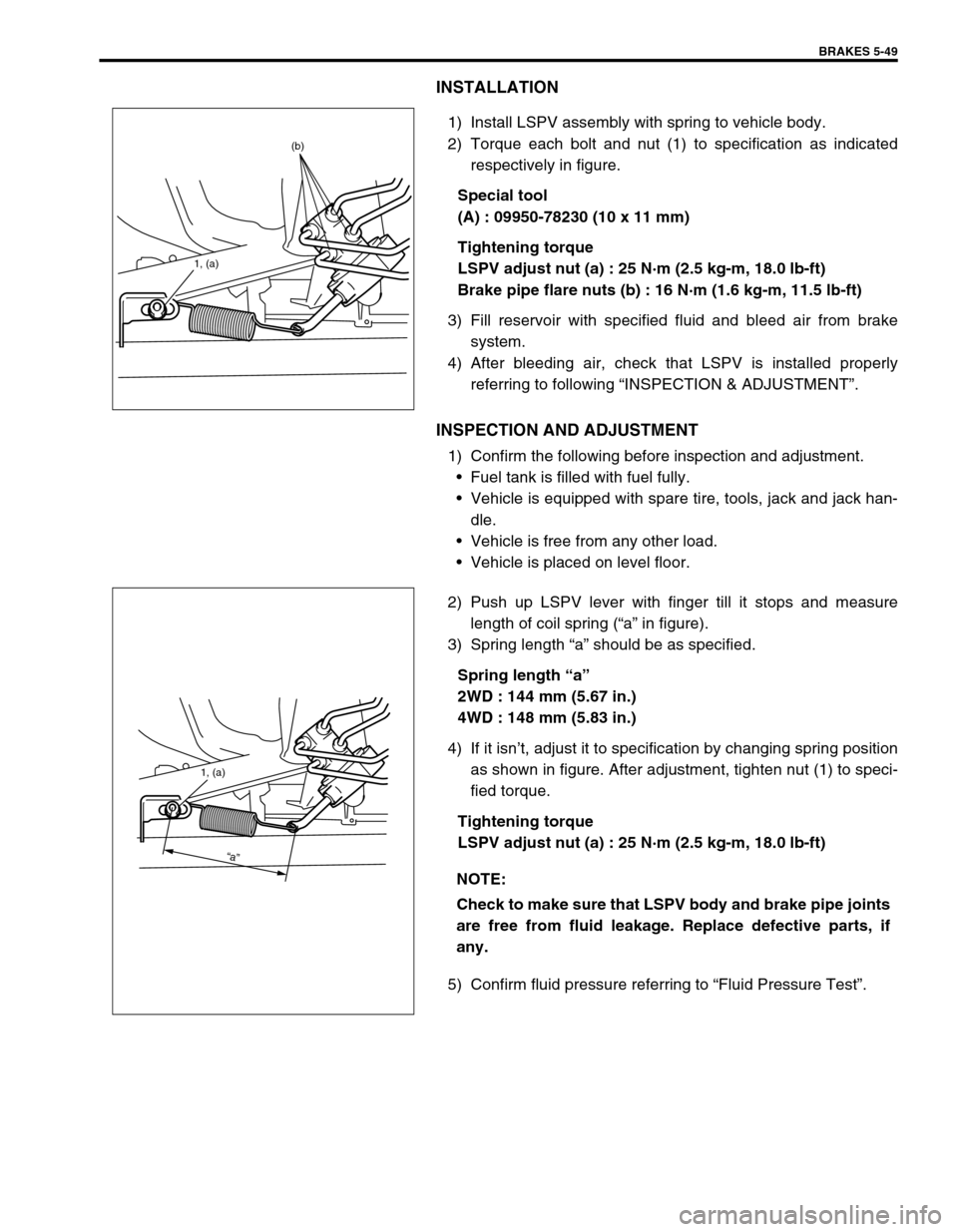
1) Install LSPV assembly with spring to vehicle body.
2) Torque each bolt and nut (1) to specification as indicated
respectively in figure.
Special tool
(A) : 09950-78230 (10 x 11 mm)
Tightening torque
LSPV adjust nut (a) : 25 N·m (2.5 kg-m, 18.0 lb-ft)
Brake pipe flare nuts (b) : 16 N·m (1.6 kg-m, 11.5 lb-ft)
3) Fill reservoir with specified fluid and bleed air from brake
system.
4) After bleeding air, check that LSPV is installed properly
referring to following “INSPECTION & ADJUSTMENT”.
INSPECTION AND ADJUSTMENT
1) Confirm the following before inspection and adjustment.
Fuel tank is filled with fuel fully.
Vehicle is equipped with spare tire, tools, jack and jack han-
dle.
Vehicle is free from any other load.
Vehicle is placed on level floor.
2) Push up LSPV lever with finger till it stops and measure
length of coil spring (“a” in figure).
3) Spring length “a” should be as specified.
Spring length “a”
2WD : 144 mm (5.67 in.)
4WD : 148 mm (5.83 in.)
4) If it isn’t, adjust it to specification by changing spring position
as shown in figure. After adjustment, tighten nut (1) to speci-
fied torque.
Tightening torque
LSPV adjust nut (a) : 25 N·m (2.5 kg-m, 18.0 lb-ft)
5) Confirm fluid pressure referring to “Fluid Pressure Test”.
1, (a)
(b)
NOTE:
Check to make sure that LSPV body and brake pipe joints
are free from fluid leakage. Replace defective parts, if
any.
1, (a)
“a”