2000 SUZUKI SWIFT evaporator
[x] Cancel search: evaporatorPage 81 of 698

1B-16 AIR CONDITIONING (OPTIONAL)
ELECTRICAL DIAGNOSIS
WIRING DIAGRAM
1. Blower fan motor 6. Radiator/condenser cooling fan relay No.2 11. Ignition switch 16. Main fuse box
2. Blower fan motor resistor 7. Radiator/condenser cooling fan relay No.3 12. A/C evaporator temperature sensor 17. Generator
3. Blower fan switch and A/C switch 8. Radiator/condenser cooling fan motor 13. ECT sensor 18. Compressor
4. A/C refrigerant pressure switch 9. Compressor thermal switch 14. Lighting switch
5. Radiator/condenser cooling fan relay No.1 10. Main relay 15. Circuit fuse box
Page 83 of 698

1B-18 AIR CONDITIONING (OPTIONAL)
System Circuit
Terminal arrangement of ECM coupler (Viewed from harness side)
1. Blower fan motor 8. Main relay A. To “HTR” fuse (25 A) in circuit fuse box
2. Blower fan switch 9. Radiator/condenser cooling fan motor relay No.1 B. To main fuse (15 A)
3. A/C switch 10. Radiator/condenser cooling fan motor relay No.2 C. To main fuse (30 A)
4. A/C refrigerant pressure switch 11. Radiator/condenser cooling fan motor relay No.3
5. Compressor 12. Radiator/condenser cooling fan motor
6. A/C evaporator temperature sensor 13. Engine earth
7. ECT sensor 14. ECM
Page 84 of 698

AIR CONDITIONING (OPTIONAL) 1B-19
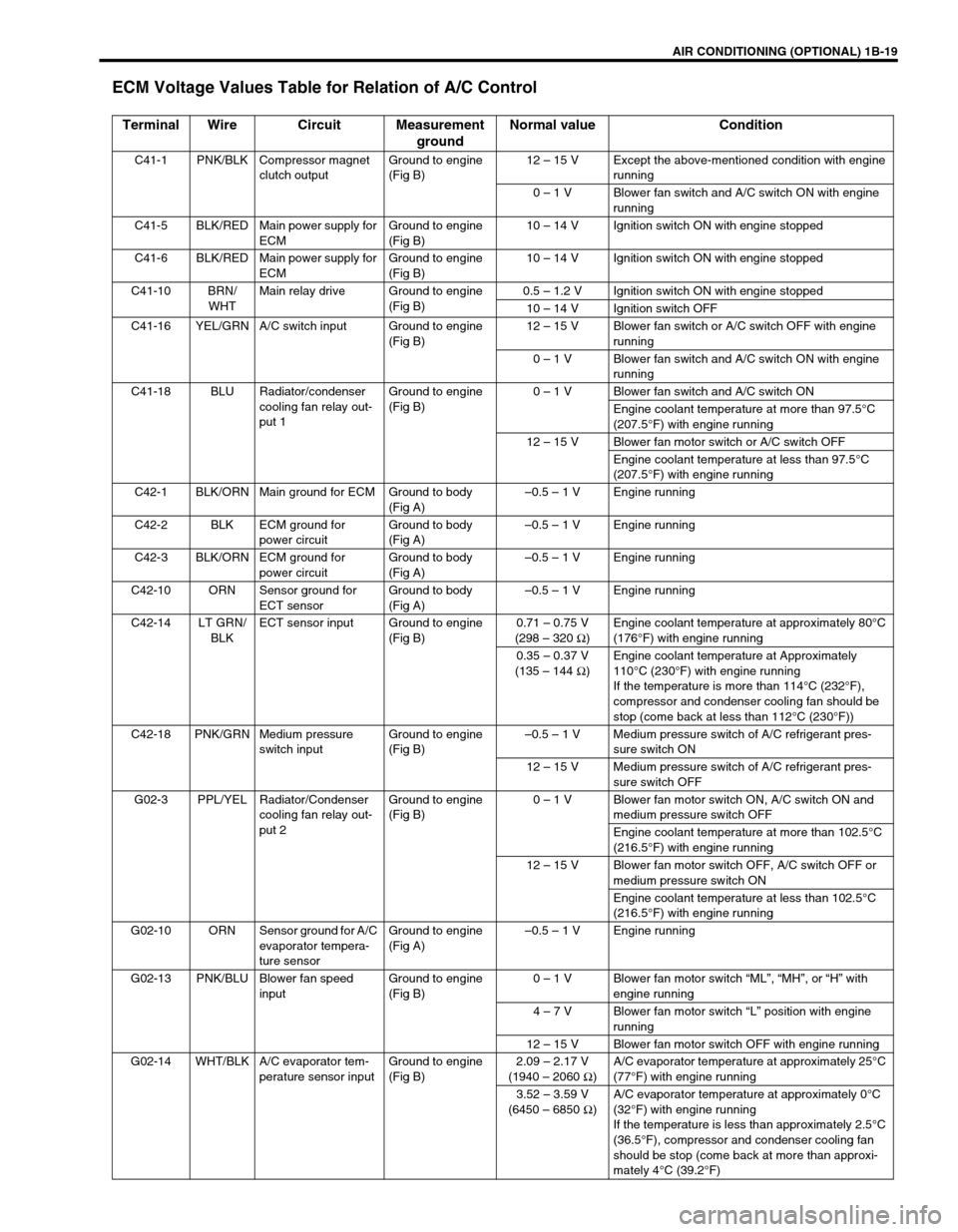
ECM Voltage Values Table for Relation of A/C Control
Terminal Wire Circuit Measurement
groundNormal value Condition
C41-1 PNK/BLK Compressor magnet
clutch outputGround to engine
(Fig B)12 – 15 V Except the above-mentioned condition with engine
running
0 – 1 V Blower fan switch and A/C switch ON with engine
running
C41-5 BLK/RED Main power supply for
ECMGround to engine
(Fig B)10 – 14 V Ignition switch ON with engine stopped
C41-6 BLK/RED Main power supply for
ECMGround to engine
(Fig B)10 – 14 V Ignition switch ON with engine stopped
C41-10 BRN/
WHTMain relay drive Ground to engine
(Fig B)0.5 – 1.2 V Ignition switch ON with engine stopped
10 – 14 V Ignition switch OFF
C41-16 YEL/GRN A/C switch input Ground to engine
(Fig B)12 – 15 V Blower fan switch or A/C switch OFF with engine
running
0 – 1 V Blower fan switch and A/C switch ON with engine
running
C41-18 BLU Radiator/condenser
cooling fan relay out-
put 1Ground to engine
(Fig B)0 – 1 V Blower fan switch and A/C switch ON
Engine coolant temperature at more than 97.5°C
(207.5°F) with engine running
12 – 15 V Blower fan motor switch or A/C switch OFF
Engine coolant temperature at less than 97.5°C
(207.5°F) with engine running
C42-1 BLK/ORN Main ground for ECM Ground to body
(Fig A)–0.5 – 1 V Engine running
C42-2 BLK ECM ground for
power circuitGround to body
(Fig A)–0.5 – 1 V Engine running
C42-3 BLK/ORN ECM ground for
power circuitGround to body
(Fig A)–0.5 – 1 V Engine running
C42-10 ORN Sensor ground for
ECT sensorGround to body
(Fig A)–0.5 – 1 V Engine running
C42-14 LT GRN/
BLKECT sensor input Ground to engine
(Fig B)0.71 – 0.75 V
(298 – 320 Ω
)Engine coolant temperature at approximately 80°C
(176°F) with engine running
0.35 – 0.37 V
(135 – 144 Ω
)Engine coolant temperature at Approximately
110°C (230°F) with engine running
If the temperature is more than 114°C (232°F),
compressor and condenser cooling fan should be
stop (come back at less than 112°C (230°F))
C42-18 PNK/GRN Medium pressure
switch inputGround to engine
(Fig B)–0.5 – 1 V Medium pressure switch of A/C refrigerant pres-
sure switch ON
12 – 15 V Medium pressure switch of A/C refrigerant pres-
sure switch OFF
G02-3 PPL/YEL Radiator/Condenser
cooling fan relay out-
put 2Ground to engine
(Fig B)0 – 1 V Blower fan motor switch ON, A/C switch ON and
medium pressure switch OFF
Engine coolant temperature at more than 102.5°C
(216.5°F) with engine running
12 – 15 V Blower fan motor switch OFF, A/C switch OFF or
medium pressure switch ON
Engine coolant temperature at less than 102.5°C
(216.5°F) with engine running
G02-10 ORN Sensor ground for A/C
evaporator tempera-
ture sensorGround to engine
(Fig A)–0.5 – 1 V Engine running
G02-13 PNK/BLU Blower fan speed
inputGround to engine
(Fig B)0 – 1 V Blower fan motor switch “ML”, “MH”, or “H” with
engine running
4 – 7 V Blower fan motor switch “L” position with engine
running
12 – 15 V Blower fan motor switch OFF with engine running
G02-14 WHT/BLK A/C evaporator tem-
perature sensor inputGround to engine
(Fig B)2.09 – 2.17 V
(1940 – 2060 Ω
)A/C evaporator temperature at approximately 25°C
(77°F) with engine running
3.52 – 3.59 V
(6450 – 6850 Ω
)A/C evaporator temperature at approximately 0°C
(32°F) with engine running
If the temperature is less than approximately 2.5°C
(36.5°F), compressor and condenser cooling fan
should be stop (come back at more than approxi-
mately 4°C (39.2°F)
Page 87 of 698

1B-22 AIR CONDITIONING (OPTIONAL)
WHEN REPLACING COMPRESSOR
Compressor oil is sealed in each new compressor by the amount
required for A/C system. Therefore, when using a new compres-
sor for replacement, drain oil from it by the amount calculated as
follows.
“C” = “A” – “B”
“C” : Amount of oil to be drained
“A” : Amount of oil sealed in a new compressor
“B” : Amount of oil remaining in removed compressor
Oil amount in compressor
: 120 cm
3 (120 cc, 7.32 cu-in)
WHEN REPLACING OTHER PART
Replenish the following amount of oil to compressor.
Amount of compressor oil to be replenished
EVACUATING
EVACUATING PROCEDURE
CAUTION:
Be sure to use HFC-134a (R-134a) compressor oil.
NOTE:
Compressor assembly supplied from factory is filled up
with the following amount of oil.
1. New compressor
2. Removed compressor
3. Excess oil (“A” – “B”)
Replaced part Amount of compressor oil
Evaporator
25 cm
3 (25 cc, 1.53 cu-in)
Condenser
15 cm
3 (15 cc, 0.92 cu-in)
Dryer
20 cm
3 (20 cc, 1.22 cu-in)
Hoses
10 cm
3 (10 cc, 0.61 cu-in) each
Pipes
10 cm
3 (10 cc, 0.61 cu-in) each
CAUTION:
Do not evacuate before recovering refrigerant in system.
NOTE:
Whenever opened (exposed to atmospheric air), air con-
ditioning system must be evacuated by using a vacuum
pump. The A/C system should be attached with a mani-
fold gauge set, and should be evacuated for approxi-
mately 15 minutes.
Page 91 of 698

1B-26 AIR CONDITIONING (OPTIONAL)
REMOVING MANIFOLD GAUGE SET
When A/C system has been charged with a specified amount of refrigerant, remove manifold gauge set as fol-
lows :
1) Close low pressure side valve of manifold gauge set. (The high pressure side valve is closed continuously
during the process of charging.)
2) Close refrigerant container valve.
3) Stop engine.
4) Using shop rag, remove charging hoses from service valves. This operation must be performed rapidly.
5) Put caps on service valves.
LEAK TEST
Whenever a refrigerant leak is suspected in the system or any
service operation has been performed which may result in dis-
turbing lines or connections, it is advisable to test for leaks.
Common sense should be used in performing any refrigerant leak
test, since the need and extent of any such test will, in general,
depend upon the nature of a complaint and the type of a service
performed on the system.
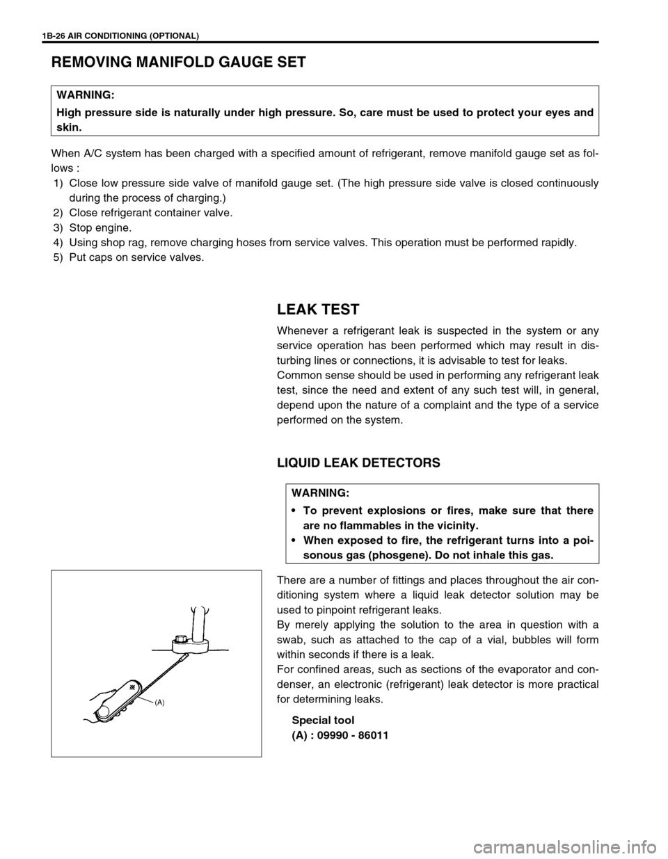
LIQUID LEAK DETECTORS
There are a number of fittings and places throughout the air con-
ditioning system where a liquid leak detector solution may be
used to pinpoint refrigerant leaks.
By merely applying the solution to the area in question with a
swab, such as attached to the cap of a vial, bubbles will form
within seconds if there is a leak.
For confined areas, such as sections of the evaporator and con-
denser, an electronic (refrigerant) leak detector is more practical
for determining leaks.
Special tool
(A) : 09990 - 86011 WARNING:
High pressure side is naturally under high pressure. So, care must be used to protect your eyes and
skin.
WARNING:
To prevent explosions or fires, make sure that there
are no flammables in the vicinity.
When exposed to fire, the refrigerant turns into a poi-
sonous gas (phosgene). Do not inhale this gas.
Page 97 of 698

1B-32 AIR CONDITIONING (OPTIONAL)
COOLING UNIT (EVAPORATOR)
REMOVAL
1) Disconnect negative (–) cable at battery.
2) Recover refrigerant from A/C system by referring to
“RECOVERY” in this section.
3) Remove glove box.
1. A/C evaporator 6. Dash packing 11. O-ring
2. A/C evaporator temperature sensor 7. Packing 12. Door link
3. Expansion valve 8. Fresh air duct case 13. Lower packing
4. Evaporator case
: Apply sealant 99000-31160 to hatched part “A”.9. Clamp Do not reuse.
5. Cooling unit packing 10. Air inlet door
CAUTION:
Be careful not to damage A/C evaporator fins. If A/C
evaporator fin is bent, straighten it by using flat head
screwdriver or pair of pliers.
NOTE:
The amount of removed compressor oil must be mea-
sured for replenishing compressor oil.
Page 98 of 698

AIR CONDITIONING (OPTIONAL) 1B-33
4) Remove fresh air control cable (1) and A/C evaporator tem-
perature sensor coupler.
5) Disconnect suction hose (1) and condenser outlet hose (2)
by removing attaching bolt (3).
6) Remove cooling unit mounting nuts (4) and screws (5).
7) Remove cooling unit (6).
INSPECTION
Check the following.
Clog of A/C evaporator fins.
If any clogs are found, A/C evaporator fins should be
washed with water, and should be dried with compressed
air.
A/C evaporator fins for leakage and breakage.
If any defects are found, repair or replace A/C evaporator.
A/C evaporator fittings for leakage.
If any defects are found, repair or replace A/C evaporator.
INSTALLATION
Reverse removal procedure to install cooling unit noting the fol-
lowing instructions.
If A/C evaporator temperature sensor removed, its should be
reinstalled in original position.
Replenish specified amount of compressor oil to compressor
suction side by referring to “REPLENISHING COMPRES-
SOR OIL” in this section.
Install uniformly the packing (1) to installation hole.
Evacuate and charge refrigerant by referring to “EVACUAT-
ING” and “CHARGING” in this section.
Adjust fresh air control cable, refer to “HEATER LEVER
ASSEMBLY” in Section 1A.
Page 99 of 698

1B-34 AIR CONDITIONING (OPTIONAL)
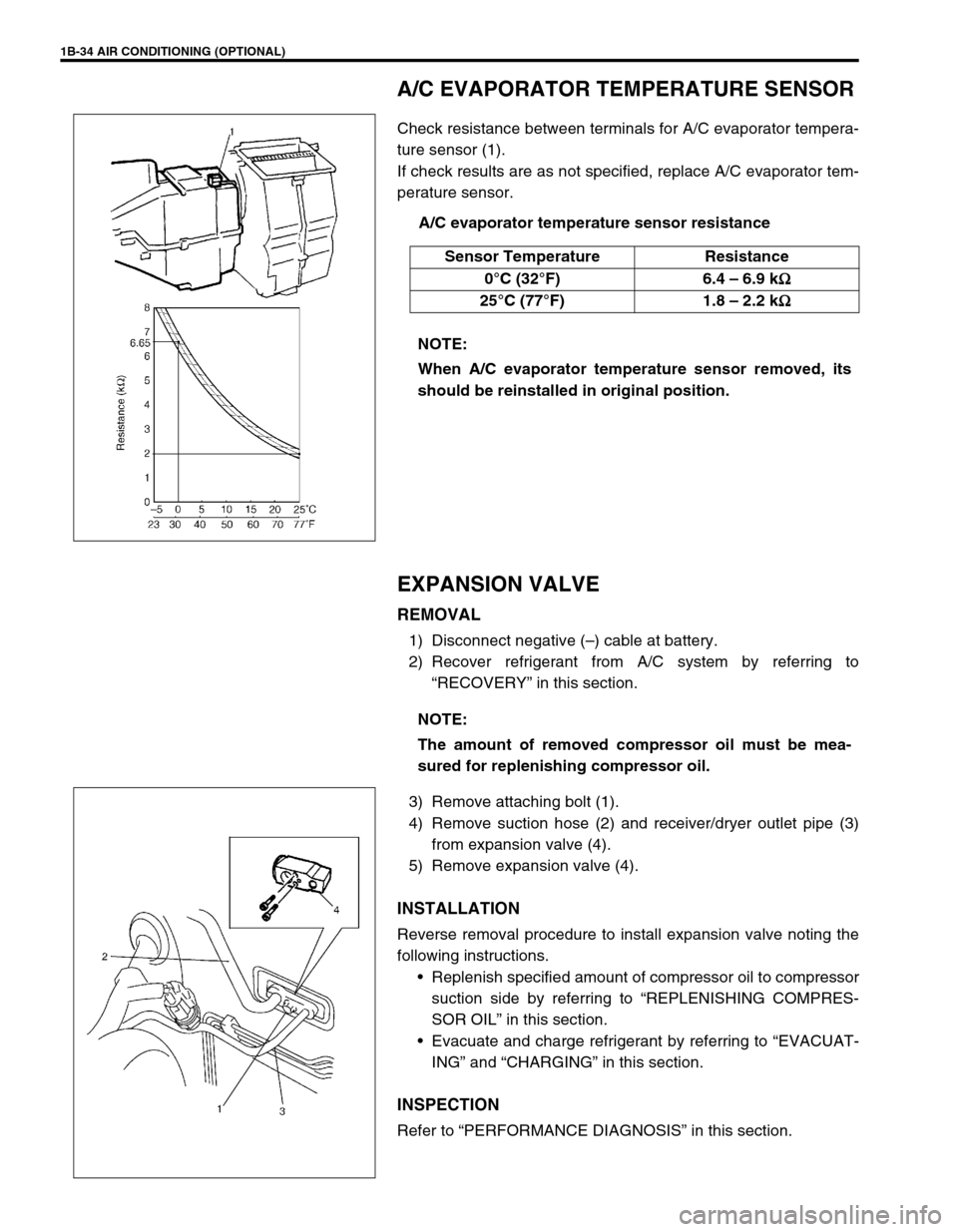
A/C EVAPORATOR TEMPERATURE SENSOR
Check resistance between terminals for A/C evaporator tempera-
ture sensor (1).
If check results are as not specified, replace A/C evaporator tem-
perature sensor.
A/C evaporator temperature sensor resistance
EXPANSION VALVE
REMOVAL
1) Disconnect negative (–) cable at battery.
2) Recover refrigerant from A/C system by referring to
“RECOVERY” in this section.
3) Remove attaching bolt (1).
4) Remove suction hose (2) and receiver/dryer outlet pipe (3)
from expansion valve (4).
5) Remove expansion valve (4).
INSTALLATION
Reverse removal procedure to install expansion valve noting the
following instructions.
Replenish specified amount of compressor oil to compressor
suction side by referring to “REPLENISHING COMPRES-
SOR OIL” in this section.
Evacuate and charge refrigerant by referring to “EVACUAT-
ING” and “CHARGING” in this section.
INSPECTION
Refer to “PERFORMANCE DIAGNOSIS” in this section. Sensor Temperature Resistance
0°C (32°F) 6.4 – 6.9 k
Ω
ΩΩ Ω
25°C (77°F) 1.8 – 2.2 k
Ω
ΩΩ Ω
NOTE:
When A/C evaporator temperature sensor removed, its
should be reinstalled in original position.
NOTE:
The amount of removed compressor oil must be mea-
sured for replenishing compressor oil.