2000 SUZUKI SWIFT RG413 Service Workshop Manual
[x] Cancel search: ACPage 73 of 698

1B-8 AIR CONDITIONING (OPTIONAL)
ABNORMAL NOISE FROM CRANKSHAFT PULLEY
ABNORMAL NOISE FROM TENSION PULLEY
ABNORMAL NOISE FROM A/C EVAPORATOR
ABNORMAL NOISE FROM BLOWER FAN MOTOR
Condition Possible Cause Correction
A large rattling noise
is heard at idle or sud-
den acceleration.Loosen crankshaft pulley bolt Retighten bolt.
Condition Possible Cause Correction
Clattering noise is
heard from pulley.Worn or damaged bearing Replace tension pulley.
Pulley cranks upon
contact.Cracked or loose bracket Replace or retighten bracket.
Condition Possible Cause Correction
Whistling sound is
heard from A/C evapo-
rator.Depending on the combination of the interior/
exterior temperatures, engine rpm and refriger-
ant pressure, the refrigerant flowing out of the
expansion valve may, under certain conditions,
make a whistling soundAt times, slightly decreasing refrig-
erant volume may stop this noise.
Inspect expansion valve and
replace if faulty.
Condition Possible Cause Correction
Blower fan motor
emits a chirping
sound in proportion to
its speed of rotation.Worn or damaged motor brushes or commuta-
torRepair or replace blower fan motor.
Fluttering noise or
large droning noise is
heard from blower fan
motor.Leaves or other debris introduced from fresh air
inlet to blower fan motorRemove debris and make sure that
the screen at fresh air inlet is intact.
Page 74 of 698

AIR CONDITIONING (OPTIONAL) 1B-9
QUICKLY CHECKING OF REFRIGERANT
CHARGE
The following procedure can be used for quickly checking
whether the A/C system has a proper charge of refrigerant or not.
Run engine at fast idle, and operate A/C at its maximum cooling
capacity for a few minutes.
Then, look at the sight glass (1) on condenser outlet pipe (2) and
compare what is observed with the symptoms listed in below.
CHECKING REFRIGERANT CHARGE
[A] : LH model 3. Bubbles
[B] : RH model 4. A/C refrigerant pressure switch
Item
No.Symptom Charge of refrigerant condi-
tionCorrection
1 Bubbles observed in sight glass Insufficient charge of refrigerant
in systemCheck system for leaks with a
leak tester.
2 No bubbles observed in sight glass No or insufficient charge of
refrigerant in systemRefer to the items 3 and 4.
3 No temperature difference between
compressor inlet and outletEmpty or nearly empty system Evacuate and charge system
and then check it for leaks with
a leak tester.
4 Noticeable temperature difference
between compressor inlet and out-
letProper or too much charge of
refrigerant in systemRefer to the items 5 and 6.
5 When A/C is turned OFF, refriger-
ant in sight glass clears immedi-
ately and remains clearToo much charge of refrigerant
in systemRecharge with specified amount
of refrigerant.
6 When A/C is turned OFF, refriger-
ant in sight glass once produces
bubbles and then clearsProper charge of refrigerant in
systemNo correction needed because
charge of refrigerant is normal.
NOTE:
For specified amount of refrigerant, refer to “OPERATION PROCEDURE FOR A/C WITH REFRIGER-
ANT” in this section.
Page 75 of 698

1B-10 AIR CONDITIONING (OPTIONAL)
PERFORMANCE DIAGNOSIS
1) Confirm that vehicle and environmental conditions are as fol-
lows.
Vehicle is not exposed to direct sun.
Ambient temperature is within 15 – 35°C (59 – 95°F).
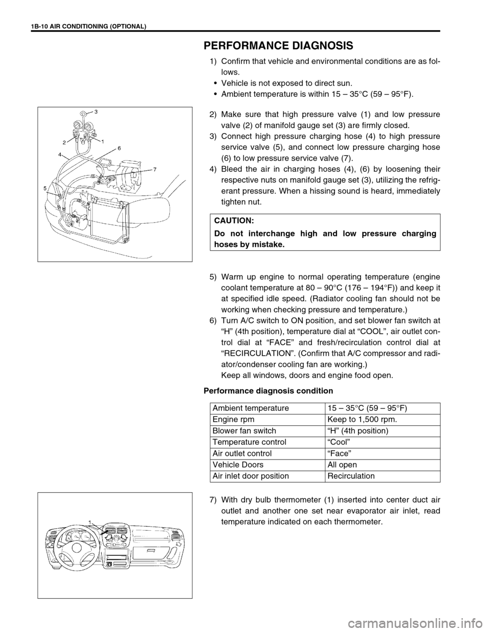
2) Make sure that high pressure valve (1) and low pressure
valve (2) of manifold gauge set (3) are firmly closed.
3) Connect high pressure charging hose (4) to high pressure
service valve (5), and connect low pressure charging hose
(6) to low pressure service valve (7).
4) Bleed the air in charging hoses (4), (6) by loosening their
respective nuts on manifold gauge set (3), utilizing the refrig-
erant pressure. When a hissing sound is heard, immediately
tighten nut.
5) Warm up engine to normal operating temperature (engine
coolant temperature at 80 – 90°C (176 – 194°F)) and keep it
at specified idle speed. (Radiator cooling fan should not be
working when checking pressure and temperature.)
6) Turn A/C switch to ON position, and set blower fan switch at
“H” (4th position), temperature dial at “COOL”, air outlet con-
trol dial at “FACE” and fresh/recirculation control dial at
“RECIRCULATION”. (Confirm that A/C compressor and radi-
ator/condenser cooling fan are working.)
Keep all windows, doors and engine food open.
Performance diagnosis condition
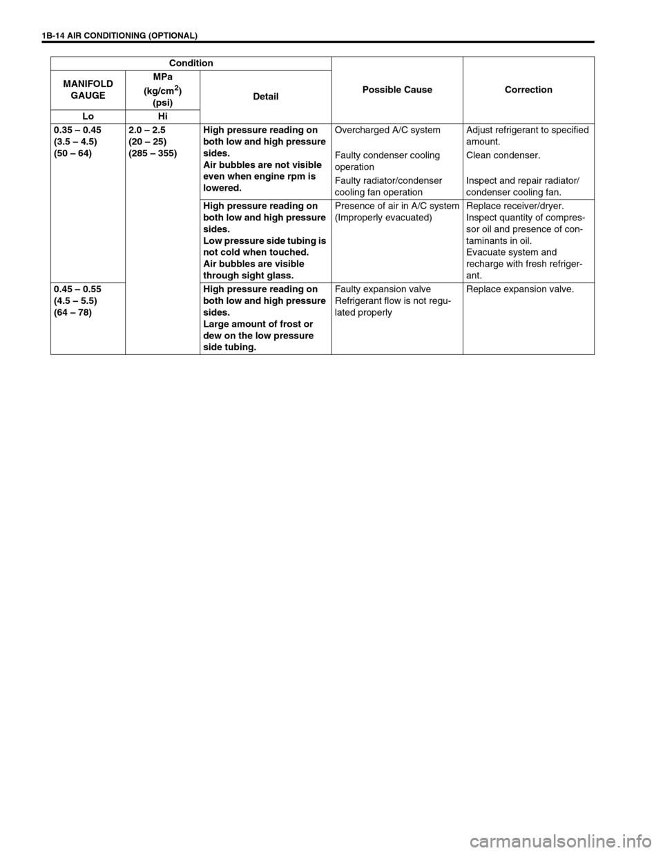
7) With dry bulb thermometer (1) inserted into center duct air
outlet and another one set near evaporator air inlet, read
temperature indicated on each thermometer. CAUTION:
Do not interchange high and low pressure charging
hoses by mistake.
Ambient temperature 15 – 35°C (59 – 95°F)
Engine rpm Keep to 1,500 rpm.
Blower fan switch“H” (4th position)
Temperature control“Cool”
Air outlet control“Face”
Vehicle Doors All open
Air inlet door position Recirculation
Page 76 of 698

AIR CONDITIONING (OPTIONAL) 1B-11
8) Check for each pressure of low side and high side if it is
within shaded range of graph.
If each gauge reading is out of specified pressure, correct
defective part referring to “PERFORMANCE DIAGNOSIS
TABLE”.
Low side and high side pressure example :
9) Check inlet port temperature-to-outlet port temperature rela-
tionship using graph.
For example, if evaporator inlet port temperature is 25°C
(75°F) and center duct air outlet temperature is 8°C (46°F),
their crossing point is within acceptable range as shown in
graph.
If crossing point is out of acceptable range, diagnose trouble
referring to “PERFORMANCE DIAGNOSIS TABLE”. NOTE:
Pressure registered on gauge varies with ambient tem-
perature. Therefore, use the graphs when determining if
pressures are normal or not.
Gauges should read as follows when ambient tempera-
ture is 30°C (86°F).
Pressure
on high pressure gauge1400 – 1750 kPa
14.0 – 17.5 kg/cm
2
199.1 – 248.9 psi
Pressure
on low pressure gauge230 – 350 kPa
2.3 – 3.5 kg/cm
2
32.7 – 49.8 psi
Page 77 of 698

1B-12 AIR CONDITIONING (OPTIONAL)
PERFORMANCE DIAGNOSIS TABLE
HIGH PRESSURE GAUGE
LOW PRESSURE GAUGE
THERMOMETER AT CENTER DUCT
NOTE:
If ambient temperature is approximately 30°C (86°F), it is possible to diagnose A/C system in detail
referring to “DETAIL DIAGNOSIS TABLE (AMBIENT TEMPERATURE AT 30 °C (86°F))” under “PER-
FORMANCE DIAGNOSIS” in this section.
Condition Possible Cause Correction
Pressure high
(“A” area of high side
graph)Refrigerant overcharged Recharge.
Expansion valve frozen or clogged Check expansion valve.
Clogged refrigerant passage of high side Clean or replace.
Radiator/condenser cooling fan malfunction (Insufficient
cooling of condenser)Check radiator/condenser cooling fan.
Dirty or bent condenser fins (Insufficient cooling of con-
denser)Clean or repair.
Compressor malfunction (Insufficient oil etc.) Check compressor.
Engine overheat Check engine cooling system referring to
Section 6B.
Pressure low
(“B” area of high side
graph)Insufficient refrigerant (Insufficient charge or leakage) Check for leakage, repair if necessary
and recharge.
Expansion valve malfunction (valve opens too wide) Check expansion valve.
Compressor malfunction (Insufficient compression) Check compressor.
Condition Possible Cause Correction
Pressure high
(“C” area of low side
graph)Expansion valve malfunction (valve opens too wide) Check expansion valve.
Compressor malfunction (Insufficient compression) Check compressor.
Pressure low
(“D” area of low side
graph)Insufficient refrigerant (Insufficient charge or leakage) Check for leakage, repair if necessary
and recharge.
Expansion valve malfunction (valve opens too narrow) Check expansion valve.
Clogged refrigerant passage (crashed pipe) Repair or replace.
Condition Possible Cause Correction
Outlet air temperature at
center duct is high
(Crossing point is in area
“E”)Insufficient or excessive charge of refrigerant Check refrigerant pressure.
Dirty or bent A/C evaporator fins Clean or repair.
Air leakage from cooling (heater) unit or air duct Repair or replace.
Malfunctioning, switch over function of door in cooling
(heater) unitRepair or replace.
Compressor malfunction Check compressor.
Outlet air temperature at
center duct is low
(Crossing point is in area
“F”)Insufficient air volume from center duct (Heater blower
malfunction)Check blower motor and fan.
Compressor malfunction Check compressor.
Page 78 of 698

AIR CONDITIONING (OPTIONAL) 1B-13
DETAIL DIAGNOSIS TABLE (AMBIENT TEMPERATURE AT 30°C (86°F))
Condition
Possible Cause Correction MANIFOLD
GAUGEMPa
(kg/cm
2)
(psi)Detail
Lo Hi
0.23 – 0.35
(2.3 – 3.5)
(33 – 50)1.4 – 1.75
(14 – 17.5)
(200 – 249)Normal condition––
Negative
pressure0.5 – 0.6
(5 – 6)
(71.2 – 85.3)The low pressure side
reads a negative pressure,
and the high pressure side
reads an extremely low
pressure.
Presence of frost around
tubing to and from receiver/
dryer and expansion valve.Dust particles or water drop-
lets are either stuck or frozen
inside expansion valve, pre-
venting the refrigerant from
flowingClean expansion valve.
Replace it if it cannot be
cleaned.
Replace receiver/dryer.
Evacuate the A/C system and
recharge with fresh refriger-
ant.
Normal :
0.23 – 0.35
(2.3 – 3.5)
(33 – 50)
↑ ↓
↑ ↓↑ ↓ ↑ ↓
Abnormal :
Negative
pressureNormal :
1.4 – 1.75
(14 – 17.5)
(200 – 249)
↑ ↓
↑ ↓↑ ↓ ↑ ↓
Abnormal :
0.7 – 1.0
(7 – 10)
(100 – 142)During A/C operation, the
low pressure side some-
times indicates negative
pressure, and sometimes
normal pressure. Also high
pressure side reading fluc-
tuates between the abnor-
mal and normal pressure.Expansion valve is frozen due
to moisture in the system, and
temporarily shuts off the
refrigeration cycleReplace expansion valve.
Replace receiver/dryer.
Evacuate A/C system and
recharge with fresh refriger-
ant.
0.05 – 0.15
(0.5 – 1.5)
(4.2 – 21.3)0.7 – 1.0
(7 – 10)
(100 – 142)Both low and high pressure
sides indicate low readings.
Continuous air bubbles are
visible through sight glass.
Output air is slightly cold.Insufficient refrigerant in sys-
tem
(Refrigerant leaking)Using leak detector, check for
leaks and repair as neces-
sary.
Recharge refrigerant to a
specified amount.
If the pressure reading is
almost 0 when the manifold
gauges are attached, check
for any leaks, repair them,
and evacuate the system.
0.4 – 0.6
(4 – 6)
(56.9 – 85.3)Pressure on low pressure
side is high.
Pressure on high pressure
side is low.
Both pressure becoming
equal right after A/C is
turned OFF.Internal leak in compressor Inspect compressor and
repair or replace as neces-
sary.
Page 79 of 698

1B-14 AIR CONDITIONING (OPTIONAL)
0.35 – 0.45
(3.5 – 4.5)
(50 – 64)2.0 – 2.5
(20 – 25)
(285 – 355)High pressure reading on
both low and high pressure
sides.
Air bubbles are not visible
even when engine rpm is
lowered.Overcharged A/C system Adjust refrigerant to specified
amount.
Faulty condenser cooling
operationClean condenser.
Faulty radiator/condenser
cooling fan operationInspect and repair radiator/
condenser cooling fan.
High pressure reading on
both low and high pressure
sides.
Low pressure side tubing is
not cold when touched.
Air bubbles are visible
through sight glass.Presence of air in A/C system
(Improperly evacuated)Replace receiver/dryer.
Inspect quantity of compres-
sor oil and presence of con-
taminants in oil.
Evacuate system and
recharge with fresh refriger-
ant.
0.45 – 0.55
(4.5 – 5.5)
(64 – 78)High pressure reading on
both low and high pressure
sides.
Large amount of frost or
dew on the low pressure
side tubing.Faulty expansion valve
Refrigerant flow is not regu-
lated properlyReplace expansion valve. Condition
Possible Cause Correction MANIFOLD
GAUGEMPa
(kg/cm
2)
(psi)Detail
Lo Hi
Page 80 of 698

AIR CONDITIONING (OPTIONAL) 1B-15
COMPRESSOR DRIVE BELT
INSPECTION
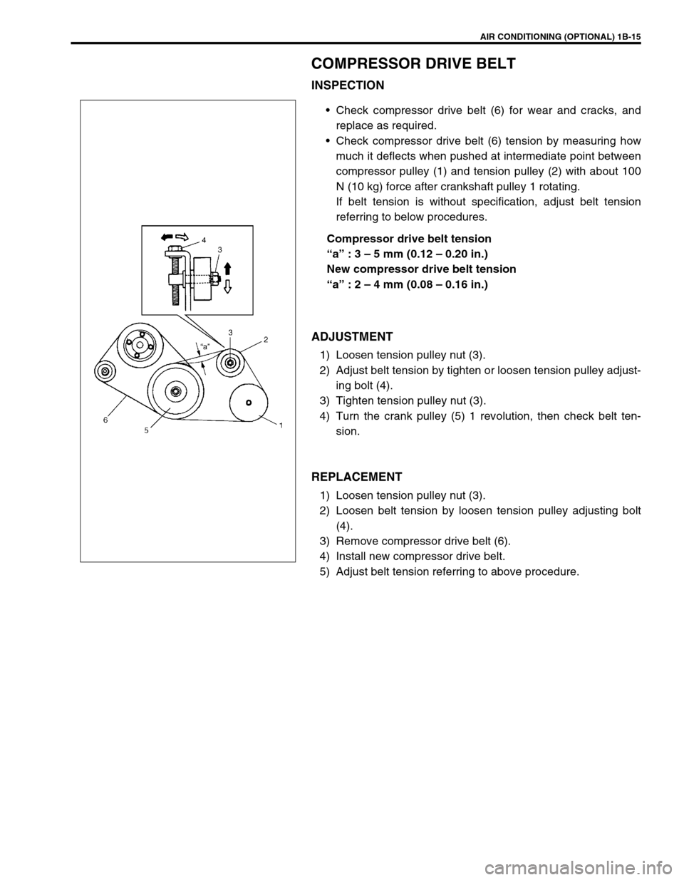
Check compressor drive belt (6) for wear and cracks, and
replace as required.
Check compressor drive belt (6) tension by measuring how
much it deflects when pushed at intermediate point between
compressor pulley (1) and tension pulley (2) with about 100
N (10 kg) force after crankshaft pulley 1 rotating.
If belt tension is without specification, adjust belt tension
referring to below procedures.
Compressor drive belt tension
“a” : 3 – 5 mm (0.12 – 0.20 in.)
New compressor drive belt tension
“a” : 2 – 4 mm (0.08 – 0.16 in.)
ADJUSTMENT
1) Loosen tension pulley nut (3).
2) Adjust belt tension by tighten or loosen tension pulley adjust-
ing bolt (4).
3) Tighten tension pulley nut (3).
4) Turn the crank pulley (5) 1 revolution, then check belt ten-
sion.
REPLACEMENT
1) Loosen tension pulley nut (3).
2) Loosen belt tension by loosen tension pulley adjusting bolt
(4).
3) Remove compressor drive belt (6).
4) Install new compressor drive belt.
5) Adjust belt tension referring to above procedure.