2000 NISSAN PATROL transmission fluid
[x] Cancel search: transmission fluidPage 130 of 1033
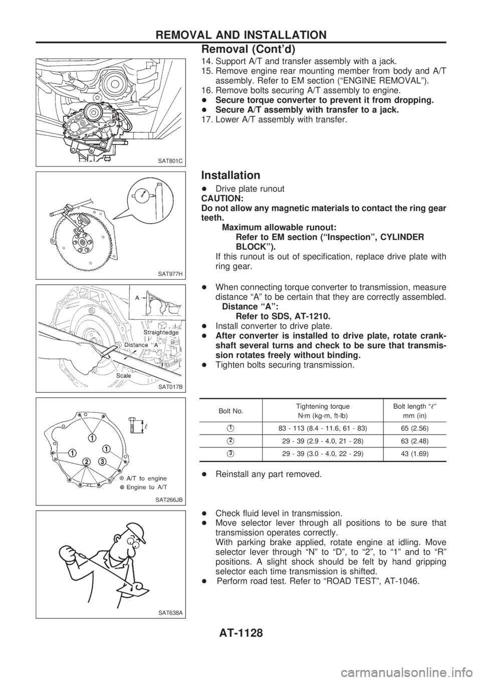
14. Support A/T and transfer assembly with a jack.
15. Remove engine rear mounting member from body and A/T
assembly. Refer to EM section (ªENGINE REMOVALº).
16. Remove bolts securing A/T assembly to engine.
+Secure torque converter to prevent it from dropping.
+Secure A/T assembly with transfer to a jack.
17. Lower A/T assembly with transfer.
Installation
+Drive plate runout
CAUTION:
Do not allow any magnetic materials to contact the ring gear
teeth.
Maximum allowable runout:
Refer to EM section (ªInspectionº, CYLINDER
BLOCKº).
If this runout is out of specification, replace drive plate with
ring gear.
+When connecting torque converter to transmission, measure
distance ªAº to be certain that they are correctly assembled.
Distance ªAº:
Refer to SDS, AT-1210.
+Install converter to drive plate.
+After converter is installed to drive plate, rotate crank-
shaft several turns and check to be sure that transmis-
sion rotates freely without binding.
+Tighten bolts securing transmission.
Bolt No.Tightening torque
Nzm (kg-m, ft-lb)Bolt length ª!º
mm (in)
V183 - 113 (8.4 - 11.6, 61 - 83) 65 (2.56)
V229 - 39 (2.9 - 4.0, 21 - 28) 63 (2.48)
V329 - 39 (3.0 - 4.0, 22 - 29) 43 (1.69)
+Reinstall any part removed.
+Check fluid level in transmission.
+Move selector lever through all positions to be sure that
transmission operates correctly.
With parking brake applied, rotate engine at idling. Move
selector lever through ªNº to ªDº, to ª2º, to ª1º and to ªRº
positions. A slight shock should be felt by hand gripping
selector each time transmission is shifted.
+Perform road test. Refer to ªROAD TESTº, AT-1046.
SAT801C
SAT977H
SAT017B
SAT266JB
SAT638A
REMOVAL AND INSTALLATION
Removal (Cont'd)
AT-1128
Page 136 of 1033
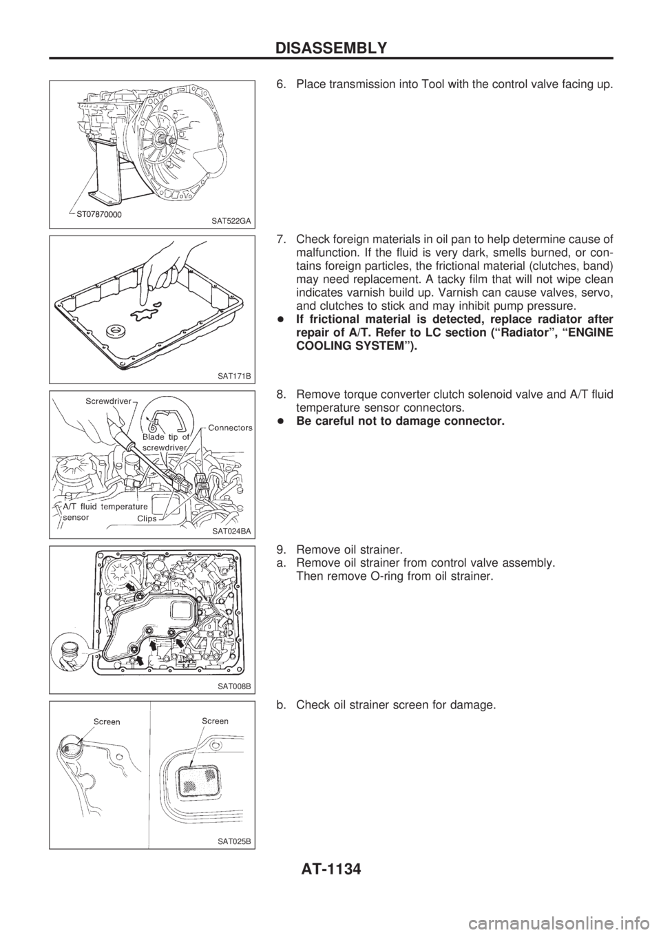
6. Place transmission into Tool with the control valve facing up.
7. Check foreign materials in oil pan to help determine cause of
malfunction. If the fluid is very dark, smells burned, or con-
tains foreign particles, the frictional material (clutches, band)
may need replacement. A tacky film that will not wipe clean
indicates varnish build up. Varnish can cause valves, servo,
and clutches to stick and may inhibit pump pressure.
+If frictional material is detected, replace radiator after
repair of A/T. Refer to LC section (ªRadiatorº, ªENGINE
COOLING SYSTEMº).
8. Remove torque converter clutch solenoid valve and A/T fluid
temperature sensor connectors.
+Be careful not to damage connector.
9. Remove oil strainer.
a. Remove oil strainer from control valve assembly.
Then remove O-ring from oil strainer.
b. Check oil strainer screen for damage.
SAT522GA
SAT171B
SAT024BA
SAT008B
SAT025B
DISASSEMBLY
AT-1134
Page 204 of 1033
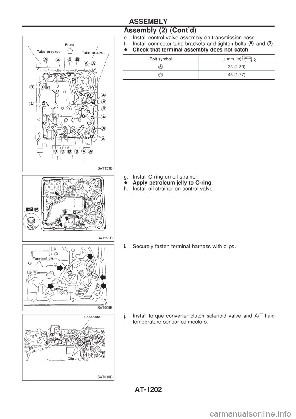
e. Install control valve assembly on transmission case.
f. Install connector tube brackets and tighten bolts
VAandVB.
+Check that terminal assembly does not catch.
Bolt symbol!mm (in)
VA33 (1.30)
VB45 (1.77)
g. Install O-ring on oil strainer.
+Apply petroleum jelly to O-ring.
h. Install oil strainer on control valve.
i. Securely fasten terminal harness with clips.
j. Install torque converter clutch solenoid valve and A/T fluid
temperature sensor connectors.
SAT353B
SAT221B
SAT009B
SAT010B
ASSEMBLY
Assembly (2) (Cont'd)
AT-1202
Page 205 of 1033
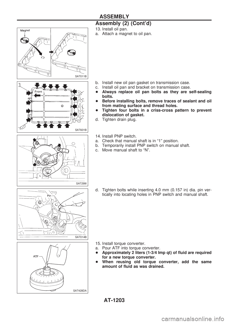
13. Install oil pan.
a. Attach a magnet to oil pan.
b. Install new oil pan gasket on transmission case.
c. Install oil pan and bracket on transmission case.
+Always replace oil pan bolts as they are self-sealing
bolts.
+Before installing bolts, remove traces of sealant and oil
from mating surface and thread holes.
+Tighten four bolts in a criss-cross pattern to prevent
dislocation of gasket.
d. Tighten drain plug.
14. Install PNP switch.
a. Check that manual shaft is in ª1º position.
b. Temporarily install PNP switch on manual shaft.
c. Move manual shaft to ªNº.
d. Tighten bolts while inserting 4.0 mm (0.157 in) dia. pin ver-
tically into locating holes in PNP switch and manual shaft.
15. Install torque converter.
a. Pour ATF into torque converter.
+Approximately 2 liters (1-3/4 Imp qt) of fluid are required
for a new torque converter.
+When reusing old torque converter, add the same
amount of fluid as was drained.
SAT011B
SAT601B
SAT299I
SAT014B
SAT428DA
ASSEMBLY
Assembly (2) (Cont'd)
AT-1203
Page 208 of 1033
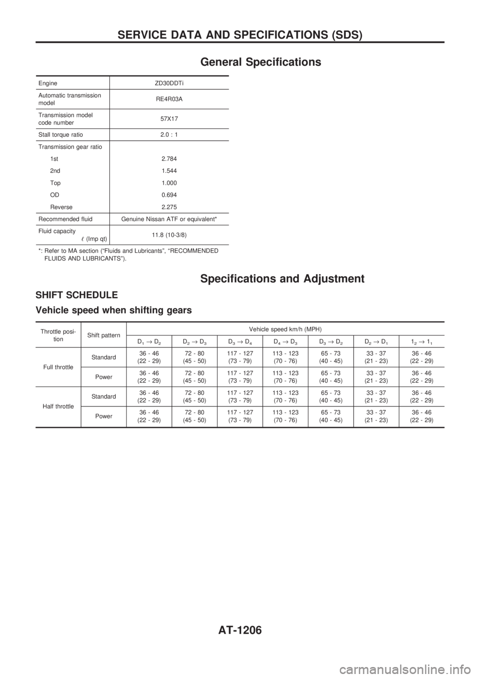
General Specifications
Engine ZD30DDTi
Automatic transmission
modelRE4R03A
Transmission model
code number57X17
Stall torque ratio 2.0 : 1
Transmission gear ratio
1st 2.784
2nd 1.544
Top 1.000
OD 0.694
Reverse 2.275
Recommended fluid Genuine Nissan ATF or equivalent*
Fluid capacity
!(Imp qt)11.8 (10-3/8)
*: Refer to MA section (ªFluids and Lubricantsº, ªRECOMMENDED
FLUIDS AND LUBRICANTSº).
Specifications and Adjustment
SHIFT SCHEDULE
Vehicle speed when shifting gears
Throttle posi-
tionShift patternVehicle speed km/h (MPH)
D
1®D2D2®D3D3®D4D4®D3D3®D2D2®D112®11
Full throttleStandard36-46
(22 - 29)72-80
(45 - 50)117 - 127
(73 - 79)113 - 123
(70 - 76)65-73
(40 - 45)33-37
(21 - 23)36-46
(22 - 29)
Power36-46
(22 - 29)72-80
(45 - 50)117 - 127
(73 - 79)113 - 123
(70 - 76)65-73
(40 - 45)33-37
(21 - 23)36-46
(22 - 29)
Half throttleStandard36-46
(22 - 29)72-80
(45 - 50)117 - 127
(73 - 79)113 - 123
(70 - 76)65-73
(40 - 45)33-37
(21 - 23)36-46
(22 - 29)
Power36-46
(22 - 29)72-80
(45 - 50)117 - 127
(73 - 79)113 - 123
(70 - 76)65-73
(40 - 45)33-37
(21 - 23)36-46
(22 - 29)
SERVICE DATA AND SPECIFICATIONS (SDS)
AT-1206
Page 880 of 1033
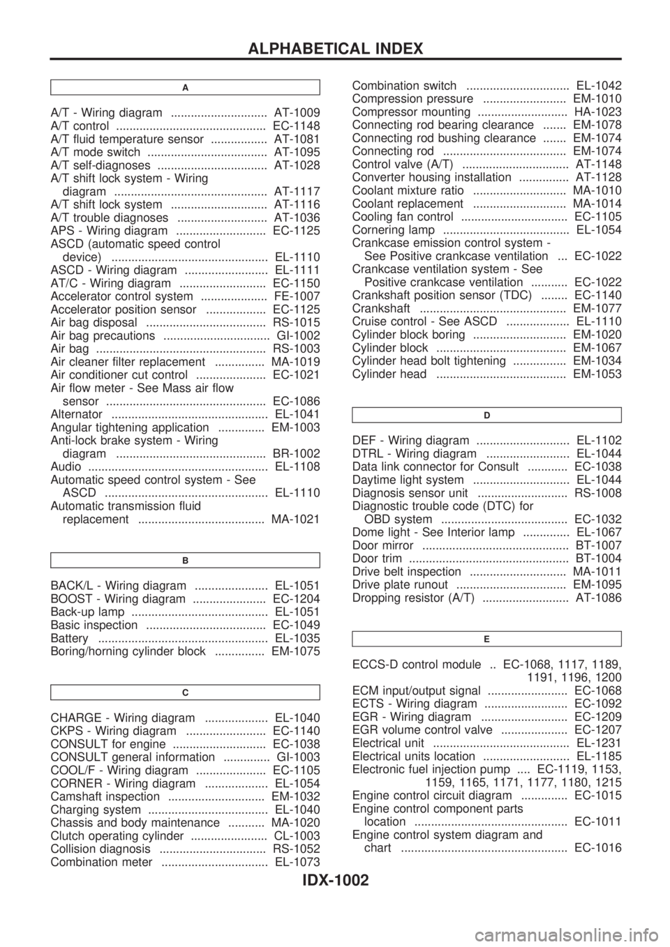
A
A/T - Wiring diagram ............................. AT-1009
A/T control ............................................. EC-1148
A/T fluid temperature sensor ................. AT-1081
A/T mode switch .................................... AT-1095
A/T self-diagnoses ................................. AT-1028
A/T shift lock system - Wiring
diagram .............................................. AT-1117
A/T shift lock system ............................. AT-1116
A/T trouble diagnoses ........................... AT-1036
APS - Wiring diagram ........................... EC-1125
ASCD (automatic speed control
device) ............................................... EL-1110
ASCD - Wiring diagram ......................... EL-1111
AT/C - Wiring diagram .......................... EC-1150
Accelerator control system .................... FE-1007
Accelerator position sensor .................. EC-1125
Air bag disposal .................................... RS-1015
Air bag precautions ................................ GI-1002
Air bag ................................................... RS-1003
Air cleaner filter replacement ............... MA-1019
Air conditioner cut control ..................... EC-1021
Air flow meter - See Mass air flow
sensor ................................................ EC-1086
Alternator ............................................... EL-1041
Angular tightening application .............. EM-1003
Anti-lock brake system - Wiring
diagram ............................................. BR-1002
Audio ...................................................... EL-1108
Automatic speed control system - See
ASCD ................................................. EL-1110
Automatic transmission fluid
replacement ...................................... MA-1021
B
BACK/L - Wiring diagram ...................... EL-1051
BOOST - Wiring diagram ...................... EC-1204
Back-up lamp ......................................... EL-1051
Basic inspection .................................... EC-1049
Battery ................................................... EL-1035
Boring/horning cylinder block ............... EM-1075
C
CHARGE - Wiring diagram ................... EL-1040
CKPS - Wiring diagram ........................ EC-1140
CONSULT for engine ............................ EC-1038
CONSULT general information .............. GI-1003
COOL/F - Wiring diagram ..................... EC-1105
CORNER - Wiring diagram ................... EL-1054
Camshaft inspection ............................. EM-1032
Charging system .................................... EL-1040
Chassis and body maintenance ........... MA-1020
Clutch operating cylinder ....................... CL-1003
Collision diagnosis ................................ RS-1052
Combination meter ................................ EL-1073Combination switch ............................... EL-1042
Compression pressure ......................... EM-1010
Compressor mounting ........................... HA-1023
Connecting rod bearing clearance ....... EM-1078
Connecting rod bushing clearance ....... EM-1074
Connecting rod ..................................... EM-1074
Control valve (A/T) ................................ AT-1148
Converter housing installation ............... AT-1128
Coolant mixture ratio ............................ MA-1010
Coolant replacement ............................ MA-1014
Cooling fan control ................................ EC-1105
Cornering lamp ...................................... EL-1054
Crankcase emission control system -
See Positive crankcase ventilation ... EC-1022
Crankcase ventilation system - See
Positive crankcase ventilation ........... EC-1022
Crankshaft position sensor (TDC) ........ EC-1140
Crankshaft ............................................ EM-1077
Cruise control - See ASCD ................... EL-1110
Cylinder block boring ............................ EM-1020
Cylinder block ....................................... EM-1067
Cylinder head bolt tightening ................ EM-1034
Cylinder head ....................................... EM-1053
D
DEF - Wiring diagram ............................ EL-1102
DTRL - Wiring diagram ......................... EL-1044
Data link connector for Consult ............ EC-1038
Daytime light system ............................. EL-1044
Diagnosis sensor unit ........................... RS-1008
Diagnostic trouble code (DTC) for
OBD system ...................................... EC-1032
Dome light - See Interior lamp .............. EL-1067
Door mirror ............................................ BT-1007
Door trim ................................................ BT-1004
Drive belt inspection ............................. MA-1011
Drive plate runout ................................. EM-1095
Dropping resistor (A/T) .......................... AT-1086
E
ECCS-D control module .. EC-1068, 1117, 1189,
1191, 1196, 1200
ECM input/output signal ........................ EC-1068
ECTS - Wiring diagram ......................... EC-1092
EGR - Wiring diagram .......................... EC-1209
EGR volume control valve .................... EC-1207
Electrical unit ......................................... EL-1231
Electrical units location .......................... EL-1185
Electronic fuel injection pump .... EC-1119, 1153,
1159, 1165, 1171, 1177, 1180, 1215
Engine control circuit diagram .............. EC-1015
Engine control component parts
location .............................................. EC-1011
Engine control system diagram and
chart .................................................. EC-1016
ALPHABETICAL INDEX
IDX-1002
Page 901 of 1033
![NISSAN PATROL 2000 Electronic Repair Manual Chassis and Body Maintenance
Abbreviations: R = Replace, I = Inspect: Correct or replace if necessary, L = Lubricate, T = Tighten, [ ] = At the specified mileage only
MAINTENANCE OPERATIONMAINTENANCE NISSAN PATROL 2000 Electronic Repair Manual Chassis and Body Maintenance
Abbreviations: R = Replace, I = Inspect: Correct or replace if necessary, L = Lubricate, T = Tighten, [ ] = At the specified mileage only
MAINTENANCE OPERATIONMAINTENANCE](/manual-img/5/57367/w960_57367-900.png)
Chassis and Body Maintenance
Abbreviations: R = Replace, I = Inspect: Correct or replace if necessary, L = Lubricate, T = Tighten, [ ] = At the specified mileage only
MAINTENANCE OPERATIONMAINTENANCE INTERVAL
Perform on a kilometer basis, but on an annual basis
when driving less than 15,000 km (9,000 miles) per
year.km x 1,000 15 30 45 60 75 90
(miles x 1,000) (9) (18) (27) (36) (45) (54)
Months 12 24 36 48 60 72
Underhood and under vehicleReference
pages
Headlamp aimingIIIIII Ð
When alignment (if necessary, balance & rotate wheels)IIIIII Ð
Brake pads, rotors & other brake componentsHIIIIII Ð
Foot brake, parking brake & clutch (for free play, stroke & operation)IIIIII Ð
Brake booster vacuum hoses, connections & check valve I I I Ð
Brake & clutch, systems and fluid (for level and leaks)IIIIII Ð
Brake fluidHRRRÐ
Power steering fluid and lines (for level and leaks)IIIIII Ð
Supplemental air bag systems See NOTE (1)RS-1007
Ventilation air filterHRRRÐ
Manual transmission oil (Inspect for leaks. Replace if leaks are found.)IIIII[R] Ð
Automatic transmission fluid (for level and leaks)HIIIIII Ð
Greasing point of propeller shaft See NOTE (2)LLLLLL Ð
Transfer fluid and limited-slip differential (LSD) gear oil (for
level & leaks or replace)HSee NOTE (3) I I I R I I Ð
Drive shafts & steering damperHIIIIII Ð
Front wheel bearing greaseHIRIRIR Ð
Front axle joint in knuckle flangeLLLÐ
Free-running hub greaseHIIIIII Ð
Body mounting bolts & nutsTTTTTT Ð
Steering gear & linkage, axle & suspension parts, propeller shaft & exhaust systemHIIIIII Ð
Body corrosion See NOTE (4)Ð
NOTE: (1) Inspect after 10 years, then every 2 years.
(2) The propeller shaft should be re-greased after being immersed in water.
(3) Including differential gear with differential lock.
(4) Inspect once per year.
HMaintenance items with ªHº should be performed more frequently according to ªMaintenance under severe driv-
ing conditionsº.
PERIODIC MAINTENANCE
MA-1003
Page 902 of 1033
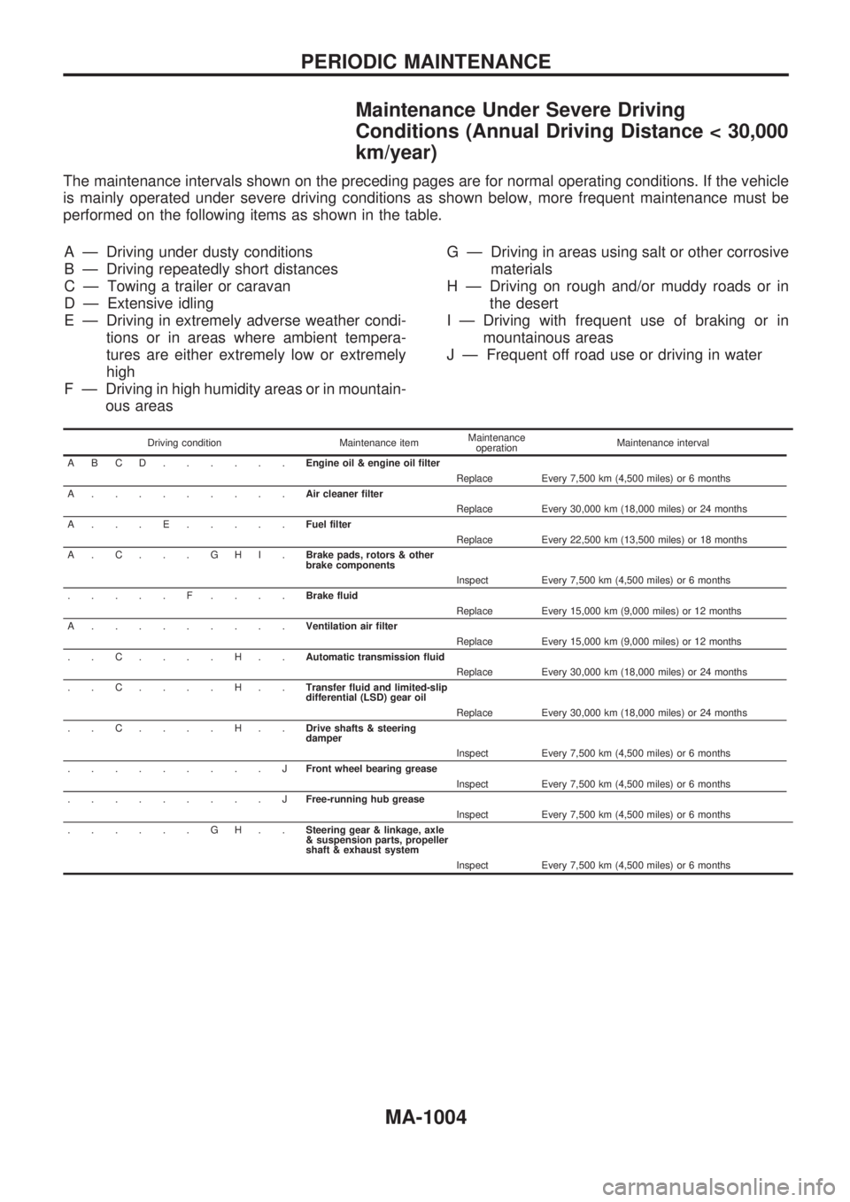
Maintenance Under Severe Driving
Conditions (Annual Driving Distance < 30,000
km/year)
The maintenance intervals shown on the preceding pages are for normal operating conditions. If the vehicle
is mainly operated under severe driving conditions as shown below, more frequent maintenance must be
performed on the following items as shown in the table.
A Ð Driving under dusty conditions
B Ð Driving repeatedly short distances
C Ð Towing a trailer or caravan
D Ð Extensive idling
E Ð Driving in extremely adverse weather condi-
tions or in areas where ambient tempera-
tures are either extremely low or extremely
high
F Ð Driving in high humidity areas or in mountain-
ous areasG Ð Driving in areas using salt or other corrosive
materials
H Ð Driving on rough and/or muddy roads or in
the desert
I Ð Driving with frequent use of braking or in
mountainous areas
J Ð Frequent off road use or driving in water
Driving condition Maintenance itemMaintenance
operationMaintenance interval
ABCD......Engine oil & engine oil filter
Replace Every 7,500 km (4,500 miles) or 6 months
A.........Air cleaner filter
Replace Every 30,000 km (18,000 miles) or 24 months
A...E.....Fuel filter
Replace Every 22,500 km (13,500 miles) or 18 months
A.C...GHI.Brake pads, rotors & other
brake components
Inspect Every 7,500 km (4,500 miles) or 6 months
.....F....Brake fluid
Replace Every 15,000 km (9,000 miles) or 12 months
A.........Ventilation air filter
Replace Every 15,000 km (9,000 miles) or 12 months
..C....H..Automatic transmission fluid
Replace Every 30,000 km (18,000 miles) or 24 months
..C....H..Transfer fluid and limited-slip
differential (LSD) gear oil
Replace Every 30,000 km (18,000 miles) or 24 months
..C....H..Drive shafts & steering
damper
Inspect Every 7,500 km (4,500 miles) or 6 months
.........JFront wheel bearing grease
Inspect Every 7,500 km (4,500 miles) or 6 months
.........JFree-running hub grease
Inspect Every 7,500 km (4,500 miles) or 6 months
......GH..Steering gear & linkage, axle
& suspension parts, propeller
shaft & exhaust system
Inspect Every 7,500 km (4,500 miles) or 6 months
PERIODIC MAINTENANCE
MA-1004