2000 MITSUBISHI MONTERO fuel pump
[x] Cancel search: fuel pumpPage 614 of 1839

DIESEL FUEL <4D5-stepIII>-Service Specifications/Sealant13E-4
SERVICE SPECIFICATIONS
ItemStandard value
Fuel injection initial pressure kPa14,710 - 15,490
Accelerator pedal position sensor reference voltage V0.985 - 1.085
Accelerator pedal position sensor resistance kΩ3.5 - 6.5
Boost air temperature sensor (Intake air temperature
)itkΩ
When the temperature is 20_C2.3 - 3.0p(p
sensor) resistance kΩWhen the temperature is 80_C0.30 - 0.42
Engine coolant temperature sensor resistance kΩWhen the temperature is 20_C2.1 - 2.7gp
When the temperature is 80_C0.26 - 0.36
Fuel cut solenoid valve resistanceΩ6.8 - 9.2
Timing control valve resistanceΩ10.8 - 11.2
Timer piston position sensor resistanceΩConnector terminals No. 1 - No. 2160 - 168pp
Connector terminals No. 1 - No. 380 - 84
Connector terminals No. 2 - No. 380 - 84
Control sleeve position sensor resistanceΩConnector terminals No. 4 - No. 1211.2 - 12.4p
Connector terminals No. 4 - No. 85.6 - 6.2
Connector terminals No. 8 - No. 125.6 - 6.2
GE actuator (electronic governor) resistanceΩConnector terminals No. 6 - No. 100.64 - 0.72
Fuel temperature sensor resistance kΩConnector terminals No. 7 - No. 111.4 - 2.6
Pump speed sensor resistance kΩ1.36 - 1.84
Throttle solenoid valve resistanceΩ36 - 44
SEALANT
ItemSpecified sealant
Engine coolant temperature sensor3M Nut Locking Part No. 4171 or equivalent
www.WorkshopManuals.co.uk
Purchased from www.WorkshopManuals.co.uk
Page 618 of 1839

DIESEL FUEL <4D5-stepIII>-Troubleshooting13E-8
INSPECTION CHART FOR DIAGNOSIS CODES
Code No.Diagnosis itemReference
page
11Accelerator pedal position sensor (main) system13E-9
12*Boost pressure sensor system13E-10
13Barometric pressure sensor (ECU built-in) system13E-11
14Fuel temperature sensor system13E-11
15Engine coolant temperature sensor system13E-12
16Boost air temperature sensor system13E-12
17Vehicle speed sensor system13E-13
18Pump speed sensor system13E-14
21Crank angle sensor system13E-15
23Idle switch (accelerator pedal position sensor built-in) system13E-16
25*Timer piston position sensor system13E-17
26*Control sleeve position sensor system13E-18
27Accelerator pedal position sensor (sub) system13E-19
41*Throttle solenoid valve system13E-20
43Timing control valve system13E-21
46Injection volume adjusting ROM system13E-22
48*GE actuator (in the middle of control sleeve position sensor inoperative) system13E-23
49*Over boost (variable geometry control pressure sensor system malfunction)13E-24
51EGR valve position sensor system13E-25
52Variable geometry control pressure sensor system13E-26
54Immobilizer system13E-27
Caution
If the above-mentioned diagnosis code number with the asterisks can be displayed along with another
code number in parentheses simultaneously, check the other code number before replacing the
engine-ECU.
12 (41, 49), 26 (48), 25 (43), 41 (12, 49), 48 (26), 49 (12, 41)
www.WorkshopManuals.co.uk
Purchased from www.WorkshopManuals.co.uk
Page 621 of 1839
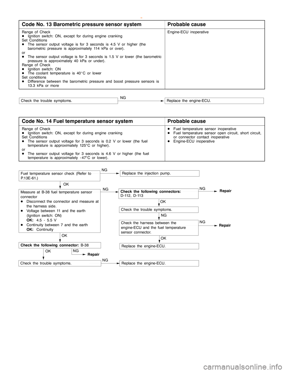
DIESEL FUEL <4D5-stepIII>-Troubleshooting13E-11
Code No. 13 Barometric pressure sensor systemProbable cause
Range of Check
DIgnition switch: ON, except for during engine cranking
Set Conditions
DThe sensor output voltage is for 3 seconds is 4.5 V or higher (the
barometric pressure is approximately 114 kPa or over).
or
DThe sensor output voltage is for 3 seconds is 1.5 V or lower (the barometric
pressure is approximately 40 kPa or under).
Range of Check
DIgnition switch: ON
DThe coolant temperature is 40_C or lower
Set conditions
DDifference between the barometric pressure and boost pressure sensors is
13.3 kPa or moreEngine-ECU inoperative
Replace the engine-ECU.NGCheck the trouble symptoms.
Code No. 14 Fuel temperature sensor systemProbable cause
Range of Check
DIgnition switch: ON, except for during engine cranking
Set Conditions
DThe sensor output voltage for 3 seconds is 0.2 V or lower (the fuel
temperature is approximately 125°C or higher).
or
DThe sensor output voltage for 3 seconds is 4.6 V or higher (the fuel
temperature is approximately - 47°C or lower).DFuel temperature sensor inoperative
DFuel temperature sensor open circuit, short circuit,
or connector contact inoperative
DEngine-ECU inoperative
OK
Measure at B-38 fuel temperature sensor
connector
DDisconnect the connector and measure at
the harness side.
DVoltage between 11 and the earth
(Ignition switch: ON)
OK:4.5 - 5.5 V
DContinuity between 7 and the earth
OK:ContinuityNGCheck the following connectors:
D-112, D-113NG
Repair
OK
OK
Check the harness between the
engine-ECU and the fuel temperature
sensor connector.Repair
NG
Check the trouble symptoms.
Replace the engine-ECU.NG
Replace the engine-ECU.OKNG
Replace the injection pump.
OK
Repair
Check the following connector:B-38
NG
NGCheck the trouble symptoms.
Fuel temperature sensor check (Refer to
P.13E-61.)
www.WorkshopManuals.co.uk
Purchased from www.WorkshopManuals.co.uk
Page 624 of 1839
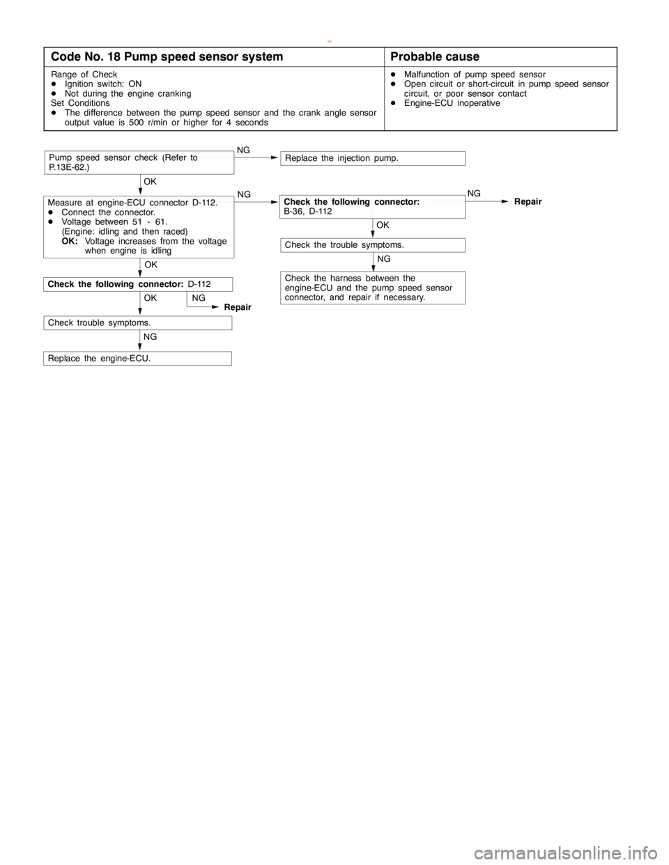
DIESEL FUEL <4D5-stepIII>-Troubleshooting13E-14
Code No. 18 Pump speed sensor systemProbable cause
Range of Check
DIgnition switch: ON
DNot during the engine cranking
Set Conditions
DThe difference between the pump speed sensor and the crank angle sensor
output value is 500 r/min or higher for 4 secondsDMalfunction of pump speed sensor
DOpen circuit or short-circuit in pump speed sensor
circuit, or poor sensor contact
DEngine-ECU inoperative
NG
Replace the engine-ECU.OK
Check trouble symptoms.NG
Repair
NG
Check the harness between the
engine-ECU and the pump speed sensor
connector, and repair if necessary.
OK
Replace the injection pump.
OK
Measure at engine-ECU connector D-112.
DConnect the connector.
DVoltage between 51 - 61.
(Engine: idling and then raced)
OK:Voltage increases from the voltage
when engine is idlingNGCheck the following connector:
B-36, D-112NG
Repair
OK
NGPump speed sensor check (Refer to
P.13E-62.)
Check the following connector:D-112
Check the trouble symptoms.
www.WorkshopManuals.co.uk
Purchased from www.WorkshopManuals.co.uk
Page 625 of 1839
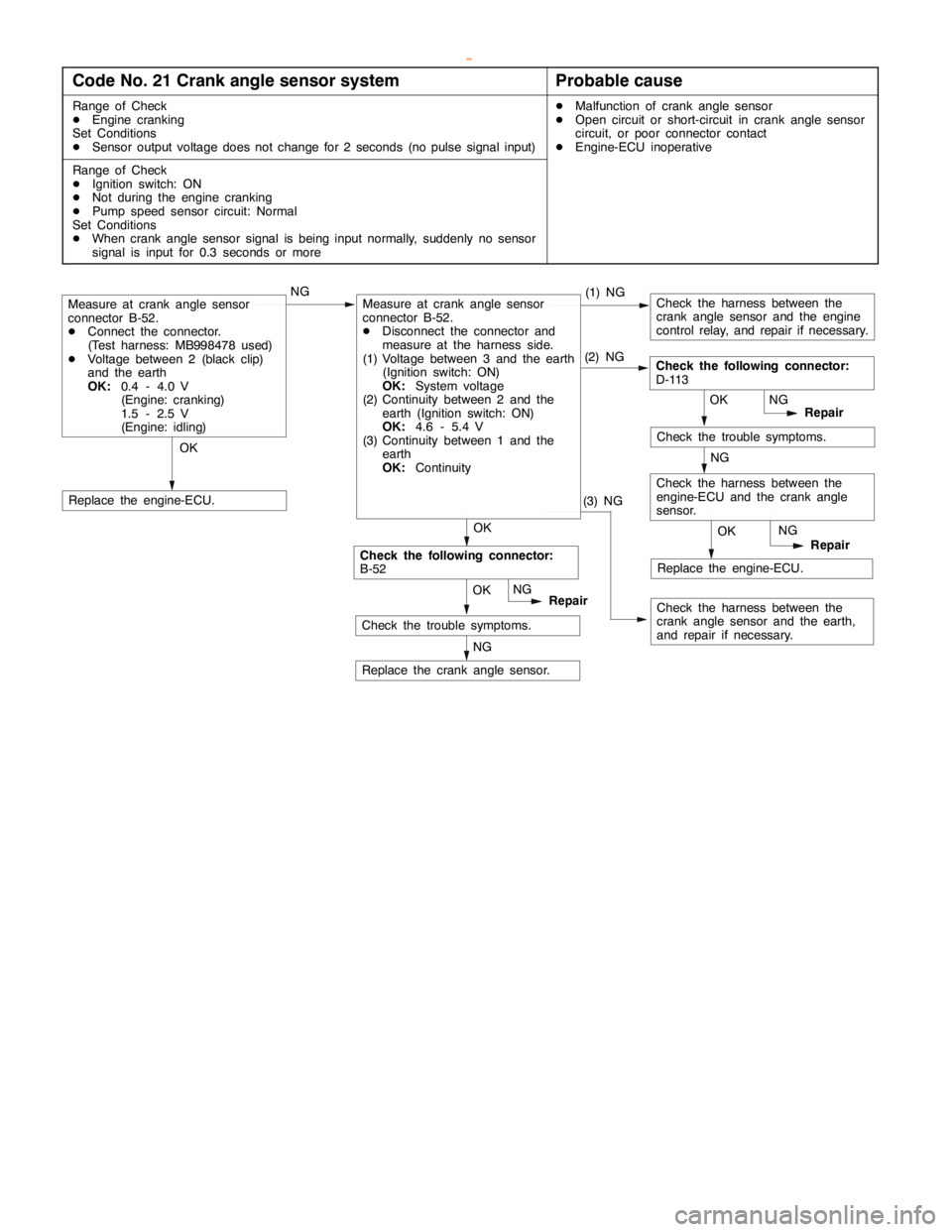
DIESEL FUEL <4D5-stepIII>-Troubleshooting13E-15
Code No. 21 Crank angle sensor systemProbable cause
Range of Check
DEngine cranking
Set Conditions
DSensor output voltage does not change for 2 seconds (no pulse signal input)DMalfunction of crank angle sensor
DOpen circuit or short-circuit in crank angle sensor
circuit, or poor connector contact
DEngine-ECU inoperative
Range of Check
DIgnition switch: ON
DNot during the engine cranking
DPump speed sensor circuit: Normal
Set Conditions
DWhen crank angle sensor signal is being input normally, suddenly no sensor
signal is input for 0.3 seconds or more
OK
Check the harness between the
crank angle sensor and the engine
control relay, and repair if necessary.
OKNG(1) NGMeasure at crank angle sensor
connector B-52.
DConnect the connector.
(Test harness: MB998478 used)
DVoltage between 2 (black clip)
and the earth
OK:0.4 - 4.0 V
(Engine: cranking)
1.5 - 2.5 V
(Engine: idling)
NG
Replace the crank angle sensor.
Replace the engine-ECU.
OKRepair
Check the following connector:
D-113
NG
OK
Repair NG
Check the harness between the
engine-ECU and the crank angle
sensor.NG
Check the trouble symptoms.
Replace the engine-ECU.
Check the harness between the
crank angle sensor and the earth,
and repair if necessary. OKRepair NG
Check the following connector:
B-52
Check the trouble symptoms.
Measure at crank angle sensor
connector B-52.
DDisconnect the connector and
measure at the harness side.
(1) Voltage between 3 and the earth
(Ignition switch: ON)
OK:System voltage
(2) Continuity between 2 and the
earth (Ignition switch: ON)
OK:4.6 - 5.4 V
(3) Continuity between 1 and the
earth
OK:Continuity(2) NG
(3) NG
www.WorkshopManuals.co.uk
Purchased from www.WorkshopManuals.co.uk
Page 627 of 1839
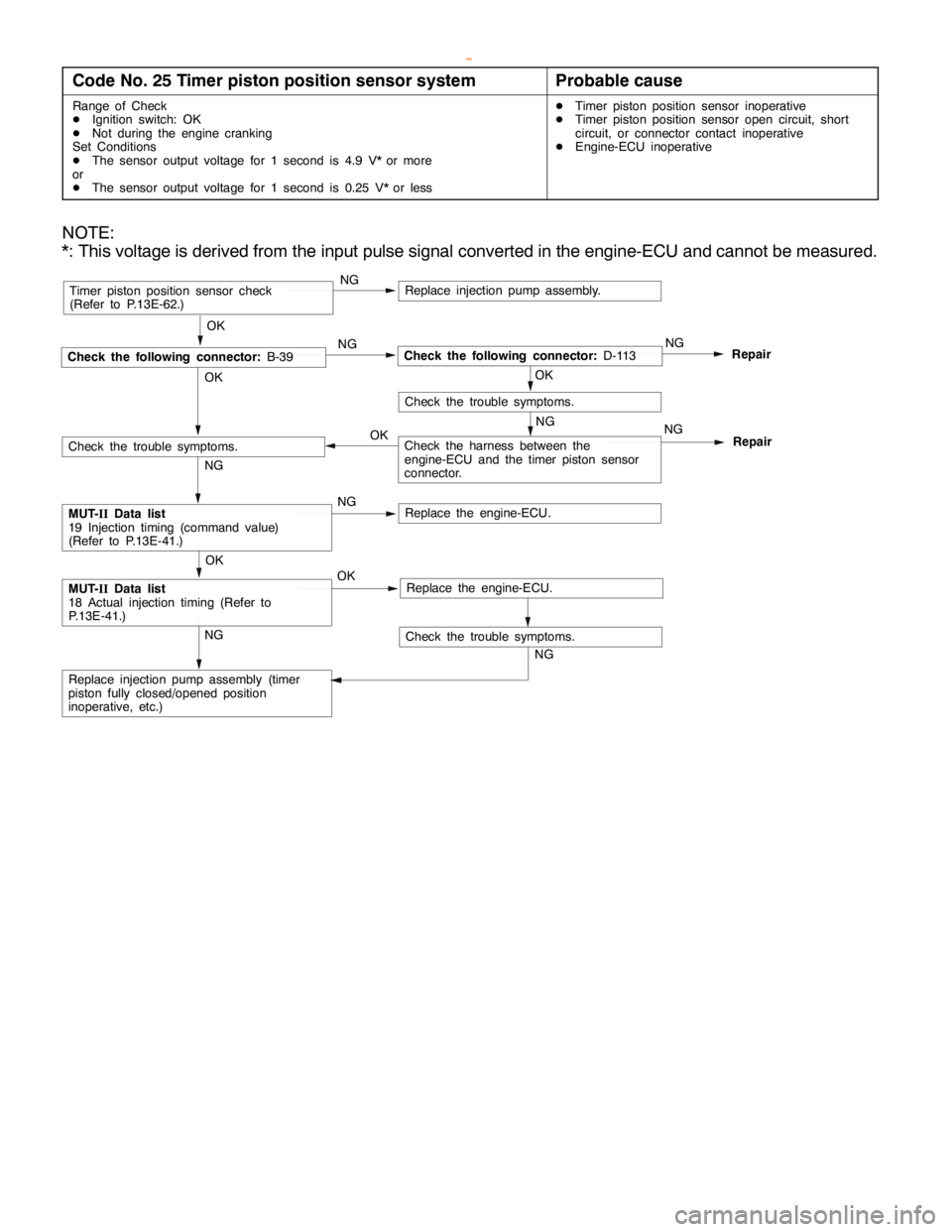
DIESEL FUEL <4D5-stepIII>-Troubleshooting13E-17
Code No. 25 Timer piston position sensor systemProbable cause
Range of Check
DIgnition switch: OK
DNot during the engine cranking
Set Conditions
DThe sensor output voltage for 1 second is 4.9 V* or more
or
DThe sensor output voltage for 1 second is 0.25 V* or lessDTimer piston position sensor inoperative
DTimer piston position sensor open circuit, short
circuit, or connector contact inoperative
DEngine-ECU inoperative
NOTE:
*: This voltage is derived from the input pulse signal converted in the engine-ECU and cannot be measured.
Replace injection pump assembly (timer
piston fully closed/opened position
inoperative, etc.)
NG
NG
OK
OK
NG
Check the following connector:D-113NG
Repair
OK
Repair
NGTimer piston position sensor check
(Refer to P.13E-62.)
NG
NG OK
NG
Check the trouble symptoms.
Replace injection pump assembly.
Check the following connector:B-39
OK
Replace the engine-ECU.NGMUT-IIData list
19 Injection timing (command value)
(Refer to P.13E-41.)
OK
Check the trouble symptoms.
Check the trouble symptoms.
Check the harness between the
engine-ECU and the timer piston sensor
connector.
MUT-IIData list
18 Actual injection timing (Refer to
P.13E-41.)Replace the engine-ECU.
www.WorkshopManuals.co.uk
Purchased from www.WorkshopManuals.co.uk
Page 628 of 1839
DIESEL FUEL <4D5-stepIII>-Troubleshooting13E-18
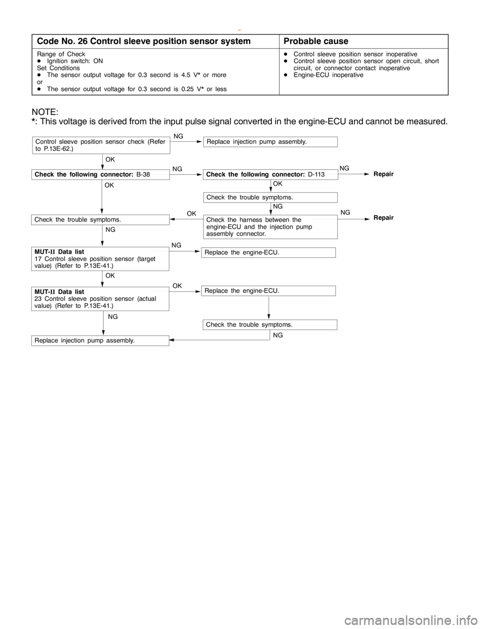
Code No. 26 Control sleeve position sensor systemProbable cause
Range of Check
DIgnition switch: ON
Set Conditions
DThe sensor output voltage for 0.3 second is 4.5 V* or more
or
DThe sensor output voltage for 0.3 second is 0.25 V* or lessDControl sleeve position sensor inoperative
DControl sleeve position sensor open circuit, short
circuit, or connector contact inoperative
DEngine-ECU inoperative
NOTE:
*: This voltage is derived from the input pulse signal converted in the engine-ECU and cannot be measured.
OK
NG
Check the following connector:D-113NG
Repair
OK
Repair
NGControl sleeve position sensor check (Refer
to P.13E-62.)
NG
NG OK
NG
Check the trouble symptoms.
Replace injection pump assembly.
Check the following connector:B-38
OK
Replace the engine-ECU.NGMUT-IIData list
17 Control sleeve position sensor (target
value) (Refer to P.13E-41.)
OK
Check the trouble symptoms.
Replace injection pump assembly.
Check the trouble symptoms.
NG
NG
Check the harness between the
engine-ECU and the injection pump
assembly connector.
MUT-IIData list
23 Control sleeve position sensor (actual
value) (Refer to P.13E-41.)Replace the engine-ECU. OK
www.WorkshopManuals.co.uk
Purchased from www.WorkshopManuals.co.uk
Page 631 of 1839
DIESEL FUEL <4D5-stepIII>-Troubleshooting13E-21
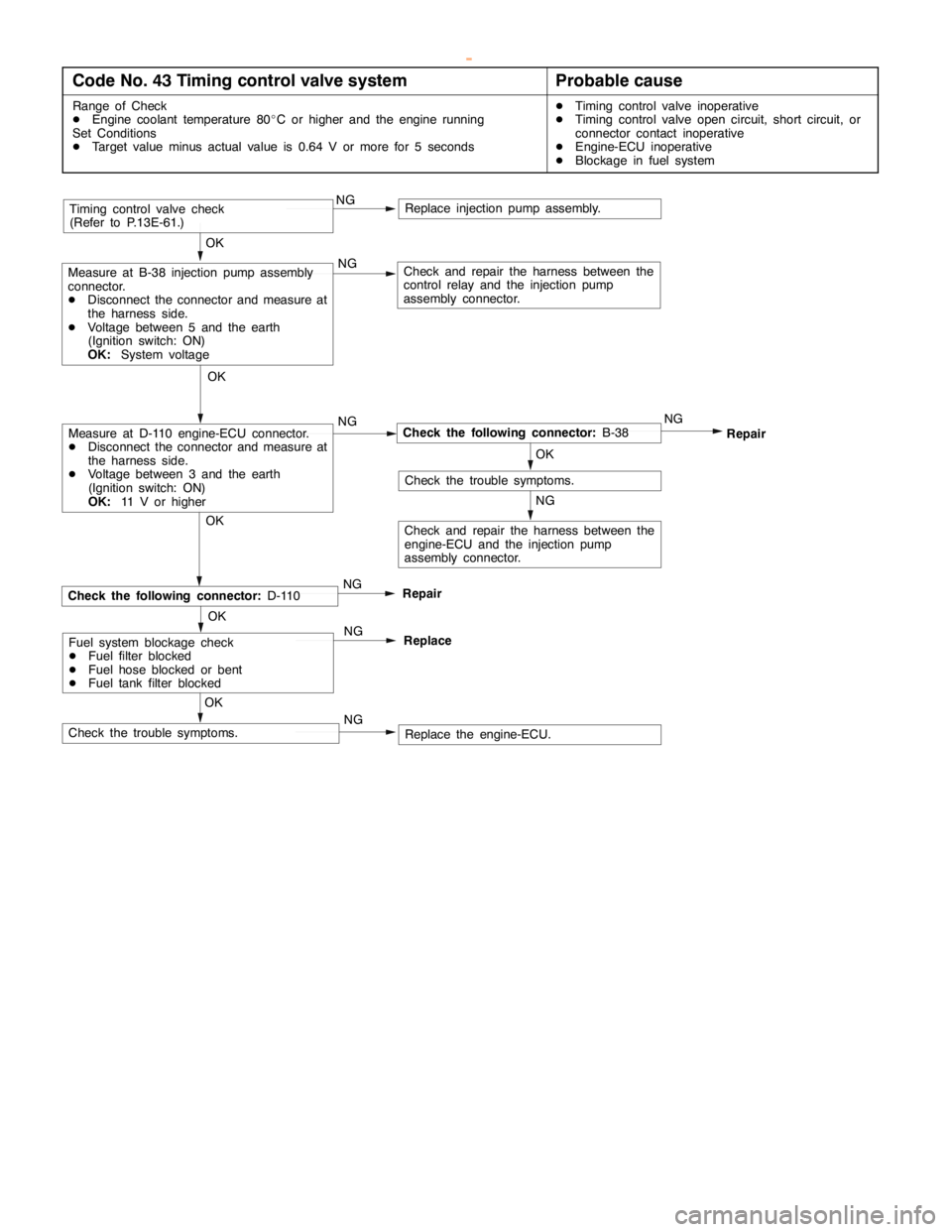
Code No. 43 Timing control valve systemProbable cause
Range of Check
DEngine coolant temperature 80_C or higher and the engine running
Set Conditions
DTarget value minus actual value is 0.64 V or more for 5 secondsDTiming control valve inoperative
DTiming control valve open circuit, short circuit, or
connector contact inoperative
DEngine-ECU inoperative
DBlockage in fuel system
OK
OK
Check and repair the harness between the
control relay and the injection pump
assembly connector.
Timing control valve check
(Refer to P.13E-61.)
Replace the engine-ECU. OK
RepairCheck the following connector:D-110
Check the trouble symptoms.NG NG NG
Check the following connector:B-38NG
Repair
OK
Check the trouble symptoms.
NG
NGMeasure at D-110 engine-ECU connector.
DDisconnect the connector and measure at
the harness side.
DVoltage between 3 and the earth
(Ignition switch: ON)
OK:11 V or higherOK
Measure at B-38 injection pump assembly
connector.
DDisconnect the connector and measure at
the harness side.
DVoltage between 5 and the earth
(Ignition switch: ON)
OK:System voltage
Replace injection pump assembly.
Check and repair the harness between the
engine-ECU and the injection pump
assembly connector.
Fuel system blockage check
DFuel filter blocked
DFuel hose blocked or bent
DFuel tank filter blockedOK
Replace NG
NG
www.WorkshopManuals.co.uk
Purchased from www.WorkshopManuals.co.uk