2000 MITSUBISHI MONTERO sensor
[x] Cancel search: sensorPage 270 of 1839
GDI -Troubleshooting
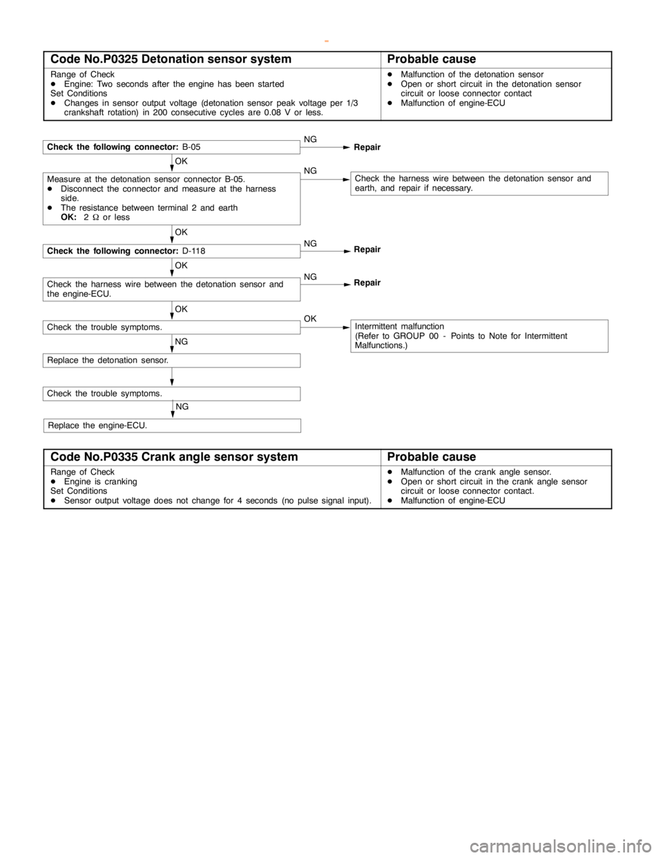
Code No.P0325 Detonation sensor systemProbable cause
Range of Check
DEngine: Two seconds after theengine has beenstarted
Set Conditions
DChanges in sensor output voltage (detonation sensor peak voltage per 1/3
crankshaft rotation) in 200 consecutivecycles are0.08 V or less.DMalfunction of the detonation sensor
DOpen or short circuit in the detonation sensor
circuit or loose connector contact
DMalfunction of engine-ECU
Check the following connector:
B-05NG
Repair
OK
Measure at the detonation sensor connector B-05.
DDisconnect the connector and measure at the harness
side.
DThe resistance between terminal 2 and earth
OK:
2Wor lessNGCheck the harness wire between the detonation sensor and
earth, and repair if necessary.
OK
Check the following connector:
D-118NG
Repair
OK
Check the harness wire between the detonation sensor and
the engine-ECU.NG
Repair
OK
Check the trouble symptoms.OKIntermittent malfunction
(Refer to GROUP 00 - Points to Note for Intermittent
Malfunctions.)
NG
Replace the detonation sensor.
Check the trouble symptoms.
NG
Replace the engine-ECU.
Code No.P0335 Crank angle sensor systemProbable cause
Range of Check
DEngine is cranking
Set Conditions
DSensor output voltage does not change for 4 seconds (no pulse signal input).DMalfunction of the crankanglesensor.
DOpen or short circuit in the crankanglesensor
circuit or loose connector contact.
DMalfunction of engine-ECU
www.WorkshopManuals.co.uk
Purchased from www.WorkshopManuals.co.uk
Page 271 of 1839
GDI -Troubleshooting
OK
Check the harness wire between the
crankanglesensor and the
engine-ECU, and repair if necessary.
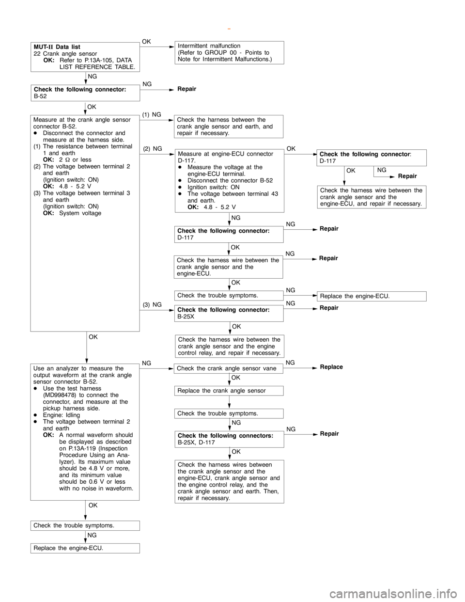
MUT-
IIData list
22 Crankanglesensor
OK:
Refer to P.13A-105, DATA
LIST REFERENCE TABLE.OKIntermittent malfunction
(Refer to GROUP 00 - Points to
Note for Intermittent Malfunctions.)
OK
Measure at the crankanglesensor
connector B-52.
DDisconnect the connector and
measure at the harness side.
(1) The resistance between terminal
1 and earth
OK:
2Wor less
(2) The voltage between terminal 2
and earth
(Ignition switch: ON)
OK:
4.8 - 5.2 V
(3) The voltage between terminal 3
and earth
(Ignition switch: ON)
OK:
System voltage(1) NGCheck the harness between the
crankanglesensor and earth, and
repair if necessary.
NG
Repair
NG
Check the following connector:
D-117NG
Repair
NG
Check the following connector:
B-52NG
Repair
(2) NGMeasure at engine-ECU connector
D-117.
DMeasure the voltage at the
engine-ECU terminal.
DDisconnect the connector B-52
DIgnition switch: ON
DThe voltage between terminal 43
and earth.
OK:
4.8 - 5.2 VOKCheck the following connector
:
D-117
Check the following connector:
B-25XNG
Repair
OK
Check the harness wire between the
crankanglesensor and the
engine-ECU.NG
Repair
OK
Check the trouble symptoms.NGReplace the engine-ECU.
(3) NG
OK
Check the harness wire between the
crankanglesensor and theengine
control relay, and repair if necessary.OK
Use an analyzer to measure the
output waveform at the crankangle
sensor connector B-52.
DUse the test harness
(MD998478) to connect the
connector, and measure at the
pickup harness side.
DEngine: Idling
DThe voltage between terminal 2
and earth
OK:
A normal waveform should
be displayed as described
on P.13A-119 (Inspection
Procedure Using an Ana-
lyzer). Its maximum value
should be 4.8 V or more,
and its minimumvalue
should be 0.6 V or less
with no noise in waveform.NGCheck the crankanglesensor vaneNG
Replace
OK
Replace the crankanglesensor
Check the trouble symptoms.
NG
Check the following connectors:
B-25X, D-117NG
Repair
OK
Check the harness wires between
the crankanglesensor and the
engine-ECU, crankanglesensor and
the engine controlrelay, and the
crankanglesensor and earth. Then,
repair if necessary.
OK
Check the trouble symptoms.
NG
Replace the engine-ECU.
www.WorkshopManuals.co.uk
Purchased from www.WorkshopManuals.co.uk
Page 272 of 1839

GDI -Troubleshooting
Code No.P0340 Camshaft position sensor systemProbable cause
Range of Check
DAfter theengine wasstarted
Set Conditions
DThe sensor output voltage does not change for 4 seconds (no pulse signal
input).DMalfunction of the camshaft position sensor
DOpen or short circuit in the camshaft position
sensor circuit or loose connector contact.
DMalfunction of engine-ECU
www.WorkshopManuals.co.uk
Purchased from www.WorkshopManuals.co.uk
Page 273 of 1839
GDI -Troubleshooting
OK
Check the harness wire between the
intermediate connector and the
engine-ECU, and repair if necessary.NG
Repair
NG
NG
Repair
NG
Repair
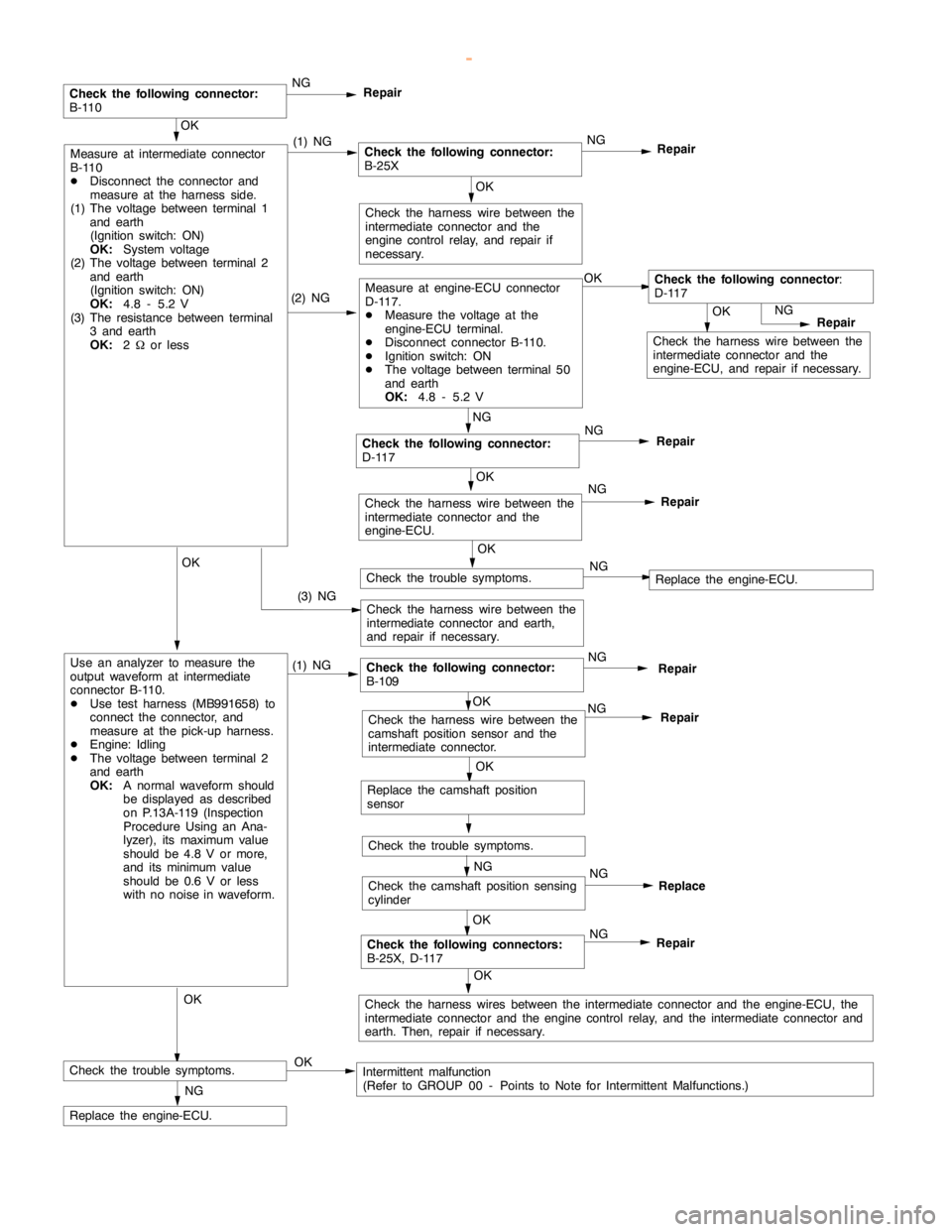
(2) NGMeasure at engine-ECU connector
D-117.
DMeasure the voltage at the
engine-ECU terminal.
DDisconnect connector B-110.
DIgnition switch: ON
DThe voltage between terminal 50
and earth
OK:
4.8 - 5.2 VOKCheck the following connector
:
D-117
Check the harness wire between the
intermediate connector and earth,
and repair if necessary.
OK
Check the harness wire between the
intermediate connector and the
engine controlrelay, and repair if
necessary.
(3) NG
OK
Measure at intermediate connector
B-110
DDisconnect the connector and
measure at the harness side.
(1) The voltage between terminal 1
and earth
(Ignition switch: ON)
OK:
System voltage
(2) The voltage between terminal 2
and earth
(Ignition switch: ON)
OK:
4.8 - 5.2 V
(3) The resistance between terminal
3 and earth
OK:
2Wor less(1) NGCheck the following connector:
B-25XNG
Repair
OK
Replace the camshaft position
sensor
Check the trouble symptoms.
OK
NG
Repair
OK
Check the harness wires between the intermediate connector and the engine-ECU, the
intermediate connector and theengine controlrelay, and the intermediate connector and
earth. Then, repair if necessary.
NG
Replace the engine-ECU.
OK
Check the harness wire between the
intermediate connector and the
engine-ECU.NG
Repair
OK
Use an analyzer to measure the
output waveform at intermediate
connector B-110.
DUse test harness (MB991658) to
connect the connector, and
measure at the pick-up harness.
DEngine: Idling
DThe voltage between terminal 2
and earth
OK:
A normal waveform should
be displayed as described
on P.13A-119 (Inspection
Procedure Using an Ana-
lyzer), its maximum value
should be 4.8 V or more,
and its minimumvalue
should be 0.6 V or less
with no noise in waveform.(1) NGCheck the following connector:
B-109NG
Repair
OK
Check the harness wire between the
camshaft position sensor and the
intermediate connector.NG
Repair
NG
Check the camshaft position sensing
cylinderNG
OK
Check the trouble symptoms.Intermittent malfunction
(Refer to GROUP 00 - Points to Note for Intermittent Malfunctions.)
OK
Check the trouble symptoms.NGReplace the engine-ECU.
Replace
OK
Check the following connector:
B-110
Check the following connector:
D-117
Check the following connectors:
B-25X, D-117
www.WorkshopManuals.co.uk
Purchased from www.WorkshopManuals.co.uk
Page 275 of 1839
GDI -Troubleshooting
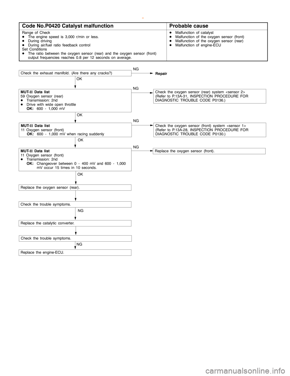
Code No.P0420 Catalyst malfunctionProbable cause
Range of Check
DThe enginespeed is 3,000 r/min or less.
DDuring driving
DDuring air/fuel ratio feedback control
Set Conditions
DThe ratio between the oxygen sensor (rear) and the oxygen sensor (front)
output frequencies reaches 0.8 per 12 seconds on average.DMalfunction of catalyst
DMalfunction of the oxygen sensor (front)
DMalfunction of the oxygen sensor (rear)
DMalfunction of engine-ECU
Check the trouble symptoms.
Check the exhaust manifold. (Are there anycracks?)NG
OK
MUT-
IIData list
59 Oxygen sensor (rear)
DTransmission: 2nd
DDrive with wideopen throttle
OK:
600 - 1,000 mVNGCheck the oxygen sensor (rear) system
(Refer to P.13A-31, INSPECTIONPROCEDURE FOR
DIAGNOSTIC TROUBLE CODE P0136.)
OK
MUT-
IIData list
11 Oxygen sensor (front)
DTransmission: 2nd
OK:
Changeover between 0 - 400 mV and 600 - 1,000
mV occur 15 times in 10 seconds.
OK
Replace the oxygen sensor (rear).
NG
Replace the catalytic converter.
Check the trouble symptoms.
NG
Replace the engine-ECU.
MUT-
IIData list
11 Oxygen sensor (front)
OK:
600 - 1,000 mV when racing suddenly
OK
NGRepair
Check the oxygen sensor (front) system
(Refer to P.13A-28, INSPECTIONPROCEDURE FOR
DIAGNOSTIC TROUBLE CODE P0130.)
Replace the oxygen sensor (front). NG
www.WorkshopManuals.co.uk
Purchased from www.WorkshopManuals.co.uk
Page 277 of 1839
GDI -Troubleshooting
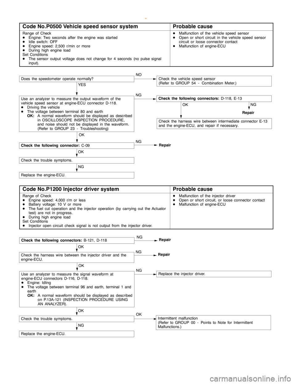
Code No.P0500 Vehicle speed sensor systemProbable cause
Range of Check
DEngine: Two seconds after theengine wasstarted
DIdle switch: OFF
DEngine speed: 2,500 r/min or more
DDuring high engine load
Set Conditions
DThe sensor output voltage does not change for 4 seconds (no pulse signal
input).DMalfunction of the vehicle speed sensor
DOpen or short circuit in the vehicle speed sensor
circuit or loose connector contact
DMalfunction of engine-ECU
NOCheck the vehicle speed sensor
(Refer to GROUP 54 - Combination Meter.)
YES
Use an analyzer to measure the output waveform of the
vehicle speed sensor at engine-ECU connector D-118.
DDriving the vehicle
DThe voltage between terminal 80 and earth
OK:
A normal waveform should be displayed as described
in OSCILLOSCOPE INSPECTION PROCEDURE,
and noise should not be displayed in the waveform.
(Refer to GROUP 23 - Troubleshooting)NGCheck the following connectors:
D-118, E-13
NG
Repair
OK
Check the harness wire between intermediate connector E-13
and the engine-ECU, and repair if necessary.
OK
Check the following connector:
C-09NG
Repair
OK
Check the trouble symptoms.
NG
Replace the engine-ECU.
Does the speedometer operate normally?
Code No.P1200 Injector driver systemProbable cause
Range of Check
DEngine speed: 4,000 r/m or less
DBattery voltage: 10 V or more
DThe fuel cut operation and the injector operation (by carrying out the Actuator
test) are not in progress.
DDuring high engine load
Set Conditions
DInjector opencircuit check signal is not output from the injector driver.DMalfunction of the injector driver
DOpen or short circuit, or loose connector contact
DMalfunction of engine-ECU
OK
Use an analyzer to measure the signal waveform at
engine-ECU connectors D-116, D-118.
DEngine: Idling
DThe voltage between terminal 96 and earth, terminal 1 and
earth
OK:
A normal waveform should be displayed as described
on P.13A-121 (INSPECTIONPROCEDURE USING
AN ANALYZER).NGReplace the injector driver.
OK
Check the harness wire between the injector driver and the
engine-ECU.NG
Repair
NG
Replace the engine-ECU.
Check the following connectors:
B-121, D-118NG
Repair
OK
Check the trouble symptoms.OKIntermittent malfunction
(Refer to GROUP 00 - Points to Note for Intermittent
Malfunctions.)
www.WorkshopManuals.co.uk
Purchased from www.WorkshopManuals.co.uk
Page 278 of 1839
GDI -Troubleshooting
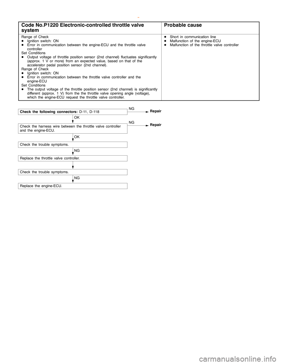
Code No.P1220 Electronic-controlled throttle valve
systemProbable cause
Range of Check
DIgnition switch: ON
DError in communication between the engine-ECU and the throttle valve
controller
Set Conditions
DOutput voltage of throttle position sensor (2nd channel) fluctuates significantly
(approx. 1 V or more) from an expected value, based on that of the
accelerator pedal positionsensor (2nd channel).
Range of Check
DIgnition switch: ON
DError in communication between the throttle valve controller and the
engine-ECU
Set Conditions
DThe output voltage of the throttle position sensor (2nd channel) is significantly
different (approx. 1 V) from the the throttle valveopening angle (voltage),
which the engine-ECU request the throttle valve controller.DShort in communicationline
DMalfunction of the engine-ECU
DMalfunction of the throttle valve controller
OK
Check the harness wire between the throttle valve controller
and the engine-ECU.NG
Repair
NG
Replace the engine-ECU.
Check the following connectors:
D-11, D-118NG
Repair
OK
NG
Replace the throttle valve controller.
Check the trouble symptoms.
Check the trouble symptoms.
www.WorkshopManuals.co.uk
Purchased from www.WorkshopManuals.co.uk
Page 279 of 1839
GDI -Troubleshooting
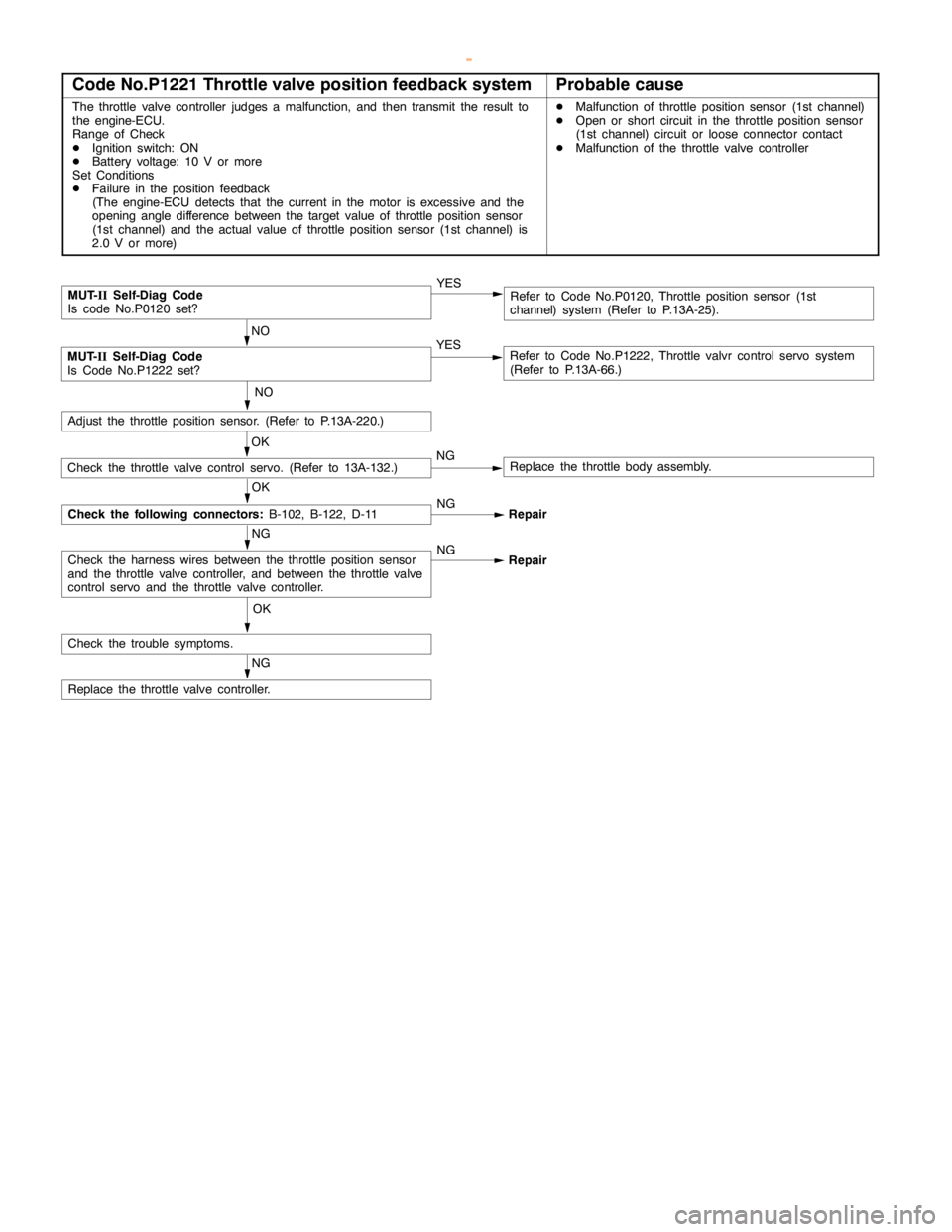
Code No.P1221 Throttle valve position feedback systemProbable cause
The throttle valve controller judges a malfunction, and then transmit the result to
the engine-ECU.
Range of Check
DIgnition switch: ON
DBattery voltage: 10 V or more
Set Conditions
DFailure in the position feedback
(The engine-ECU detects that the current in the motor isexcessive and the
opening angle difference between the targetvalue of throttle position sensor
(1st channel) and the actual value of throttle position sensor (1st channel) is
2.0 V or more)DMalfunction of throttle position sensor (1st channel)
DOpen or short circuit in the throttle position sensor
(1st channel) circuit or loose connector contact
DMalfunction of the throttle valve controller
NG
Replace the throttle valve controller.
OK
Check the trouble symptoms.
NG
Check the harness wires between the throttle position sensor
and the throttle valve controller, and between the throttle valve
control servo and the throttle valve controller.NG
Repair
NO
Adjust the throttle position sensor. (Refer to P.13A-220.)
MUT-
IISelf-Diag Code
Is code No.P0120 set?YESRefer to Code No.P0120, Throttle position sensor (1st
channel) system (Refer to P.13A-25).
NO
MUT-
IISelf-Diag Code
Is Code No.P1222 set?YESRefer to Code No.P1222, Throttle valvr control servo system
(Refer to P.13A-66.)
OK
Check the following connectors:
B-102, B-122, D-11NG
Repair
OK
Check the throttle valve control servo. (Refer to 13A-132.)NGReplace the throttle body assembly.
www.WorkshopManuals.co.uk
Purchased from www.WorkshopManuals.co.uk