2000 MITSUBISHI MONTERO fuse
[x] Cancel search: fusePage 1223 of 1839
BASIC BRAKE SYSTEM -Troubleshooting35A-15
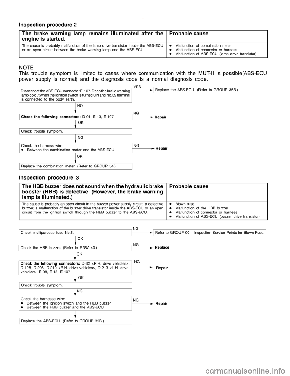
Inspection procedure 2
The brake warning lamp remains illuminated after the
engine is started.
Probable cause
The cause is probably malfunction of thelampdrive transistor inside the ABS-ECU
or an opencircuit between the brake warninglamp and theABS-ECU.DMalfunction of combination meter
DMalfunction of connector or harness
DMalfunction of ABS-ECU (lamp drive transistor)
NOTE
This trouble symptom is limited to cases where communication with the MUT-II is possible(ABS-ECU
power supply is normal) and the diagnosis code is a normal diagnosis code.
Repair NG
Repair
Replace the combination meter. (Refer to GROUP 54.)
OK
YESReplace the ABS-ECU. (Refer to GROUP 35B.)
NO
Disconnect the ABS-ECU connector E-107. Does the brake warning
lamp go outwhen the ignition switch is turned ON and No.39 terminal
is connected to the body earth.
OK
Check the following connectors:
D-01, E-13, E-107
Check trouble symptom.
Check the harness wire:
DBetween the combination meter and the ABS-ECUNG
NG
Inspection procedure 3
The HBB buzzer does not sound when the hydraulic brake
booster (HBB) is defective. (However, thebrake warning
lamp is illuminated.)
Probable cause
The cause is probably anopencircuit in the buzzer power supply circuit, a defective
buzzer, a malfunction of the buzzer drive transistor inside the ABS-ECU or anopen
circuit from the ignition switch through the HBB buzzer to the ABS-ECU.DBlown fuse
DMalfunction of the HBB buzzer
DMalfunction of connector or harness
DMalfunction of ABS-ECU (buzzer drive transistor)
Replace the ABS-ECU. (Refer to GROUP 35B.)
Repair NG
Repair
NG
OK
Check the HBB buzzer. (Refer to P.35A-40.)
OK
Check the following connectors:
D-32
D-128, D-208, D-210
NG
OK
Check trouble symptom.
Check multipurpose fuse No.5.NGRefer to GROUP 00 – Inspection Service Points for Blown Fuse.
Check the harnesse wire:
DBetween the ignition switch and the HBB buzzer
DBetween the HBB buzzer and the ABS-ECUNGReplace
www.WorkshopManuals.co.uk
Purchased from www.WorkshopManuals.co.uk
Page 1279 of 1839
ABS <4WD> -Troubleshooting35B-16
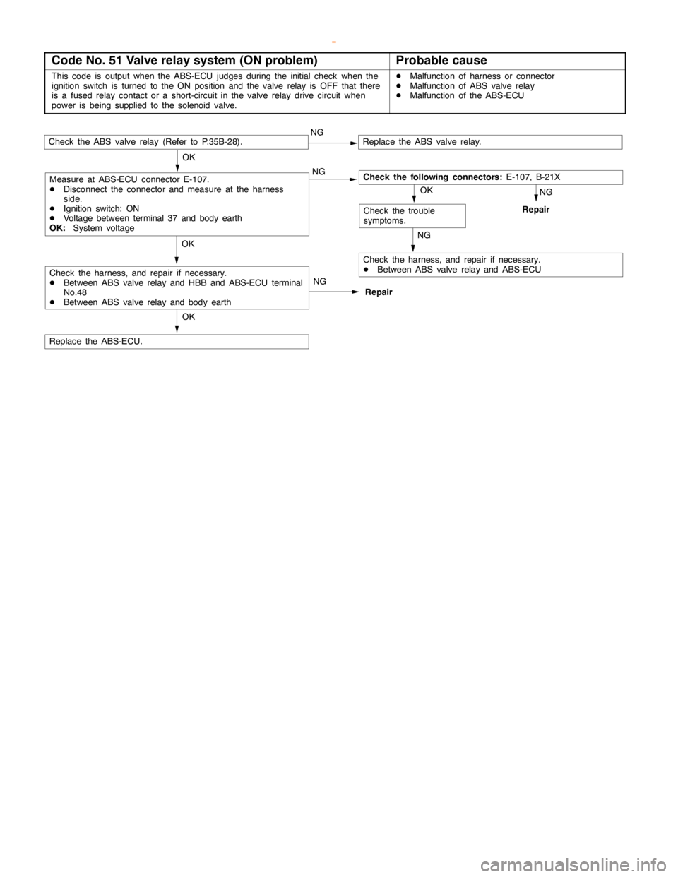
Code No. 51 Valve relay system (ON problem)Probable cause
This code is output when the ABS-ECU judges during the initial check when the
ignition switch is turned to the ON position and the valve relay is OFF that there
is a fused relay contact or a short-circuit in the valve relay drive circuit when
power isbeing supplied to the solenoidvalve.DMalfunction of harness or connector
DMalfunction of ABS valve relay
DMalfunction of the ABS-ECU
Repair NG
Check the ABS valve relay (Refer to P.35B-28).NGReplace the ABS valve relay.
OK
Check the harness, and repair if necessary.
DBetween ABS valve relay and ABS-ECU
OKNG
Repair
OK
Replace the ABS-ECU.
Check the trouble
symptoms.
Check the following connectors:E-107, B-21X OK
NG
NG
Check the harness, and repair if necessary.
DBetween ABS valve relay and HBB and ABS-ECU terminal
No.48
DBetween ABS valve relay and body earth
Measure at ABS-ECU connector E-107.
DDisconnect the connector and measure at the harness
side.
DIgnition switch: ON
DVoltage between terminal 37 and body earth
OK:System voltage
www.WorkshopManuals.co.uk
Purchased from www.WorkshopManuals.co.uk
Page 1282 of 1839
ABS <4WD> -Troubleshooting35B-19
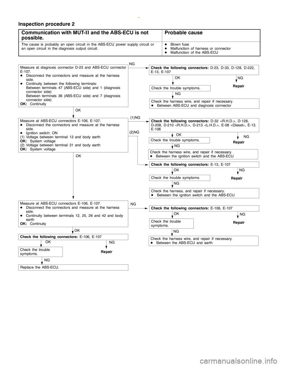
Inspection procedure 2
Communication with MUT-II
and the ABS-ECU is not
possible.
Probable cause
The cause is probably anopencircuit in the ABS-ECU power supply circuit or
an opencircuit in the diagnosis output circuit.DBlown fuse
DMalfunction of harness or connector
DMalfunction of the ABS-ECU
(1)NG
OK
Check the following connectors:E-13, E-107
NG
Repair
OK
Check the trouble symptoms.
NG
Check the harness wire, and repair if necessary.
DBetween ABS-ECU and diagnosis connector
OK
Check the following connectors:D-32
D-208, D-210
E-106
NG
Repair OKCheck the trouble symptoms.
NG
Check the harness wire, and repair if necessary.
DBetween the ignition switch and the ABS-ECU
NG
Repair
OK
Check the trouble symptoms.
NG
Check the harness, and repair if necessary.
DBetween the ignition switch and the ABS-ECU
OK
NG
Repair
OK
NG
Replace the ABS-ECU.
Measure at diagnosis connector D-23 and ABS-ECU connector
E-107.
DDisconnect the connectors and measure at the harness
side.
DContinuity between the following terminals:
Between terminals 47 (ABS-ECU side) and 1 (diagnosis
connector side)
Between terminals 36 (ABS-ECU side) and 7 (diagnosis
connector side)
OK:ContinuityNGCheck the following connectors:D-23, D-33, D-128, D-222,
E-13, E-107
Check the trouble
symptoms.
Check the following connectors:E-106, E-107(2)NG
Measure at ABS-ECU connectors E-106, E-107.
DDisconnect the connectors and measure at the harness
side.
DIgnition switch: ON
(1) Voltage between terminal 13 and body earth
OK:System voltage
(2) Voltage between terminal 31 and body earth
OK:System voltage
OK
Check the following connectors:E-106, E-107
Repair
OK
Check the trouble
symptoms.
NG
Check the harness wire, and repair if necessary.
DBetween the ABS-ECU and earthNG NG
Measure at ABS-ECU connectors E-106, E-107.
DDisconnect the connectors and measure at the harness
side.
DContinuity between terminals 12, 25, 26 and 42 and body
earth
OK:Continuity
www.WorkshopManuals.co.uk
Purchased from www.WorkshopManuals.co.uk
Page 1283 of 1839
ABS <4WD> -Troubleshooting35B-20
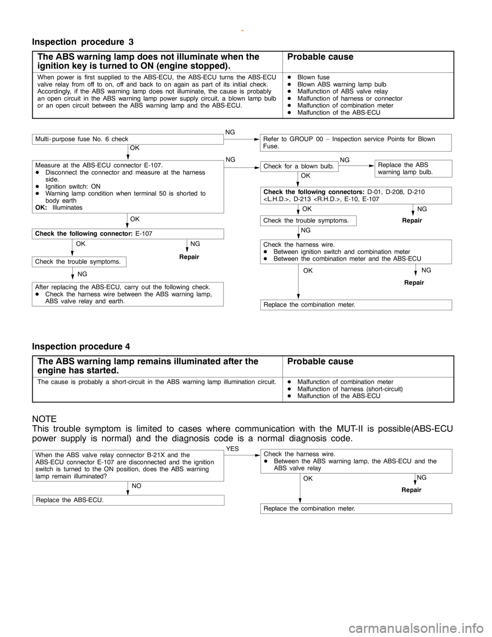
Inspection procedure 3
The ABS warning lamp does not illuminate when the
ignition key is turned to ON (engine stopped).
Probable cause
When power is first supplied to the ABS-ECU, the ABS-ECU turns the ABS-ECU
valve relay from off to on, off and back to onagain aspart of its initial check.
Accordingly, if the ABS warninglampdoes not illuminate, the cause is probably
an opencircuit in the ABS warninglamppower supply circuit, a blownlamp bulb
or an opencircuit between the ABS warninglamp and theABS-ECU.DBlown fuse
DBlown ABS warninglamp bulb
DMalfunction of ABS valve relay
DMalfunction of harness or connector
DMalfunction of combination meter
DMalfunction of the ABS-ECU
NG
Replace the combination meter.
NG
Repair
OK
NG
Check for a blown bulb.Replace the ABS
warning lamp bulb.
OK
NG
Repair
OK
Check the trouble symptoms.
Multi - purpose fuse No. 6 checkNGRefer to GROUP 00 – Inspection service Points for Blown
Fuse.
NG
Check the harness wire.
DBetween ignition switch and combination meter
DBetween the combination meter and the ABS-ECU
OK
OK
After replacing the ABS-ECU, carry out the following check.
DCheck the harness wire between the ABS warning lamp,
ABS valve relay and earth.
Check the following connector:E-107
NG
RepairCheck the trouble symptoms.OK
NG
Check the following connectors:D-01, D-208, D-210
Measure at the ABS-ECU connector E-107.
DDisconnect the connector and measure at the harness
side.
DIgnition switch: ON
DWarning lamp conditionwhen terminal 50 is shorted to
body earth
OK:Illuminates
Inspection procedure 4
The ABS warning lamp remains illuminated after the
engine has started.
Probable cause
The cause is probably a short-circuit in the ABS warninglamp illuminationcircuit.DMalfunction of combination meter
DMalfunction of harness (short-circuit)
DMalfunction of the ABS-ECU
NOTE
This trouble symptom is limited to cases where communication with the MUT-II is possible(ABS-ECU
power supply is normal) and the diagnosis code is a normal diagnosis code.
When the ABS valve relay connector B-21X and the
ABS-ECU connector E-107 are disconnected and the ignition
switch is turned to the ON position, does the ABS warning
lamp remain illuminated?YES
NO
Replace the ABS-ECU.
Replace the combination meter.
NG
Repair
OK
Check the harness wire.
DBetween the ABS warning lamp, the ABS-ECU and the
ABS valve relay
www.WorkshopManuals.co.uk
Purchased from www.WorkshopManuals.co.uk
Page 1513 of 1839
SRS -Troubleshooting52B-13
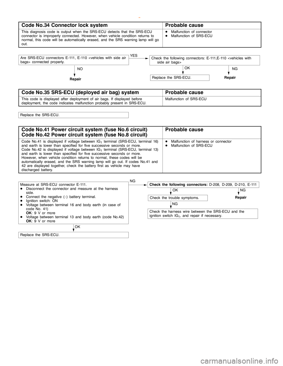
Code No.34 Connector lock systemProbable cause
This diagnosis code is output when the SRS-ECU detects that the SRS-ECU
connector is improperly connected. However, when vehicle condition returns to
normal, this code will be automatically erased, and the SRS warninglampwill go
out.DMalfunction of connector
DMalfunction of SRS-ECU
NG YES
Are SRS-ECU connectors E-111, E-110
Repair
Replace the SRS-ECU.
RepairNOOK
Code No.35 SRS-ECU (deployed air bag) systemProbable cause
This code is displayed after deployment of air bags. If displayed before
deployment, the code indicates malfunction probably present in SRS-ECU.Malfunction of SRS-ECU
Replace the SRS-ECU.
Code No.41 Power circuit system (fuse No.6 circuit)
Code No.42 Power circuit system (fuse No.8 circuit)Probable cause
Code No.41 is displayed if voltage between IG1terminal (SRS-ECU, terminal 16)
and earth is lower than specified for fivesuccessive seconds ormore.
Code No.42 is displayed if voltage between IG
1terminal (SRS-ECU, terminal 13)
and earth is lower than specified for fivesuccessive seconds ormore.
However, when vehicle condition returns to normal, these codes will be
automatically erased, and the SRS warning lampwill go out. If codes No.41 and
42 are displayed together, check the battery first as vehicle may have
discharged battery.
DMalfunction of harness or connector
DMalfunction of SRS-ECU
NGOK
NG NG
OK
Replace the SRS-ECU.
Measure at SRS-ECU connector E-111.
DDisconnect the connector and measure at the harness
side.
DConnect the negative ( - ) battery terminal.
DIgnition switch: ON
DVoltage between terminal 16 and body earth (in case of
code No. 41)
OK: 9 V or more
DVoltage between terminal 13 and body earth (code No.42)
OK: 9 V or moreCheck the following connectors:D-208, D-209, D-210, E-111
Check the trouble symptoms.Repair
Check the harness wire between the SRS-ECU and the
ignition switch IG
1, and repair if necessary.
www.WorkshopManuals.co.uk
Purchased from www.WorkshopManuals.co.uk
Page 1599 of 1839
CHASSIS ELECTRICAL-Combination Meter54A-29
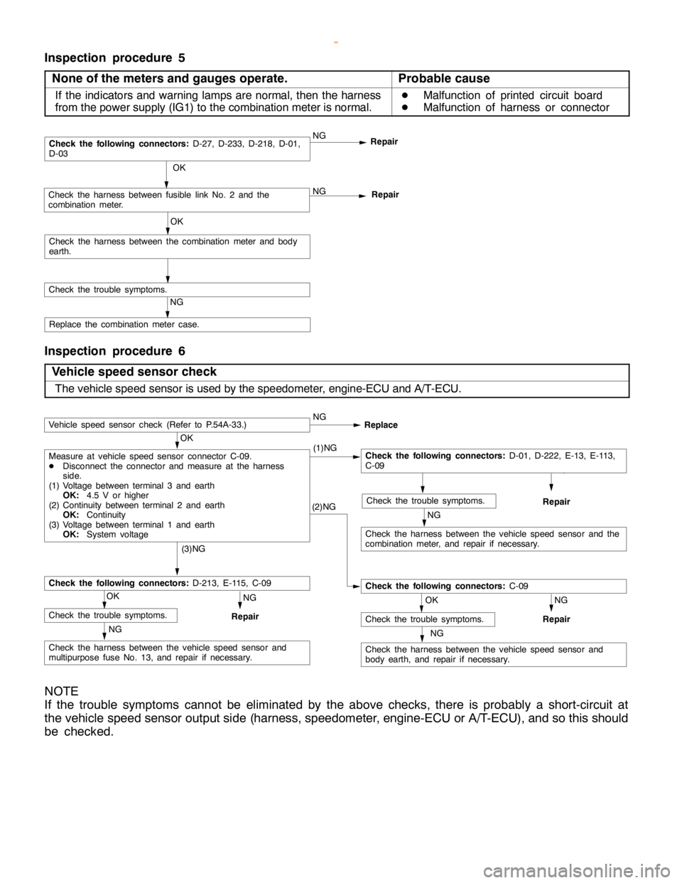
Inspection procedure 5
None of the meters and gauges operate.
Probable cause
If the indicators and warning lamps are normal, then the harness
from the power supply (IG1) to the combination meter is normal.D
Malfunction of printed circuit board
D
Malfunction of harness or connector
NGRepair NG
OK
Check the trouble symptoms.Repair
OK
Check the harness between the combination meter and body
earth.
Check the following connectors:D-27, D-233, D-218, D-01,
D-03
NG
Check the harness between fusible link No. 2 and the
combination meter.
Replace the combination meter case.
Inspection procedure 6
Vehicle speed sensor check
The vehicle speed sensor is used by the speedometer, engine-ECU and A/T-ECU.
NG
Check the harness between the vehicle speed sensor and
body earth, and repair if necessary.
RepairNG
OK
Check the trouble symptoms.NG
Check the harness between the vehicle speed sensor and
multipurpose fuse No. 13, and repair if necessary.
RepairNG
OK
Check the trouble symptoms.
Check the following connectors:D-213, E-115, C-09
(3)NG
(2)NG
Check the following connectors:C-09
NG
Check the harness between the vehicle speed sensor and the
combination meter, and repair if necessary.
RepairNG
OK
Check the trouble symptoms.
OK
Measure at vehicle speed sensor connector C-09.
DDisconnect the connector and measure at the harness
side.
(1) Voltage between terminal 3 and earth
OK:4.5 V or higher
(2) Continuity between terminal 2 and earth
OK:Continuity
(3) Voltage between terminal 1 and earth
OK:System voltage(1)NGCheck the following connectors:D-01, D-222, E-13, E-113,
C-09
Vehicle speed sensor check (Refer to P.54A-33.)NG
Replace
NOTE
If the trouble symptoms cannot be eliminated by the above checks, there is probably a short-circuit at
the vehicle speed sensor output side (harness, speedometer, engine-ECU or A/T-ECU), and so this should
be checked.
www.WorkshopManuals.co.uk
Purchased from www.WorkshopManuals.co.uk
Page 1630 of 1839

CHASSIS ELECTRICAL -Clock or Center Display54A-60
Terminal
No.Input/
OutputSignal symbolTerminal
voltage (V)Wiring harness
problemTrouble symptom caused by wiring
harness problem
Open
circuitShort
circuit
15Input/
OutputKHi: System
voltage
Lo: 0-1ExistsExistsValues on trip information screen (average
vehicle speed, fuel consumption and
cruising distance) are abnormal. Commu-
nication is impossible between the
engine-ECU and the MUT-II.
16------
17Input/
OutputM-BUSY
(AUDIO)Hi: 4-5
Lo: 0-1ExistsExistsAudio display does not appear. Panel
switch cannot be operated for audio unit.
Nighttime illumination does not appear for
audio unit.
18-SHIELD-GND----
19Input/
OutputM-BUSY
(A/C)Hi: 4-5
Lo: 0-1ExistsExistsA/C display does not appear.
Outside air temperature does not appear
20-SHIELD-GND----
21, 22------
23InputEX-TEMPExistsExistsOutside air temperature does not appear.
24InputILL+Hi: System
voltageExists-Nighttime illumination does not appear for
audio units.
Lo: 0-1
-ExistsBlown multipurpose fuse.
25InputACC (ACCSystem volt-Exists-Screen display does not appear.
power supply)age
-ExistsBlown multipurpose fuse.
26Input+BSystem volt-Exists-Screen display does not appear.
age
-ExistsBlown multipurpose fuse.
27InputVSSHi: System
voltage
Lo: 0-1ExistsExistsAbnormal outside air temperature ap-
pears.
(only diesel-powered vehicles)
28-GND (earth)-Exists-Screen display does not appear.
29, 30------
31-GND-TEMPExistsExistsOutside air temperature does not appear.
32InputILL -ExistsExistsThe display screen can not be dimmed.
33InputFUEL GAUGE-ExistsAbnormal cruising distance appears.
34, 35------
36InputIG1Hi: System
voltageExists-Communication with engine-ECU is im-
possible. Abnormal driving data values
appear.
-ExistsCommunication with engine-ECU is im-
possible. Abnormal driving data values
appear. Blown multipurpose fuse.
www.WorkshopManuals.co.uk
Purchased from www.WorkshopManuals.co.uk
Page 1632 of 1839
CHASSIS ELECTRICAL -Clock or Center Display54A-62
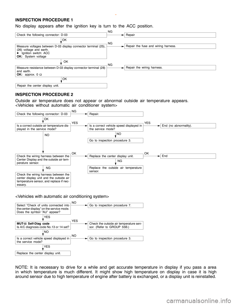
INSPECTION PROCEDURE 1
No display appears after the ignition key is turn to the ACC position.
OK
Measure voltages between D-03 display connector terminal (25),
(26) voltage and earth.
DIgnition switch: ACC
OK:System voltageNGRepair the fuse and wiring harness.
OK
Measure resistance between D-03 display connector terminal (28)
and earth.
OK:approx. 0
WNGRepair the wiring harness.
OK
Repair the center display unit.
Check the following connector: D-03NGRepair
INSPECTION PROCEDURE 2
Outside air temperature does not appear or abnormal outside air temperature appears.
Check the following connector: D-03NGRepair.
NO
Go to inspection procedure 3.
Check the wiring harness between the
Center Display and the outside air tem-
perature sensor.OKReplace the center display unit.OKEnd
NG
Replace the outside air temperature
sensor.NG
Check the wiring harness between the
center display unit and the outside air
temperature sensor, and replace if nec-
essary.
OK
Is a correct outside air temperature dis-
played in the servicemode?YESIs a correct vehicle speed displayed in
the servicemode?YESEnd (no abnormality).
NO
Select “Check of units connected into
the center display” on the service mode.
Does the symbol “AU” appear?NOGo to inspection procedure 7.
YES
Replace the center display unit.
YES
MUT-
IISelf-Diag code
Is A/C diagnosis code No.13 or 14 set?YESCheck the outside air temperature sen-
sor. (Refer to GROUP 55B.)
NO
Is a correct vehicle speed displayed in
the servicemode?NOGo to inspection procedure 3.
NOTE: It is necessary to drive for a while and get accurate temperature in display if you pass a area
in which temperature is much different. It might show high temperature on display in case it is high
around sensor due to high temperature of engine after battery is exchanged, or a display unit is reinstalled.
www.WorkshopManuals.co.uk
Purchased from www.WorkshopManuals.co.uk