2000 MITSUBISHI MONTERO compression ratio
[x] Cancel search: compression ratioPage 269 of 1839

GDI -Troubleshooting
Code No.P0301 No.1 cylinder misfire detected.
Code No.P0302 No.2 cylinder misfire detected.
Code No.P0303 No.3 cylinder misfire detected.
Code No.P0304 No.4 cylinder misfire detected.
Code No.P0305 No.5 cylinder misfire detected.Probable cause
Range of Check
DThe enginespeed is 500 - 4,500 r/min.
DWhile the engine is runningexcept deceleration and sudden acceleration.
Set Conditions
DThe number of misfires exceeds a predetermined number per 200engine
revolutions (Misfire has occurred in only one cylinder).
or
DThe number of misfires exceeds a predetermined number per 100engine
revolutions (Misfire has occurred in only one cylinder).DMalfunction of the ignition system
DAbnormal compression
DMalfunction of injector
DMalfunction of engine-ECU
NG
Check the harness wire between the
ignition coil and the engine-ECU.
NG
Replace
NG
Repair
(2) NG
OK
Check the ignition failure sensor
(Refer to GROUP 16 - Ignition
System.)
OK
Check the harness wire between the
ignition coil and the earth, and repair
if necessary. (3) NG
OK
Measure at ignition coil connectors
B-101, B-108, B-112, B-113, B-116,
B-119.
DDisconnect the connector and
measure at the harness side.
(1) The voltage between terminal 1
and earth
(Ignition switch: ON)
OK:
System voltage
(2) The voltage between terminal 3
and earth
(Engine: cranking)
OK:
0.5 - 4.0 V
(3) The resistance between terminal
2 and earth
OK:
2Wor less(1) NGCheck the following connectors:
B-04, B-107, D-208, D-223NG
Repair
Check the ignition coil (Refer to
GROUP 16 - Ignition System.)
Check the compression pressure.
(Refer to GROUP 11A - On-vehicle
Service.)Repair
Replace the engine-ECU.
OK
Check the harness wire between the
ignition coil and the ignition failure
sensor, and between the ignition coil
and the ignition failure sensor.
NG
Repair
OK
NGNG
Repair
OKReplace
NG
Check the spark plugs.
Check the trouble symptoms.
OK
Check the trouble symptoms.NGReplace the engine-ECU.
Check the following connectors:
B-101, B-108, B-112, B-113, B-116,
B-119
Check the following connector:
B-107, D-116
OK
www.WorkshopManuals.co.uk
Purchased from www.WorkshopManuals.co.uk
Page 295 of 1839
GDI -Troubleshooting
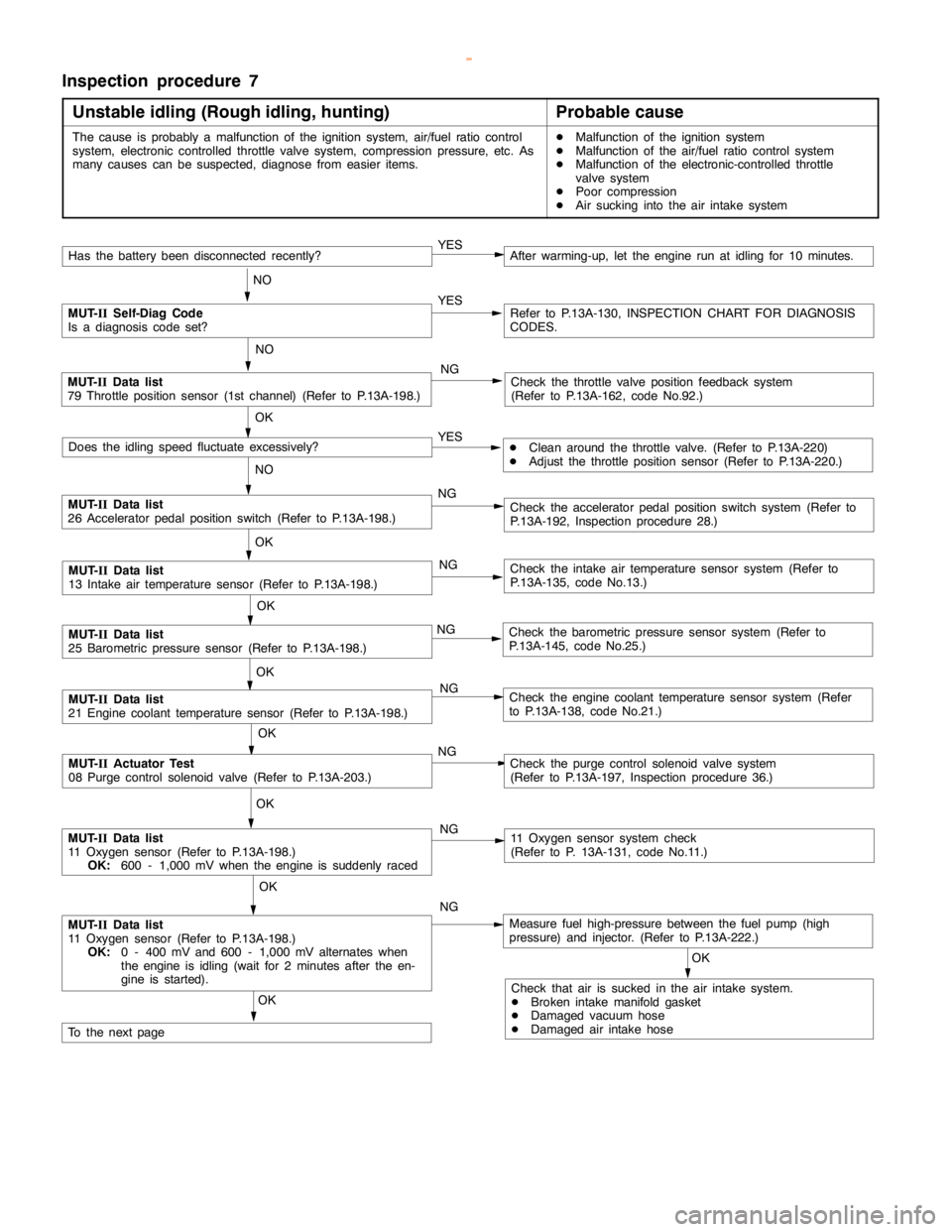
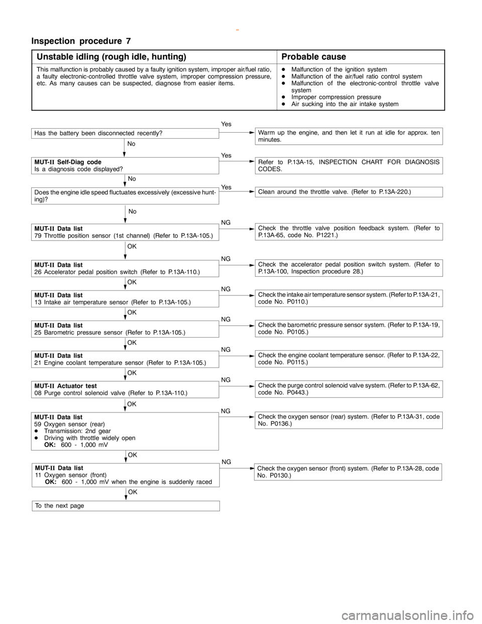
Inspection procedure 7
Unstable idling (rough idle, hunting)
Probable cause
This malfunction is probably caused by a faulty ignition system, improper air/fuel ratio,
a faulty electronic-controlled throttle valve system, improper compression pressure,
etc. As many causes can be suspected, diagnose from easier items.DMalfunction of the ignition system
DMalfunction of the air/fuel ratio control system
DMalfunction of the electronic-control throttle valve
system
DImproper compression pressure
DAir sucking into the air intake system
Has the batterybeen disconnectedrecently?Ye sWarm up the engine, and then let it run at idle for approx. ten
minutes.
No
MUT-
IISelf-Diag code
Is a diagnosis code displayed?Ye sRefer to P.13A-15, INSPECTION CHART FOR DIAGNOSIS
CODES.
No
Does theengine idlespeed fluctuates excessively (excessivehunt-
ing)?Ye sClean around the throttle valve. (Refer to P.13A-220.)
No
MUT-
IIData list
79 Throttle position sensor (1st channel) (Refer to P.13A-105.)NGCheck the throttle valve position feedback system. (Refer to
P.13A-65, code No. P1221.)
OK
MUT-
IIData list
26 Acceleratorpedal positionswitch (Refer to P.13A-110.)NGCheck the acceleratorpedal positionswitch system. (Refer to
P.13A-100, Inspection procedure 28.)
OK
MUT-
IIData list
13 Intake air temperature sensor (Refer to P.13A-105.)NGCheck the intake air temperature sensor system. (Refer to P.13A-21,
code No. P0110.)
OK
MUT-
IIData list
25 Barometric pressure sensor (Refer to P.13A-105.)NGCheck the barometric pressure sensor system. (Refer to P.13A-19,
code No. P0105.)
OK
MUT-
IIData list
21 Engine coolant temperature sensor (Refer to P.13A-105.)NGCheck theengine coolant temperaturesensor. (Refer to P.13A-22,
code No. P0115.)
OK
MUT-
IIActuator test
08 Purge control solenoid valve (Refer to P.13A-110.)NGCheck the purge control solenoid valve system. (Refer to P.13A-62,
code No. P0443.)
OK
MUT-
IIData list
11 Oxygen sensor (front)
OK:
600 - 1,000 mV when theengine is suddenlyracedNGCheck the oxygen sensor (front) system. (Refer to P.13A-28, code
No. P0130.)
OK
MUT-
IIData list
59 Oxygen sensor (rear)
DTransmission: 2nd gear
DDriving with throttle widelyopen
OK:
600 - 1,000 mVNGCheck the oxygen sensor (rear) system. (Refer to P.13A-31, code
No. P0136.)
OK
To the nextpage
www.WorkshopManuals.co.uk
Purchased from www.WorkshopManuals.co.uk
Page 298 of 1839

GDI -Troubleshooting
Inspection procedure 9
When the engine is cold, it stalls at idling. (Die out)
Probable cause
The cause is probably an incorrect air/fuel ratio or poor intake airamountwhen the
engine iscold.DMalfunction of the electronic-control throttle valve
system
DMalfunction of the throttle body
Have the battery terminalsbeen disconnectedrecently?Ye sWarm up the engine, and then let it run at idle for approx. ten
minutes.
No
MUT-
IISelf-Diag code
Is a diagnosis code displayed?Ye s(Refer to P.13A-15, INSPECTION CHART FOR DIAGNOSIS
CODES.)
No
Is the engine idlingcorrect after theengine has been warmed up?Ye sRefer to “Unstableidling (rough idle, hunting).”(Refer to P.13A-81,
Inspection procedure 7.)
No
MUT-
IIData list
22 Crankanglesensor (Refer to P.13A-105.)
Checkidlingspeed when theengine iscold.NGCheck the throttle valve position feedback system. (Refer to
P.13A-65, code No. P1221.)
OK
MUT-
IIData list
26 Acceleratorpedal positionswitch (Refer to P.13A-105.)NGCheck the accelerator position switch. (Refer to P.13A-100, Inspec-
tion procedure 28.)
OK
MUT-
IIData list
21 Engine coolant temperature sensor (Refer to P.13A-105.)NGCheck theengine coolant temperaturesensor. (Refer to P.13A-22,
code No. P0115.)
OK
MUT-
IIData list
68 EGR valve (Refer to P.13A-105.)NGCheck the EGR valve system. (Refer to P.13A-60, code No. P0403.)
OK
Does theenginestall immediately after the acceleratorpedal is
released?Ye sClean around the throttle valve. (Refer to P.13A-220.)
No
Measure fuel highpressure between the fuelpump (highpressure)
and injector. (Refer to P.13A-224.)NG
Repair
OK
Check ignition timing. (Refer to GROUP 11A - Engine Adjustment.)NGCheck that the crankanglesensor andtiming beltcover are properly
installed.
OK
Check ignition coil spark for each cylinder.
(1) Remove the ignition coil.
(2) Install a new sparkplug to the removed ignitioncoil.
(3) Disconnect the injector intermediate connector.
Caution
Never touch the connector terminal as approx. 100 V is
applied to the injector, or you are seriously injured.
(4) Earth the sparkplug electrodesecurely.
(5) Check that the sparkplug igniteswhen theengine iscranked.NGReplace the ignition coil.
OK
Check all the following items:
DSpark plugs
DCompression pressure
DEngine oilviscosityNGCheck trouble symptom. OK
Replace the injector.
www.WorkshopManuals.co.uk
Purchased from www.WorkshopManuals.co.uk
Page 299 of 1839
GDI -Troubleshooting
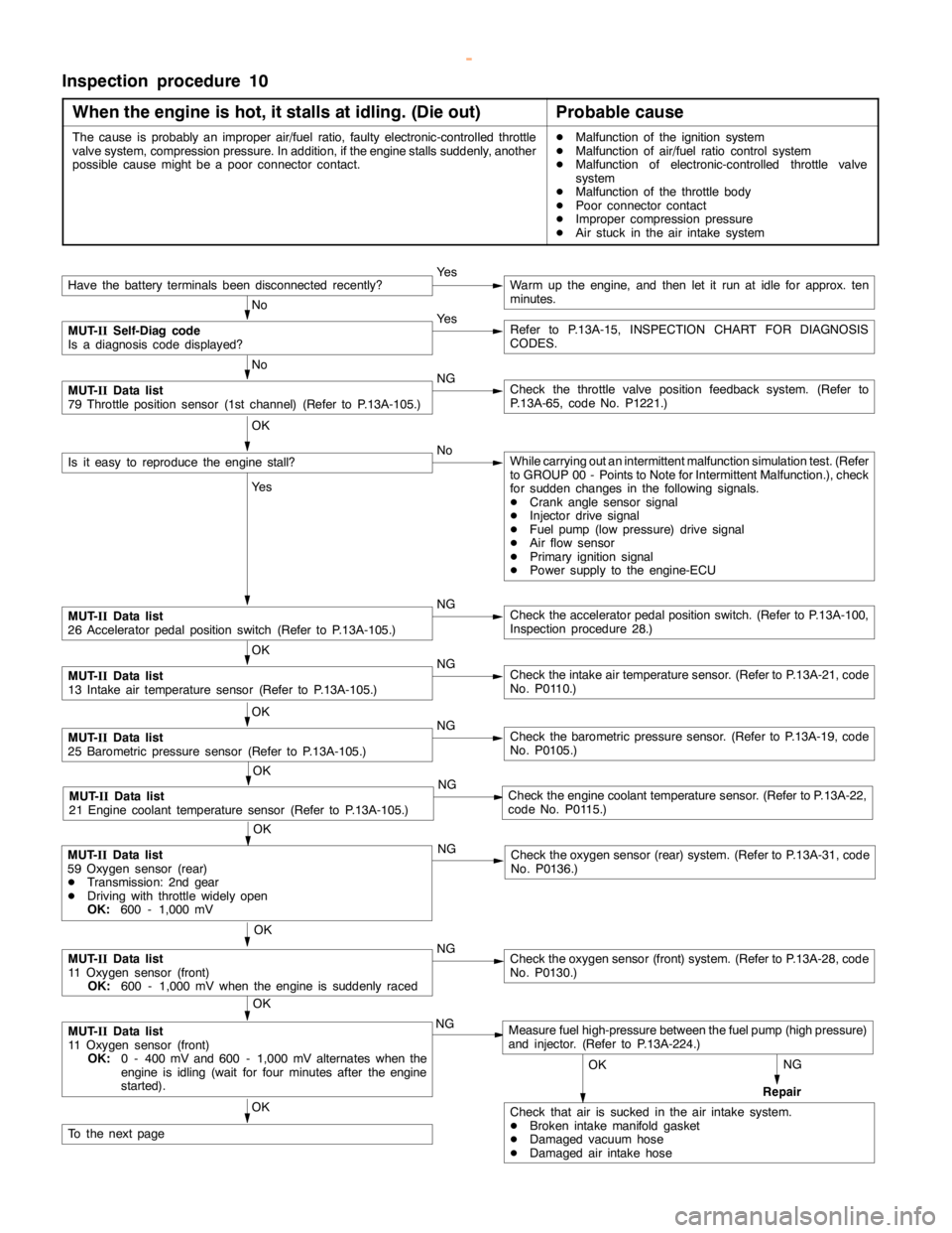
Inspection procedure 10
When the engine is hot, it stalls at idling. (Die out)
Probable cause
The cause is probably an improper air/fuel ratio, faulty electronic-controlled throttle
valve system, compression pressure. In addition, if theenginestalls suddenly, another
possible causemight be a poorconnector contact.DMalfunction of the ignition system
DMalfunction of air/fuel ratio control system
DMalfunction of electronic-controlled throttle valve
system
DMalfunction of the throttle body
DPoor connector contact
DImproper compression pressure
DAir stuck in the air intake system
NG
Repair
Have the battery terminalsbeen disconnectedrecently?Ye sWarm up the engine, and then let it run at idle for approx. ten
minutes.
No
MUT-
IISelf-Diag code
Is a diagnosis code displayed?Ye sRefer to P.13A-15, INSPECTION CHART FOR DIAGNOSIS
CODES.
No
MUT-
IIData list
79 Throttle position sensor (1st channel) (Refer to P.13A-105.)NGCheck the throttle valve position feedback system. (Refer to
P.13A-65, code No. P1221.)
OK
Is it easy to reproduce theengine stall?NoWhile carrying out an intermittent malfunction simulation test. (Refer
to GROUP 00 - Points to Note for Intermittent Malfunction.), check
for sudden changes in the following signals.
DCrankanglesensor signal
DInjector drive signal
DFuel pump(low pressure) drive signal
DAir flow sensor
DPrimary ignition signal
DPower supply to the engine-ECU
Ye s
MUT-
IIData list
26 Acceleratorpedal positionswitch (Refer to P.13A-105.)NGCheck the acceleratorpedal positionswitch. (Refer to P.13A-100,
Inspection procedure 28.)
OK
MUT-
IIData list
13 Intake air temperature sensor (Refer to P.13A-105.)NGCheck the intake air temperature sensor. (Refer to P.13A-21, code
No. P0110.)
OK
MUT-
IIData list
25 Barometric pressure sensor (Refer to P.13A-105.)NGCheck the barometric pressure sensor. (Refer to P.13A-19, code
No. P0105.)
OK
MUT-
IIData list
21 Engine coolant temperature sensor (Refer to P.13A-105.)NGCheck theengine coolant temperaturesensor. (Refer to P.13A-22,
code No. P0115.)
OK
MUT-
IIData list
11 Oxygen sensor (front)
OK:
600 - 1,000 mV when theengine is suddenlyracedNGCheck the oxygen sensor (front) system. (Refer to P.13A-28, code
No. P0130.)
OK
MUT-
IIData list
11 Oxygen sensor (front)
OK:
0 - 400 mV and 600 - 1,000 mV alternates when the
engine is idling(wait for four minutes after theengine
started).NGMeasure fuel high-pressure between the fuel pump (highpressure)
and injector. (Refer to P.13A-224.)
OK
Check that air is sucked in the air intake system.
DBroken intakemanifoldgasket
DDamaged vacuum hose
DDamaged air intake hoseOK
To the nextpage
OK
MUT-
IIData list
59 Oxygen sensor (rear)
DTransmission: 2nd gear
DDriving with throttle widelyopen
OK:
600 - 1,000 mVNGCheck the oxygen sensor (rear) system. (Refer to P.13A-31, code
No. P0136.)
www.WorkshopManuals.co.uk
Purchased from www.WorkshopManuals.co.uk
Page 303 of 1839
GDI -Troubleshooting
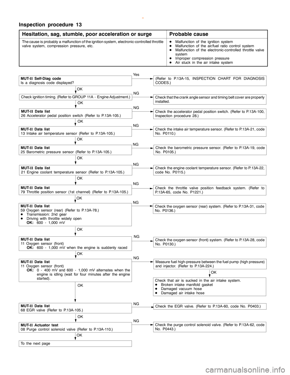
Inspection procedure 13
Hesitation, sag, stumble, poor acceleration or surge
Probable cause
The cause is probably a malfunction of the ignition system, electronic-controlled throttle
valve system, compression pressure, etc.DMalfunction of the ignition system
DMalfunction of the air/fuel ratio control system
DMalfunction of the electronic-controlled throttle valve
system
DImproper compression pressure
DAir stuck in the air intake system
MUT-
IISelf-Diag code
Is a diagnosis code displayed?Ye s(Refer to P.13A-15, INSPECTION CHART FOR DIAGNOSIS
CODES.)
OK
Check ignition timing. (Refer to GROUP 11A - Engine Adjustment.)NGCheck that the crankanglesensor andtiming beltcover are properly
installed.
OK
NG
Check the acceleratorpedal positionswitch. (Refer to P.13A-100,
Inspection procedure 28.)
OK
MUT-
IIData list
13 Intake air temperature sensor (Refer to P.13A-105.)NGCheck the intake air temperature sensor. (Refer to P.13A-21, code
No. P0110.)
OK
MUT-
IIData list
25 Barometric pressure sensor (Refer to P.13A-105.)NGCheck the barometric pressure sensor. (Refer to P.13A-19, code
No. P0105.)
OK
MUT-
IIData list
21 Engine coolant temperature sensor (Refer to P.13A-105.)NGCheck theengine coolant temperaturesensor. (Refer to P.13A-22,
code No. P0115.)
OK
MUT-
IIData list
79 Throttle position sensor (1st channel) (Refer to P.13A-105.)NGCheck the throttle valve position feedback system. (Refer to
P.13A-65, code No. P1221.)
OK
MUT-
IIData list
11 Oxygen sensor (front)
OK:
0 - 400 mV and 600 - 1,000 mV alternates when the
engine is idling(wait for four minutes after theengine
started).NGMeasure fuel high-pressure between the fuel pump (highpressure)
and injector. (Refer to P.13A-224.)
OK
MUT-
IIData list
11 Oxygen sensor (front)
OK:
600 - 1,000 mV when theengine is suddenlyracedNGCheck the oxygen sensor (front) system. (Refer to P.13A-28, code
No. P0130.)
OK
Check that air is sucked in the air intake system.
DBroken intake manifold gasket
DDamaged vacuum hose
DDamaged air intake hose
OK
MUT-
IIData list
68 EGR valve (Refer to P.13A-105.)NGCheck the EGR valve. (Refer to P.13A-60, code No. P0403.)
OK
MUT-
IIActuator test
08 Purge control solenoid valve (Refer to P.13A-110.)NGCheck the purge control solenoid valve. (Refer to P.13A-62, code
No. P0443.)
OK
To the nextpage
OK
MUT-
IIData list
59 Oxygen sensor (rear) (Refer to P.13A-78.)
DTransmission: 2nd gear
DDriving with throttle widelyopen
OK:
600 - 1,000 mVNGCheck the oxygen sensor (rear) system. (Refer to P.13A-31, code
No. P0136.)
MUT-
IIData list
26 Acceleratorpedal positionswitch (Refer to P.13A-105.)
www.WorkshopManuals.co.uk
Purchased from www.WorkshopManuals.co.uk
Page 304 of 1839
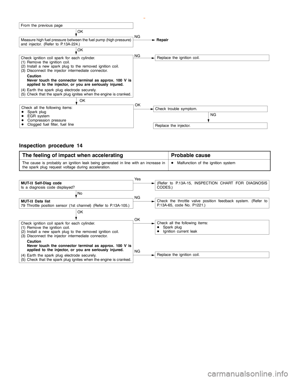
GDI -Troubleshooting
From the previouspage
OK
Measure high fuelpressure between the fuelpump (highpressure)
and injector. (Refer to P.13A-224.)NG
Repair
OK
Check ignition coil spark for each cylinder.
(1) Remove the ignition coil.
(2) Install a new sparkplug to the removed ignitioncoil.
(3) Disconnect the injector intermediate connector.
Caution
Never touch the connector terminal as approx. 100 V is
applied to the injector, or you are seriously injured.
(4) Earth the sparkplug electrodesecurely.
(5) Check that the sparkplug igniteswhen theengine iscranked.NGReplace the ignition coil.
OK
Check all the following items:
DSparkplug
DEGR system
DCompression pressure
DClogged fuel filter, fuel lineNGCheck trouble symptom.
Replace the injector.
OK
Inspection procedure 14
The feeling of impact when accelerating
Probable cause
The cause is probably an ignition leakbeing generated in linewith an increase in
the sparkplug request voltage during acceleration.DMalfunction of the ignition system
NGReplace the ignition coil.
MUT-
IISelf-Diag code
Is a diagnosis code displayed?Ye s(Refer to P.13A-15, INSPECTION CHART FOR DIAGNOSIS
CODES.)
No
MUT-
IIData list
79 Throttle position sensor (1st channel) (Refer to P.13A-105.)NGCheck the throttle valve position feedback system. (Refer to
P.13A-65, code No. P1221.)
OK
Check ignition coil spark for each cylinder.
(1) Remove the ignition coil.
(2) Install a new sparkplug to the removed ignitioncoil.
(3) Disconnect the injector intermediate connector.
Caution
Never touch the connector terminal as approx. 100 V is
applied to the injector, or you are seriously injured.
(4) Earth the sparkplug electrodesecurely.
(5) Check that the sparkplug igniteswhen theengine iscranked.OKCheck all the following items:
DSparkplug
DIgnition current leak
www.WorkshopManuals.co.uk
Purchased from www.WorkshopManuals.co.uk
Page 306 of 1839
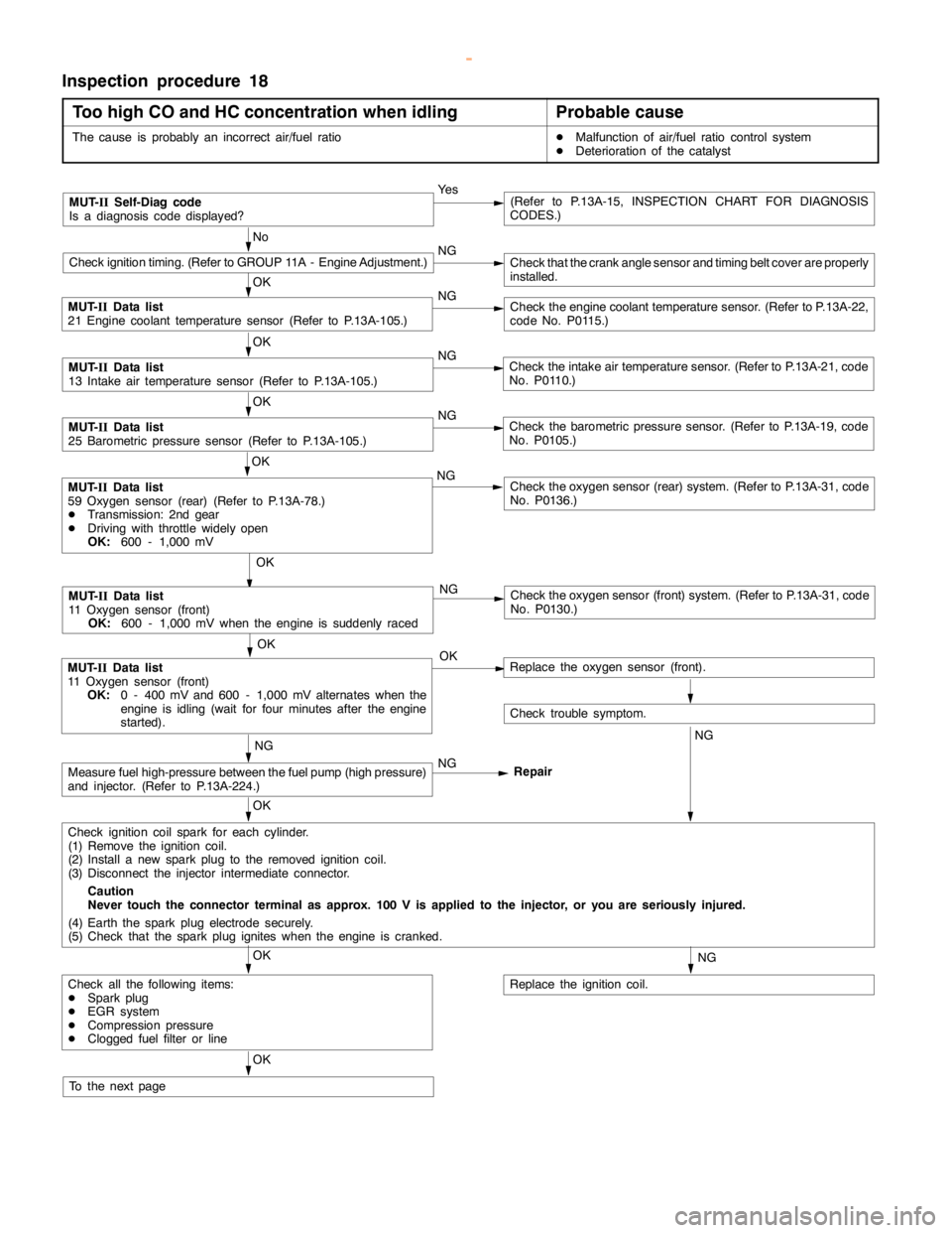
GDI -Troubleshooting
Inspection procedure 18
Too high CO and HC concentration when idling
Probable cause
The cause is probably an incorrect air/fuel ratioDMalfunction of air/fuel ratio control system
DDeterioration of the catalyst
MUT-
IISelf-Diag code
Is a diagnosis code displayed?Ye s(Refer to P.13A-15, INSPECTION CHART FOR DIAGNOSIS
CODES.)
No
Check ignition timing. (Refer to GROUP 11A - Engine Adjustment.)NGCheck that the crankanglesensor andtiming beltcover are properly
installed.
OK
MUT-
IIData list
21 Engine coolant temperature sensor (Refer to P.13A-105.)NGCheck theengine coolant temperaturesensor. (Refer to P.13A-22,
code No. P0115.)
OK
MUT-
IIData list
13 Intake air temperature sensor (Refer to P.13A-105.)NGCheck the intake air temperature sensor. (Refer to P.13A-21, code
No. P0110.)
OK
MUT-
IIData list
25 Barometric pressure sensor (Refer to P.13A-105.)NGCheck the barometric pressure sensor. (Refer to P.13A-19, code
No. P0105.)
OK
NG
Check the oxygen sensor (front) system. (Refer to P.13A-31, code
No. P0130.)
OK
MUT-
IIData list
11 Oxygen sensor (front)
OK:
0 - 400 mV and 600 - 1,000 mV alternates when the
engine is idling(wait for four minutes after theengine
started).OKReplace the oxygen sensor (front).
Check trouble symptom.
NGNG
Measure fuel high-pressure between the fuel pump (highpressure)
and injector. (Refer to P.13A-224.)NG
Repair
OK
Check ignition coil spark for each cylinder.
(1) Remove the ignition coil.
(2) Install a new sparkplug to the removed ignitioncoil.
(3) Disconnect the injector intermediate connector.
Caution
Never touch the connector terminal as approx. 100 V is applied to the injector, or you are seriously injured.
(4) Earth the sparkplug electrodesecurely.
(5) Check that the sparkplug igniteswhen theengine iscranked.
NG
Replace the ignition coil.
OK
Check all the following items:
DSparkplug
DEGR system
DCompression pressure
DClogged fuel filter or line
OK
To the nextpage
OK
MUT-
IIData list
59 Oxygen sensor (rear) (Refer to P.13A-78.)
DTransmission: 2nd gear
DDriving with throttle widelyopen
OK:
600 - 1,000 mVNGCheck the oxygen sensor (rear) system. (Refer to P.13A-31, code
No. P0136.)
MUT-
IIData list
11 Oxygen sensor (front)
OK:
600 - 1,000 mV when theengine is suddenlyraced
www.WorkshopManuals.co.uk
Purchased from www.WorkshopManuals.co.uk
Page 388 of 1839
