2000 MITSUBISHI MONTERO clock
[x] Cancel search: clockPage 821 of 1839

ENGINE AND EMISSION CONTROL -Auto-cruise Control System17-19
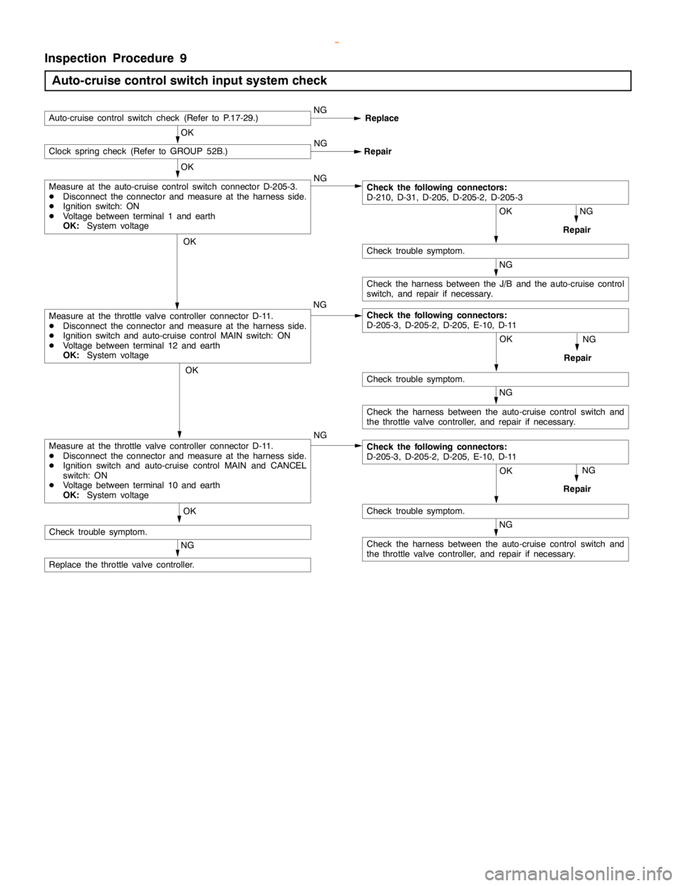
Inspection Procedure 9
Auto-cruise control switch input system check
NG
Check the harness between the auto-cruise control switch and
the throttle valve controller, and repair if necessary.
OK
NG
Repair
OK
Check trouble symptom. NG
OK
Auto-cruise control switch check (Refer to P.17-29.)NG
Replace
NG OKClock spring check (Refer to GROUP 52B.)
Repair
OK
NG
Repair
NG
OK
Check trouble symptom.
NG
Check the harness between the J/B and the auto-cruise control
switch, and repair if necessary.
Check the following connectors:
D-210, D-31, D-205, D-205-2, D-205-3
OK
Check trouble symptom.
NG
Repair
NG
Replace the throttle valve controller.NG
Measure at the throttle valve controller connector D-11.
DDisconnect the connector and measure at the harness side.
DIgnition switch and auto-cruise control MAIN switch: ON
DVoltage between terminal 12 and earth
OK:System voltage
Measure at the auto-cruise control switch connector D-205-3.
DDisconnect the connector and measure at the harness side.
DIgnition switch: ON
DVoltage between terminal 1 and earth
OK:System voltage
NG
Check the harness between the auto-cruise control switch and
the throttle valve controller, and repair if necessary.
OK
Check trouble symptom.
Check the following connectors:
D-205-3, D-205-2, D-205, E-10, D-11
Measure at the throttle valve controller connector D-11.
DDisconnect the connector and measure at the harness side.
DIgnition switch and auto-cruise control MAIN and CANCEL
switch: ON
DVoltage between terminal 10 and earth
OK:System voltageCheck the following connectors:
D-205-3, D-205-2, D-205, E-10, D-11
www.WorkshopManuals.co.uk
Purchased from www.WorkshopManuals.co.uk
Page 826 of 1839

ENGINE AND EMISSION CONTROL -Auto-cruise Control System17-24
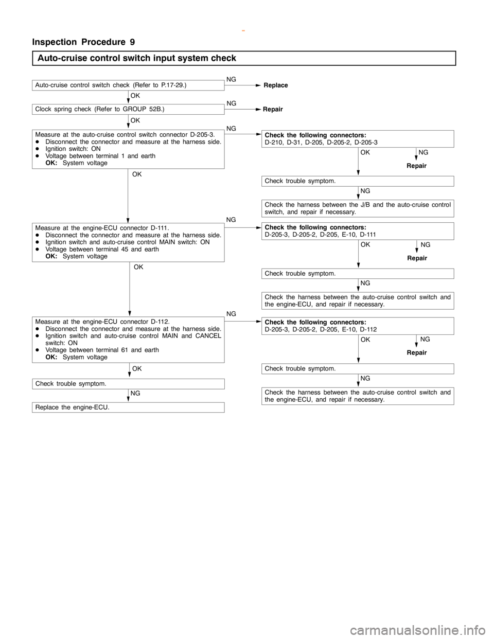
Inspection Procedure 9
Auto-cruise control switch input system check
NG
Check the harness between the auto-cruise control switch and
the engine-ECU, and repair if necessary.
OK
NG
Repair
OK
Check trouble symptom. NG
OK
Auto-cruise control switch check (Refer to P.17-29.)NG
Replace
NG OKClock spring check (Refer to GROUP 52B.)
Repair
OK
NG
Repair
NG
OK
Check trouble symptom.
NG
Check the harness between the J/B and the auto-cruise control
switch, and repair if necessary.
Check the following connectors:
D-210, D-31, D-205, D-205-2, D-205-3
OK
Check trouble symptom.
NG
Repair
NG
Replace the engine-ECU.NG
Measure at the engine-ECU connector D-111.
DDisconnect the connector and measure at the harness side.
DIgnition switch and auto-cruise control MAIN switch: ON
DVoltage between terminal 45 and earth
OK:System voltage
Measure at the auto-cruise control switch connector D-205-3.
DDisconnect the connector and measure at the harness side.
DIgnition switch: ON
DVoltage between terminal 1 and earth
OK:System voltage
NG
Check the harness between the auto-cruise control switch and
the engine-ECU, and repair if necessary.
OK
Check trouble symptom.
Check the following connectors:
D-205-3, D-205-2, D-205, E-10, D-111
Measure at the engine-ECU connector D-112.
DDisconnect the connector and measure at the harness side.
DIgnition switch and auto-cruise control MAIN and CANCEL
switch: ON
DVoltage between terminal 61 and earth
OK:System voltageCheck the following connectors:
D-205-3, D-205-2, D-205, E-10, D-112
www.WorkshopManuals.co.uk
Purchased from www.WorkshopManuals.co.uk
Page 902 of 1839

Page 1165 of 1839

POWER PLANT MOUNT - No.1 Crossmember32-7
No.1 CROSSMEMBER
REMOVAL AND INSTALLATION
Caution
1. Before removing the steering wheel and airbag module assembly, always refer to GROUP 52B
- Service Precautions, Airbag Module and Clock Spring. Also, set the front wheels so that
they are facing straight forward, and remove the ignition key. If you fail to do this, the SRS
clock spring will be damaged, causing the SRS airbag to be inoperative and serious injury.
2. *: Indicates parts which should be initially tightened, and then fully tightened after placing
the vehicle horizontally and loading the full weight of the engine on the vehicle body.
Pre-removal Operation
DUnder Cover Removal
DDrive Shaft Removal
(Refer to GROUP 26.)
DDifferential Carrier and No.2 Crossmember
Assembly Removal (Refer to GROUP 26 -
Freewheel Assembly and Differential Carrier.)
DUpper Arm Removal
(Refer to GROUP 33A.)
DLower Arm Removal
(Refer to GROUP 33A.)
DStabilizer Bar Removal
(Refer to GROUP 33A.)
DEngine Oil Cooler Removal<6G7>
(Refer to GROUP 12.)
DAir Cleaner Removal<4M4>
(Refer to GROUP 15.)
DIntercooler Removal<4M4>
(Refer to GROUP 15.)
DEngine Cover Removal
(Refer to GROUP 11A - Timing Belt.)
DRadiator Removal
(Refer to GROUP 14.)
DPower Steering Fluid Draining
(Refer to GROUP 37A - On - vehicle Service.)Post - installation Operations
DDifferential Carrier and No.2 Crossmember
Assembly Installation (Refer to GROUP 26 -
Freewheel Assembly and Differential Carrier.)
DDrive Shaft Installation
(Refer to GROUP 26.)
DLower Arm Installation
(Refer to GROUP 33A.)
DUpper Arm Installation
(Refer to GROUP 33A.)
DStabilizer Bar Installation
(Refer to GROUP 33A.)
DAir Cleaner Installation<4M4>
(Refer to GROUP 15.)
DIntercooler Installation<4M4>
(Refer to GROUP 15.)
DRadiator Installation
(Refer to GROUP 14.)
DEngine Oil Cooler Installation
(Refer to GROUP 12.)
DPower Steering Fluid Supplying
(Refer to GROUP 37A - On - vehicle Service.)
DPower Steering Fluid Line Bleeding
(Refer to GROUP 37A - On - vehicle Service.)
DPress the dust cover with a finger tocheck whether
the dust cover is cracked or damaged.
DChecking Steering Wheel Position with Wheels
StraightAhead
DFront Wheel AlignmentCheck and Adjustment
(Refer to GROUP 37A - On - vehicle Service.)
DUnder Cover Installation
DEngine Cover Installation
(Refer to GROUP 11A - Timing Belt.)
www.WorkshopManuals.co.uk
Purchased from www.WorkshopManuals.co.uk
Page 1310 of 1839

37A-1
STEERING
CONTENTS
GENERAL INFORMATION 2..................
SERVICE SPECIFICATIONS 5.................
LUBRICANTS 5..............................
SEALANT AND ADHESIVE 5.................
SPECIAL TOOLS 6..........................
ON-VEHICLE SERVICE 8.....................
Steering Wheel Free Play Check 8..............
Steering Angle Check 8........................
Tie Rod End Ball Joint Starting Torque Check 8..
Stationary Steering Effort Check 9...............
Steering Wheel Returnability Check 9............
Oil Pump Belt Tension Check <6G7,4D5> 9......Power Steering Fluid Level Check 10............
Power Steering Fluid Replacement 10...........
Power Steering System Bleeding 10.............
Oil Pump Pressure Test 11.....................
Power Steering Oil Pressure Switch Check
<6G7,4M4> 12.................................
Ball Joint Dust Cover Check 12.................
STEERING WHEEL AND SHAFT* 13.........
POWER STEERING GEAR BOX AND
LINKAGE 16................................
POWER STEERING OIL PUMP 30...........
POWER STEERING OIL HOSES 35..........
WARNINGS REGARDING SERVICING OF SUPPLEMENTAL RESTRAINT SYSTEM (SRS) EQUIPPED VEHICLES
WARNING!
(1) Improper service or maintenance of any component of the SRS, or any SRS-related component, can lead to personal
injury or death to service personnel (from inadvertent firing of the air bag) or to the driver and passenger (from rendering
the SRS inoperative).
(2) Service or maintenance of any SRS component or SRS-related component must be performed only at an authorized
MITSUBISHI dealer.
(3) MITSUBISHI dealer personnel must thoroughly review this manual, and especially its GROUP 52B - Supplemental
Restraint System (SRS) before beginning any service or maintenance of any component of the SRS or any SRS-related
component.
NOTE
The SRS includes the following components: SRS-ECU, SRS warning lamp, air bag module, clock spring and interconnecting
wiring. Other SRS-related components (that mayhave to be removed/installed in connectionwith SRS service or maintenance) are
indicated in the table of contents by an asterisk(*).
www.WorkshopManuals.co.uk
Purchased from www.WorkshopManuals.co.uk
Page 1457 of 1839

52A-2
INTERIOR
CONTENTS
SERVICE SPECIFICATIONS 3.................
SPECIAL TOOL 3............................
INSTRUMENT PANEL
INSTRUMENT PANEL
FLOOR CONSOLE 12........................
TRIMS 13...................................
SUNVISOR HOLDER 17......................FRONT SEAT 18............................
REAR/SECOND SEAT 25....................
THIRD SEAT 35.............................
FRONT SEAT BELT 38.......................
REAR SEAT BELT
SECOND/THIRD SEAT BELT
WARNINGS REGARDING SERVICING OF SUPPLEMENTAL RESTRAINT SYSTEM (SRS) EQUIPPED VEHICLES
WARNING!
(1) Improper service or maintenance of any component of the SRS, or any SRS-related component, can lead to personal
injury or death to service personnel (from inadvertent firing of the air bag) or to the driver (from rendering the SRS
inoperative).
(2) Service or maintenance of any SRS component or SRS-related component must be performed only at an authorized
MITSUBISHI dealer.
(3) MITSUBISHI dealer personnel must thoroughly review this manual, and especially its GROUP 52B - Supplemental
Restraint System (SRS) before beginning any service or maintenance of any component of the SRS or any SRS-related
component.
NOTE
The SRS includes the following components: front impact sensors, SRS-ECU, SRS warning lamp, air bag module, clock spring and
interconnecting wiring. Other SRS-related components (that mayhave to be removed/installed in connectionwith SRS service or
maintenance) are indicated in the table of contents by an asterisk(*).
www.WorkshopManuals.co.uk
Purchased from www.WorkshopManuals.co.uk
Page 1501 of 1839

52B-1
SUPPLEMENTAL
RESTRAINT
SYSTEM (SRS)
CONTENTS
GENERAL INFORMATION 2..................
SRS SERVICE PRECAUTIONS 3..............
SPECIAL TOOLS 5..........................
TEST EQUIPMENT 6.........................
TROUBLESHOOTING 7.......................
SRS MAINTENANCE 19.....................
POST-COLLISION DIAGNOSIS 23............
INDIVIDUAL COMPONENT SERVICE 26......
WARNING/CAUTION LABELS 27.............FRONT IMPACT SENSORS 28...............
SRS AIR BAG CONTROL UNIT
(SRS-ECU) 30...............................
AIR BAG MODULES AND CLOCK
SPRING 32.................................
SIDE IMPACT SENSOR 41..................
AIR BAG MODULE DISPOSAL
PROCEDURES 43...........................
Undeployed Air Bag Module Disposal 43.........
Deployed Air Bag Module Disposal
Procedures 52.................................
CAUTION
DCarefully read and observe the information in the SERVICE PRECAUTIONS (P.52B-3.) prior to any service.
DFor information concerning troubleshooting or maintenance, always observe the procedures in the Troubleshooting
(P.52B-7.) section.
DIf any SRS components are removed or replaced in connection with any service procedures, be sure to follow the
procedures in the INDIVIDUAL COMPONENT SERVICE section (P.52B-26.) for the components involved.
DIf you have any questions about theSRS, please contact your local distributor.
www.WorkshopManuals.co.uk
Purchased from www.WorkshopManuals.co.uk
Page 1510 of 1839

SRS -Troubleshooting52B-10
Code No.21, 22, 61, 62 Driver’s side air bag module (squib)
systemProbable cause
These diagnosis codes are output if there is an abnormal resistance between the
input terminals of the driver’s side air bagmodule(squib) inside the SRS-ECU.
The trouble causes for each diagnosis code No. are as follow.
However, as for code Nos.21 and 22, if the vehicle’s condition return to normal,
SRS warning lampwill go out. (Diagnosis code will remain stored)DMalfunction of clock spring
DPartially open asclock spring is not in neutral
position
DMalfunction of harness or connector
DMalfunction of driver’s air bagmodule(squib)
DMalfunction of SRS-ECU
Table 3
Code No.Trouble Symptom
21D
Short circuit in driver’s air bag module (squib) or harness short
D
Short circuit in clock spring
D
Poor connector contact*
22D
Open circuit in driver’s air bag module (squib) or open harness
D
Open circuit in clock spring
D
Disconnected driver’s air bag module (squib) connector
D
Partially open as clock spring is not in neutral position
D
Poor connector contact
61Short circuit in driver’s air bag module (squib) harness leading to the power supply
62Short circuit in driver’s air bag module (squib) harness leading to the earth
NOTE
*: The shorting bars, which short positive (+) and negative ( - ) wires to prevent the air bags from accidental
deployment during the disconnection of the connector, are set in the squib circuit connectors. In
a defective connector, the short-bar may be still working even after the connection of the connecter.
www.WorkshopManuals.co.uk
Purchased from www.WorkshopManuals.co.uk