Page 131 of 280

STARTING AND DRIVING
5–31
Power steering systemEC13A-Ah
When the engine is stopped, the power
steering system will not function and it will re-
quire greater manual effort to operate the
steering wheel. Keep this in mind in particu-
lar when towing the vehicle. Never turn off
the engine while driving.
Periodically check the power steering fluid
level.
CAUTION
Do not hold the steering wheel in the
fully turned position (either left or
right), for longer than 10 seconds.
This can cause damage to the power
steering pump due to reduced lu-
brication.
I08A027a
Inside rear-view mirrorEI08A-Be
The lever (A) at the bottom of the mirror can
be used to adjust the mirror to reduce the
glare from the headlamps of vehicles behind
you during night driving.
1-Normal
2-Anti-glare
WARNING
Do not attempt to adjust rear-view
mirrors while driving. This can be
dangerous.
Always adjust the mirrors before driv-
ing.
I08B091a
Outside rear-view mirrorEI08A-Za
On the driver’s seat side, a compound
curved-surface mirror is used, while on the
front passenger’s seat side, a single curved-
surface mirror is used.
The compound curved-surface mirror has
different curvatures between the inner and
outer sides of the boundary line (A).
The inner side of the boundary line provides
the same vision as that available from an
ordinary door mirror.
However, the outer side of the boundary line
provides a wider vision than an ordinary door
mirror.
Page 132 of 280
STARTING AND DRIVING
5–32
WARNING
The sense of distance that you get
from an object you see on the inner
side of the mirror boundary line
differs from the sense of distance that
you get from an object you see on the
outer side.
An object you see on the outer side of
the boundary line of the mirror will
look farther away than it actually is
(farther away than if you see in a nor-
mal flat mirror) as compared with an
object you see on the inner side.
I08B041a
Manual remote-controlled
outside rear-view mirrors*
EI08BAAb
Adjust the mirrors by operating the lever as
indicated by the arrows.
1-Left and right
2-Up and down
LHD
I08B040a
Electric remote–controlled
outside rear–view mirrors*
EI08BBRa
The outside rear–view mirrors can be oper-
ated when the ignition switch is in the “ON”
or “ACC” position.
Place the lever (A) to the same side as the
mirror whose adjustment is desired.
L– Left outside rear–view mirror adjust-
ment
R– Right outside rear–view mirror ad-
justment
Page 133 of 280
STARTING AND DRIVING
5–33
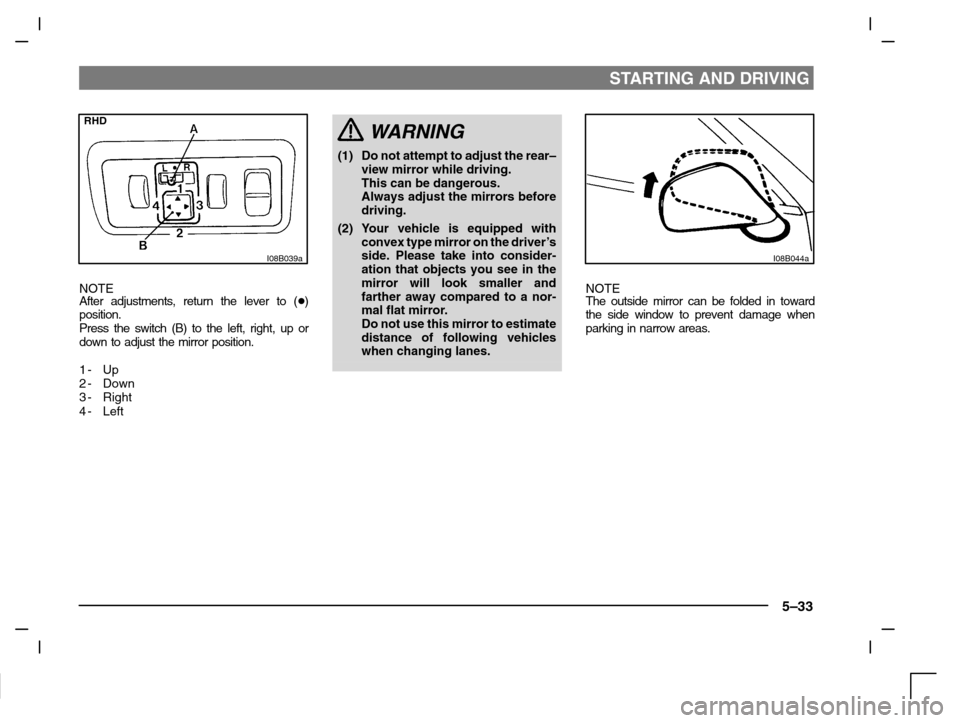
RHD
I08B039a
NOTE
After adjustments, return the lever to (�)
position.
Press the switch (B) to the left, right, up or
down to adjust the mirror position.
1- Up
2-Down
3-Right
4-Left
WARNING
(1) Do not attempt to adjust the rear–
view mirror while driving.
This can be dangerous.
Always adjust the mirrors before
driving.
(2) Your vehicle is equipped with
convex type mirror on the driver’s
side. Please take into consider-
ation that objects you see in the
mirror will look smaller and
farther away compared to a nor-
mal flat mirror.
Do not use this mirror to estimate
distance of following vehicles
when changing lanes.
I08B044a
NOTE
The outside mirror can be folded in toward
the side window to prevent damage when
parking in narrow areas.
Page 139 of 280
 Push the main switch at the end of the
lever. (Main switch OFF)
(2) Pull the a")
STARTING AND DRIVING
5–39
I10A123a
To deactivate
The auto–speed control can be deactivated
by the following ways.
(1) Push the main switch at the end of the
lever. (Main switch OFF)
(2) Pull the auto–speed control lever to-
ward you.
The auto–speed control can be deactivated
automatically in any of the following ways.
(3) By slightly tapping the brake pedal or
depressing it to reduce the speed.
(4) By depressing the clutch pedal (for mo-
dels with the manual transmission).
(5) By moving the selector lever to the “N”
(for models with the automatic trans-
mission).
(6) When, on a steep slope, etc., the ve-
hicle speed decreases to a speed which
is 15 km/h or more below the set speed.(7) When the vehicle speed decreases to
40 km/h or less.
WARNING
Although the auto–speed control can
be deactivated by moving the selec-
tor lever to the “N” position, never
move the selector lever to the “N”
position while driving.
A serious accident could occur; the
engine braking would be lost.
I10A124a
To resume set speed
If the vehicle speed remains 40 km/h or
higher when the auto–speed control is
deactivated by operating the auto–speed
control lever or by any one of the (2) to (7)
conditions noted above, the previously set
speed can be automatically resumed by pul-
ling up the auto–speed control lever.
Page 168 of 280
 When storing compact discs, always
store them in their individual cases.
Never place compact discs in direct
sunlight, or in any place where the tem-
perature or humidi")
FOR PLEASANT DRIVING
6–28
(4) When storing compact discs, always
store them in their individual cases.
Never place compact discs in direct
sunlight, or in any place where the tem-
perature or humidity is high.
H12F003a
(5) Take care never to touch the flat surface
of the disc where there is no label. Doing
so will contaminate the disc surface and
might adversely affect the sound quality.
When handling a compact disc, always
hold it by grasping the outer circumfer-
ence and the centre hole.
(6) To clean the disc, use a soft, clean, dry
cloth. Wipe directly from the centre hole
toward the outer-edge; do not wipe in a
circular pattern.
Never use any substances such as
benzine, paint thinner, a disc spray
cleaner, or an anti-static agent on the
disc.
(7) Do not use a disc that is cracked or
badly warped. Doing so might cause a
malfunction of the disc player.
(8) Do not use a ballpoint pen, felt pen, pen-
cil, etc. to write on the label surface of
the disc, and do not attach any other la-
bels, seals, etc.
CD player laser warning
Use of controls or adjustments, or
performance of procedures other than
normal use, may result in hazardous
radiation exposure.
Avoid direct exposure to beam.
Page 178 of 280

A- Outside air temperature display/Set
tempera")
FOR PLEASANT DRIVING
6–38
H14B106a
The following items are displayed in the multi
center display. (Refer to “Multi center display”
on page 4–24.)
A- Outside air temperature display/Set
temperature display
B-Blower speed indicator
C- Air flow indicatorNOTE
(1) The outside air temperature is usually
displayed in the position (A). The set
temperature is displayed for several
seconds while the temperature control
dial is operated.
(2) If the outside temperature drops below
about 3 �C, the alarm sounds and the
outside temperature figure flashes for
about 5 seconds. Turning the tempera-
ture adjustment dial during the period of
the alarm will have no effect on the dis-
play.
After completion of the warning, set the
temperature. (Refer to “Outside tem-
perature” on page 4–25.)
Operating the system as a manual
air conditioning
EH14CAF
If you operate the blower speed selection
dial or the mode selection dial as you de-
sired, the system is still automatically con-
trolled except selected function which dial is
operated. To return all operations to auto-
matic operation, set the dials to “AUT”
(AUTO) position.
H14D112a
Change of mode selectionEH14D-Y
The mode selection dial is operated accord-
ing to the need.
Turn the dial and the air outlet will be
changed.
Page 202 of 280

FOR EMERGENCIES
8–2
If the vehicle breaks downEN40B-Bc
If the vehicle breaks down on the road, move
it to the shoulder and use the hazard warning
flashers.
If the engine stops/fails
Vehicle operation and control are affected if
the engine stops. Before moving the vehicle
to a safe area be aware of the following:
1. The brake booster becomes inoperat-
ive and the pedal effort will increase.
Press down the brake pedal harder
than usual.
2. Since the power steering pump is no
longer operative, the steering wheel
feels heavy when turning it. Turn the
wheel with more effort than usual.
Operation under adverse
driving conditions
EI43ABAa
If your vehicle is stuck: in sand,
mud or snow
If the vehicle becomes stuck in snow, sand,
or mud, it can often be moved by a rocking
motion. Move the gearshift lever or selector
lever alternately between the 1st and Re-
verse position (with manual transmission),
the “L” (LOW) and “R” (REVERSE) position
(with INVECS–II 4A/T), and the Sport mode
and “R” (REVERSE) position (with INVECS–
II Sport Mode 4A/T) while applying slight
pressure to the accelerator pedal.
Avoid racing the engine or spinning the
wheels. Prolonged efforts to free a stuck ve-
hicle may result in overheating and trans-
mission failure. Allow the engine to idle for a
few minutes to let the transmission cool be-
tween rocking attempts.
If the vehicle remains stuck after several
rocking attempts, seek other assistance.
WARNING
When attempting to rock your vehicle
out of a stuck position, be sure that
the area around the vehicle is clear of
people and physical objects. The
rocking motion may cause the ve-
hicle to suddenly launch forward or
backward causing injury or damage
to nearby people or objects.
On a flooded road
(1) Avoid flooded roads. Water could enter
the brake discs, resulting in temporarily
ineffective brakes. In such cases, lightly
depress the brake pedal to see if the
brakes operate properly. If they do not,
lightly depress the pedal several times
while driving in order to dry the brake
pads.
(2) When driving in rain or on a road with
many puddles a layer of water may form
between the tyres and the road surface.
This reduces a tyre’s frictional resis-
tance on the road, resulting in loss of
steering stability and braking capability.
To cope with this, observe the following
items:
(a) Drive your vehicle at a slow speed.
(b) Do not drive on worn tyres. Always
maintain the specified tyre inflation
pressures.
Page 205 of 280
FOR EMERGENCIES
8–5
N22A181a
5. Place the jack under one of the jacking
points shown in the illustration. Use
the jacking point closest to the tyre to
be changed.
C- Jack–up point
WARNING
(1) Do not place the jack at any posi-
tion other than the one specified.
If the jack is placed at a wrong
position, the body of the vehicle
could be dented or the jack might
fall over and cause personal in-
jury.
(2) Avoid using the jack on a slope or
on a soft surface.
Otherwise the jack might tilt and
the vehicle falls down, causing an
unexpected accident. Always
use the jack on a flat, hard sur-
face. Before placing the jack,
check to ensure that there are no
sand or pebbles on the surface.N22A182a
6. Rotate the jack by hand until the
groove at the top of the jack fits in the
flange portion (D).

 Do n")