Page 513 of 1111

EM0D0±01
A00982
CO/HC Meter
± ENGINE MECHANICAL (2JZ±GE)CO/HC
EM±1
1355 Author�: Date�:
2000 LEXUS GS300/GS400 (RM718U)
CO/HC
INSPECTION
HINT:
This check is used only to determine whether or not the idle
CO/HC complies with regulations.
1. INITIAL CONDITIONS
(a) Engine at normal operating temperature
(b) Air cleaner installed
(c) All pipes and hoses of air induction system connected
(d) All accessories switched OFF
(e) All vacuum lines properly connected
(f) SFI system wiring connectors fully plugged
(g) Ignition timing checked correctly
(h) Transmission in neutral position
(i) Tachometer and CO/HC meter calibrated by hand
2. START ENGINE
3. RACE ENGINE AT 2,500 RPM FOR APPROX. 180
SECONDS
4. INSERT CO/HC METER TESTING PROBE AT LEAST
40 cm (1.3 ft) INTO TAILPIPE DURING IDLING
5. IMMEDIATELY CHECK CO/HC CONCENTRATION AT
IDLE AND/OR 2,500 RPM
HINT:
When doing the 2 mode (2,500 rpm and idle) test, follow the
measurement order prescribed by the applicable local regula-
tions.
Page 515 of 1111

B01982
LEXUS
Hand±Held
Tester
EM0D3±02
A02667
TC
E1 SST
DLC1
A02668
Igniter
White Lead Wire
A02637
EM±12
± ENGINE MECHANICAL (2JZ±GE)IGNITION TIMING
1366 Author�: Date�:
2000 LEXUS GS300/GS400 (RM718U)
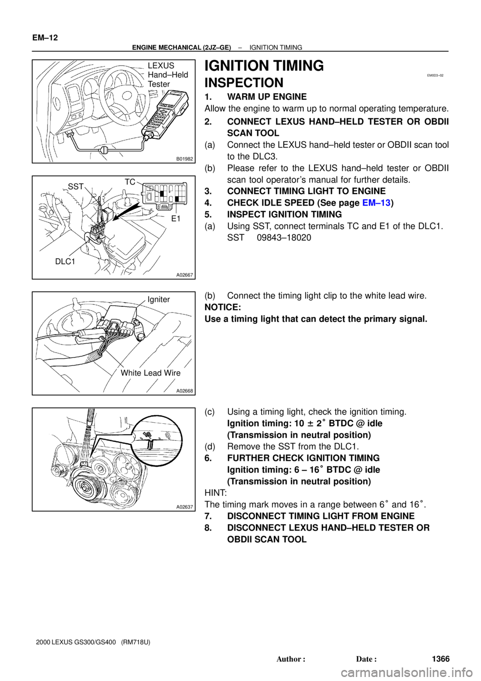
IGNITION TIMING
INSPECTION
1. WARM UP ENGINE
Allow the engine to warm up to normal operating temperature.
2. CONNECT LEXUS HAND±HELD TESTER OR OBDII
SCAN TOOL
(a) Connect the LEXUS hand±held tester or OBDII scan tool
to the DLC3.
(b) Please refer to the LEXUS hand±held tester or OBDII
scan tool operator's manual for further details.
3. CONNECT TIMING LIGHT TO ENGINE
4. CHECK IDLE SPEED (See page EM±13)
5. INSPECT IGNITION TIMING
(a) Using SST, connect terminals TC and E1 of the DLC1.
SST 09843±18020
(b) Connect the timing light clip to the white lead wire.
NOTICE:
Use a timing light that can detect the primary signal.
(c) Using a timing light, check the ignition timing.
Ignition timing: 10 ± 2° BTDC @ idle
(Transmission in neutral position)
(d) Remove the SST from the DLC1.
6. FURTHER CHECK IGNITION TIMING
Ignition timing: 6 ± 16° BTDC @ idle
(Transmission in neutral position)
HINT:
The timing mark moves in a range between 6° and 16°.
7. DISCONNECT TIMING LIGHT FROM ENGINE
8. DISCONNECT LEXUS HAND±HELD TESTER OR
OBDII SCAN TOOL
Page 516 of 1111
EM0D4±01
± ENGINE MECHANICAL (2JZ±GE)IDLE SPEED
EM±13
1367 Author�: Date�:
2000 LEXUS GS300/GS400 (RM718U)
IDLE SPEED
INSPECTION
1. INITIAL CONDITIONS
(a) Engine at normal operating temperature
(b) Air cleaner installed
(c) All pipes and hoses of air induction system connected
(d) All accessories switched OFF
(e) All vacuum lines properly connected
(f) SFI system wiring connectors fully plugged
(g) Ignition timing checked correctly
(h) Transmission in neutral position
2. CONNECT LEXUS HAND±HELD TESTER OR OBDII SCAN TOOL (See page EM±12)
3. INSPECT IDLE SPEED
(a) Race the engine speed at 2,500 rpm for approx. 90 seconds.
(b) Check the idle speed.
Idle speed: 700 ± 50 rpm
If the idle speed is not as specified, check the throttle body.
4. DISCONNECT LEXUS HAND±HELD TESTER OR OBDII SCAN TOOL
Page 569 of 1111

A02735
A09752
A11121
Case Clamp
New Clamp
A02819
± ENGINE MECHANICAL (2JZ±GE)CYLINDER HEAD
EM±57
1411 Author�: Date�:
2000 LEXUS GS300/GS400 (RM718U)
15. INSTALL VACUUM CONTROL VALVE SET AND NO.2
VACUUM PIPE
(a) Install the vacuum control valve set and No.2 vacuum
pipe with the 3 nuts.
Torque: 21 N´m (210 kgf´cm, 15 ft´lbf)
(b) Install the engine wire clamp to the clamp bracket of the
No.2 vacuum pipe.
(c) Connect the VSV connector for the ACIS.
16. INSTALL AIR INTAKE CHAMBER (See page SF±49)
17. INSTALL OIL DIPSTICK AND GUIDE FOR A/T
(See page EM±68)
18. INSTALL OIL DIPSTICK AND GUIDE FOR ENGINE
(See page LU±12)
19. INSTALL THROTTLE BODY AND INTAKE AIR
CONNECTOR ASSEMBLY (See page EM±5)
20. INSTALL WATER BYPASS OUTLET AND NO.1 WATER
BYPASS PIPE (See page CO±13)
21. INSTALL EXHAUST MANIFOLD
(a) Install 2 new gaskets to the cylinder head.
(b) Using a 14 mm deep socket wrench, install the exhaust
manifold with the 8 nuts. Uniformly tighten the nuts in sev-
eral passes.
Torque: 40 N´m (408 kgf´cm, 30 ft´lbf)
(c) Connect the 3 heated oxygen sensor connectors and
clamp.
(d) Install a new clamp and the case clamp as shown in the
illustration.
22. CONNECT FRONT EXHAUST PIPE TO EXHAUST
MANIFOLD
(a) Temporarily install the pipe support bracket to the trans-
mission with the 2 bolts.
(b) Install 2 new gaskets to front end of the front exhaust pipe,
and connect the front exhaust pipe to the exhaust man-
ifold with the 3 bolts and nuts.
Torque: 44 N´m (440 kgf´cm, 32 ft´lbf)
(c) Tighten the 2 bolts holding the pipe support bracket to the
transmission.
Page 572 of 1111
A09753
Transmission Control Rod
13 (130, 9)
13 (130, 9)
Rear Engine Mounting Member
Fuel Inlet
� Gasket
29 (300, 22)
13.5 (135, 10)25.5 (260, 19)
70 (714, 52)
Hole Plug PS Vane Pump Assembly
PS Pump Rear Stay57.9 (590, 43)
39.2 (400, 29)
65 (660, 48)
65 (660, 48)
35 (360, 26)
26 (265, 19)
52 (530, 38)
57.9 (590, 43)
A/C Compressor
52 (530, 38)
52 (530, 38)
Adjusting Washer
PS Gear Housing
Propeller Shaft
79 (805, 58)
37 (375, 27)
Heat Insulator
Heat Insulator
Adjusting Nut
69 (700, 51)
79 (805, 58)
44 (440, 32)
� Gasket� Gasket
Ring
Ring
Center Exhaust Pipe
Front Floor Center Brace
� Gasket
Front Exhaust Pipe
(with Rear TWC)
44 (440, 32)
� Gasket
45 (450, 32)
Heated Oxygen Sensor
(Bank 2 Sensor 2)
44 (440, 32)
N´m (kgf´cm, ft´lbf) : Specified torque
� Non±reusable part
44 (440, 32)Pipe Support
Bracket
Hose
EM±60
± ENGINE MECHANICAL (2JZ±GE)ENGINE UNIT
1414 Author�: Date�:
2000 LEXUS GS300/GS400 (RM718U)
Page 573 of 1111
A09754
� GasketEngine Wire
Clamp
Engine
StarterOil Dipstick and Guide for A/T
Starter Wire Hole Plug
N´m (kgf´cm, ft´lbf) : Specified torque
� Non±reusable part
40 (408, 30)
37 (380, 27)
x 8
� O±Ring
x 4 Pipe Clamp
PNP Switch Connector
Engine Wire
VSS Connector
Solenoid
Connector
Direct Clutch Speed
Sensor Connector
Oil Cooler Pipe for A/T
Exhaust Manifold
Transmission
(with Torque
Converter Clutch)
x 5
Ground Wire
72 (730, 53)
17 mm Bolt
�83 (850, 61)x 8
Rear Plate
Drive Plate
48 (490, 35)
x 6
Front Spacer
14 mm Bolt
37 (380, 27)
± ENGINE MECHANICAL (2JZ±GE)ENGINE UNIT
EM±61
1415 Author�: Date�:
2000 LEXUS GS300/GS400 (RM718U)
Page 576 of 1111

A02823
A01483
A02794
A02791
A02789
Matchmark
Wire Clamp
EM±64
± ENGINE MECHANICAL (2JZ±GE)ENGINE UNIT
1418 Author�: Date�:
2000 LEXUS GS300/GS400 (RM718U)
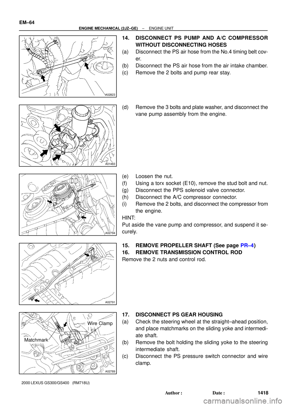
14. DISCONNECT PS PUMP AND A/C COMPRESSOR
WITHOUT DISCONNECTING HOSES
(a) Disconnect the PS air hose from the No.4 timing belt cov-
er.
(b) Disconnect the PS air hose from the air intake chamber.
(c) Remove the 2 bolts and pump rear stay.
(d) Remove the 3 bolts and plate washer, and disconnect the
vane pump assembly from the engine.
(e) Loosen the nut.
(f) Using a torx socket (E10), remove the stud bolt and nut.
(g) Disconnect the PPS solenoid valve connector.
(h) Disconnect the A/C compressor connector.
(i) Remove the 2 bolts, and disconnect the compressor from
the engine.
HINT:
Put aside the vane pump and compressor, and suspend it se-
curely.
15. REMOVE PROPELLER SHAFT (See page PR±4)
16. REMOVE TRANSMISSION CONTROL ROD
Remove the 2 nuts and control rod.
17. DISCONNECT PS GEAR HOUSING
(a) Check the steering wheel at the straight±ahead position,
and place matchmarks on the sliding yoke and intermedi-
ate shaft.
(b) Remove the bolt holding the sliding yoke to the steering
intermediate shaft.
(c) Disconnect the PS pressure switch connector and wire
clamp.
Page 577 of 1111
A02790
A02797
A02796
A02795
A02798
± ENGINE MECHANICAL (2JZ±GE)ENGINE UNIT
EM±65
1419 Author�: Date�:
2000 LEXUS GS300/GS400 (RM718U)
(d) Remove the 4 bolts, and disconnect the PS housing from
the front frame.
(e) Disconnect the sliding yoke from the intermediate shaft.
HINT:
Suspend the PS gear housing securely.
18. REMOVE ENGINE AND TRANSMISSION ASSEMBLY
FROM VEHICLE
(a) Install the No.1 engine hanger in the correct direction.
Part No.:
No.1 engine hanger 12281±46050
Bolt 90105±10345
Torque: 40 N´m (400 kgf´cm, 30 ft´lbf)
(b) Attach the engine chain hoist to the engine hangers.
(c) Remove the 2 hole plugs.
(d) Remove the 4 nuts holding the engine mounting insula-
tors to the front suspension crossmember.
(e) Remove the 4 bolts, 4 nuts and rear engine mounting
member.
(f) Lift the engine out of the vehicle slowly and carefully.
HINT:
Make sure the engine is clear of all wiring, hoses and cables.
(g) Place the engine and transmission assembly onto the
stand.