Page 1096 of 1111
R00040
SST
SA1130
SST
SST
R00587
SST
R00054
SST
± SUSPENSION AND AXLEREAR DIFFERENTIAL CARRIER
SA±81
2081 Author�: Date�:
2000 LEXUS GS300/GS400 (RM718U)
22. INSTALL OIL SEAL
(a) Apply MP grease to a new oil seal lip.
(b) Using SST, install the oil seal until its end is flush with the
surface of the differential carrier.
SST 09316±60011 (09316±00011, 09316±00041),
09502±12010
23. INSTALL COMPANION FLANGE
Using SST and a press, install the companion flange.
SST 09223±56010, 09325±40010
NOTICE:
Be careful not to damage the oil seal.
24. ADJUST DRIVE PINION PRELOAD
(a) Coat the threads and flange of a new nut with hypoid gear
oil for LSD.
(b) Using SST, tighten the nut.
SST 09229±55010, 09330±00021
(c) Using SST and a torque wrench, measure the preload.
SST 09229±55010
Preload (at starting):
New bearing:
1.5 ± 1.8 N´m (15 ± 18 kgf´cm, 13.0 ± 15.6 in.´lbf)
Reused bearing:
0.5 ± 0.8 N´m (5 ± 8 kgf´cm, 4.3 ± 6.9 in.´lbf)
Page 1097 of 1111

If the preload is greater than the specification, repl")
R00587
SST
R00032
R15856
SST
R00034
SA±82
± SUSPENSION AND AXLEREAR DIFFERENTIAL CARRIER
2082 Author�: Date�:
2000 LEXUS GS300/GS400 (RM718U)
If the preload is greater than the specification, replace the
spacer.
If the preload is less than the specification, retighten the nut with
a force of 13 N´m (130 kgf´cm, 9 ft´lbf) at a time until the speci-
fied preload is reached.
Torque: 490 N´m (5,000 kgf´cm, 362 ft´lbf) or less
If the maximum torque is exceeded while retightening the nut,
replace the spacer and repeat the preload procedure.
Do not back off the nut to reduce the preload.
25. CHECK RUNOUT OF DRIVE PINION SHAFT
(See page SA±67)
26. INSTALL DIFFERENTIAL CASE IN CARRIER
(See step 11)
27. INSTALL O±RING FROM DIFFERENTIAL CARRIER
RETAINERS
(a) Coat 2 new O±rings with hypoid gear oil.
(b) Install the 2 O±rings to the carrier retainers.
28. INSTALL OIL SEALS FROM DIFFERENTIAL CARRIER
RETAINERS
(a) Using SST and a press, install 2 new oil seals to the carrier
retainers.
SST 09608±32010, 09950±70010 (09950±07150)
(b) Coat the MP grease to the oil seal lip.
29. INSTALL DIFFERENTIAL CARRIER RETAINERS
30. RECHECK BACKLASH, TOTAL PRELOAD AND
TOOTH CONTACT PATTERN
31. STAKE DRIVE PINION NUT
32. INSTALL SNAP RINGS TO SIDE GEAR SHAFTS
(a) Install 2 new snap rings to the side gear shafts.
(b) Coat the MP grease to the snap rings.
Page 1098 of 1111
R00240
F02352
FIPG
± SUSPENSION AND AXLEREAR DIFFERENTIAL CARRIER
SA±83
2083 Author�: Date�:
2000 LEXUS GS300/GS400 (RM718U)
33. INSTALL SIDE GEAR SHAFTS
Using a brass and hammer, install the 2 side gear shafts.
HINT:
Whether or not the side gear shaft is making contact with the
pinion shaft can be known by the sound or feeling when driving
it in.
NOTICE:
Be careful not to damage the oil seal.
34. REMOVE DIFFERENTIAL CARRIER FROM OVER-
HAUL STAND, ETC.
35. INSTALL DIFFERENTIAL CARRIER COVER
(a) Clean the contact surfaces of the carrier and cover of any
residual FIPG material using cleaner.
(b) Coat FIPG to the carrier or cover.
FIPG:
Part No. 08826±00090, THREE BOND 1281 or equiva-
lent
(c) Install the carrier cover to the carrier with the 8 bolts.
Torque: 47 N´m (475 kgf´cm, 34 ft´lbf)
(d) Install the breather plug.
Torque: 21 N´m (210 kgf´cm, 15 ft´lbf)
Page 1101 of 1111
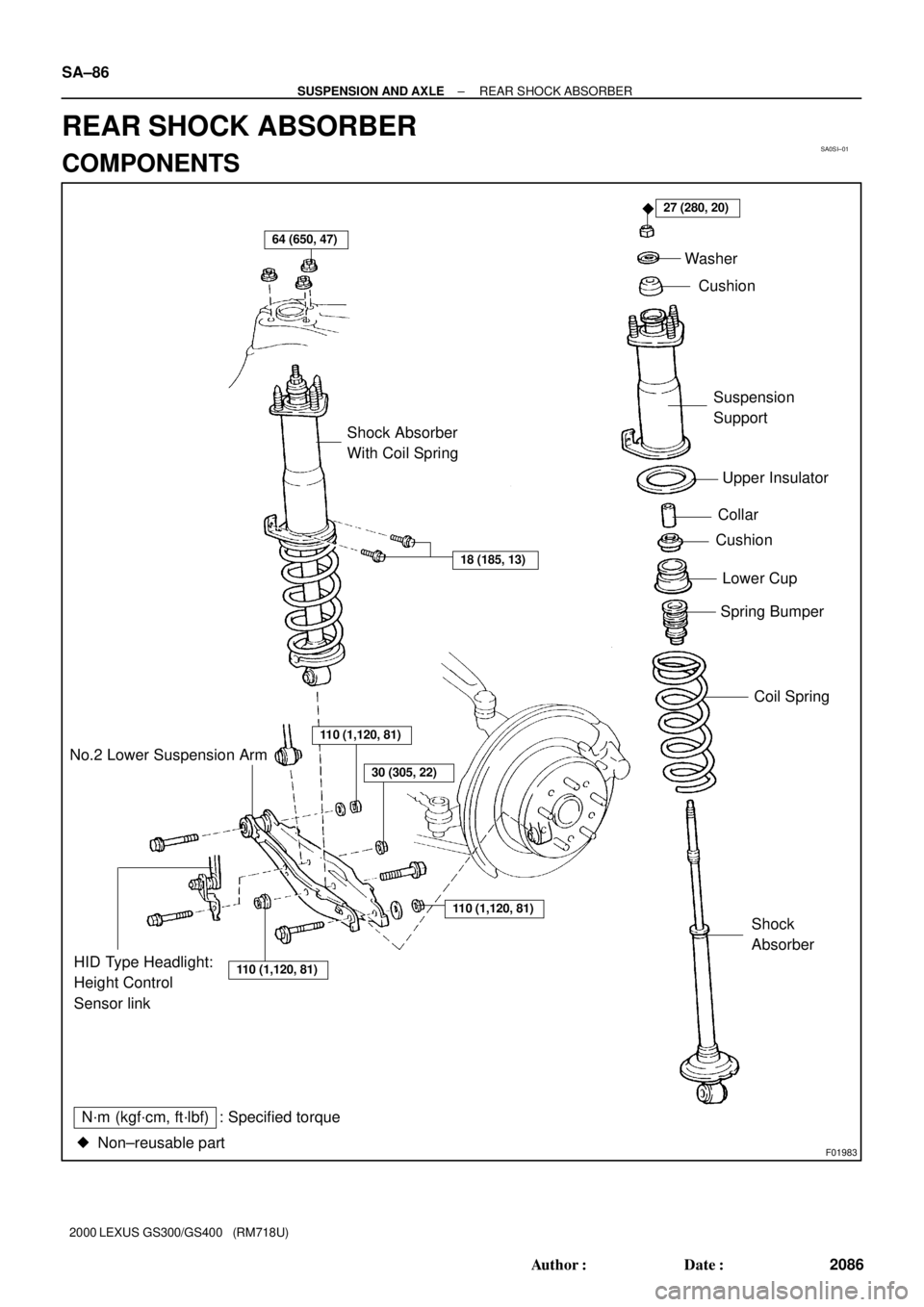
SA0SI±01
F01983
64 (650, 47)
27 (280, 20)
18 (185, 13)
�
Shock Absorber
With Coil SpringWasher
Cushion
Suspension
Support
Upper Insulator
Collar
Cushion
Spring Bumper
Coil Spring
110 (1,120, 81)
110 (1,120, 81)HID Type Headlight:
Height Control
Sensor linkShock
Absorber No.2 Lower Suspension Arm
N´m (kgf´cm, ft´lbf) : Specified torque
Non±reusable part �
110 (1,120, 81)
30 (305, 22)
Lower Cup
SA±86
± SUSPENSION AND AXLEREAR SHOCK ABSORBER
2086 Author�: Date�:
2000 LEXUS GS300/GS400 (RM718U)
REAR SHOCK ABSORBER
COMPONENTS
Page 1102 of 1111
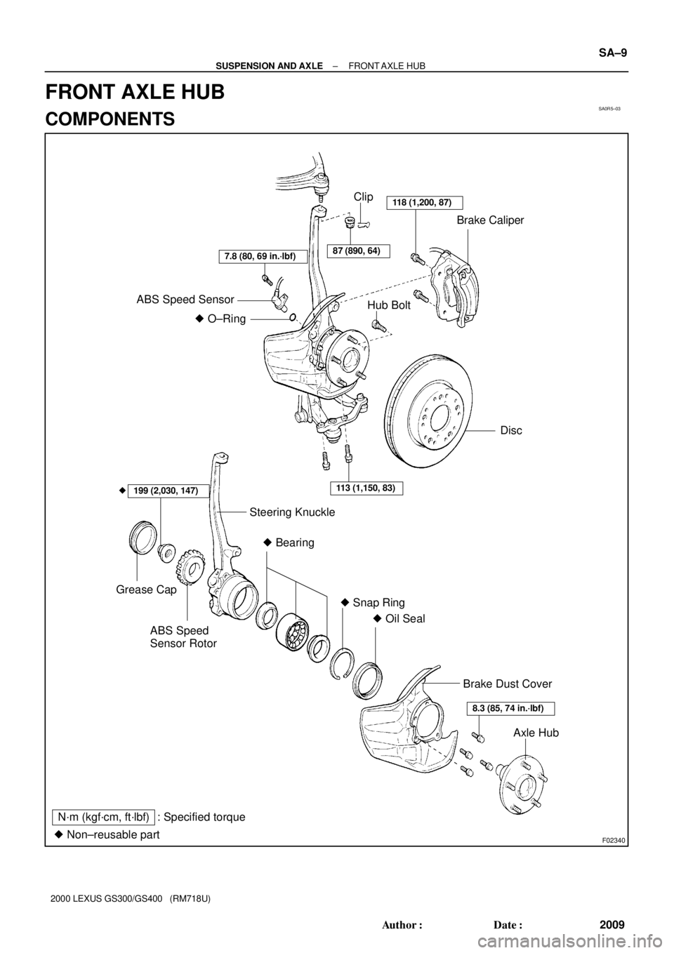
SA0R5±03
F02340
Clip
Brake Caliper
ABS Speed Sensor
Hub Bolt
Disc
Steering Knuckle
Grease Cap
ABS Speed
Sensor Rotor� Snap Ring
� Oil Seal
Brake Dust Cover
Axle Hub
� Bearing
� O±Ring
87 (890, 64)
118 (1,200, 87)
7.8 (80, 69 in.´lbf)
113 (1,150, 83)199 (2,030, 147)
8.3 (85, 74 in.´lbf)
�
� Non±reusable part: Specified torque
N´m (kgf´cm, ft´lbf)
± SUSPENSION AND AXLEFRONT AXLE HUB
SA±9
2009 Author�: Date�:
2000 LEXUS GS300/GS400 (RM718U)
FRONT AXLE HUB
COMPONENTS
Page 1105 of 1111
SA0SP±01
F03424
Upper Suspension Arm
64 (650, 47)
88 (900, 65)
18 (185, 13)
88 (900, 65)
Shock Absorber With
Coil Spring
Washer
Drive Shaft
Suspension Member Brace
110 (1,120, 81)
30 (305, 22)
289 (2,950, 213)
50 (510, 37)
X6
HID Type Headlight:
Height Control
Sensor Link
N´m (kgf´cm, ft´lbf) : Specified torque
� Non±reusable part� Cotter Pin
Lock Cap
110 (1,120, 81)
110 (1,120, 81)
No.2 Lower Suspension Arm
83 (850, 61)
108 (1,100, 80)
75 (765, 55)
± SUSPENSION AND AXLEREAR UPPER SUSPENSION ARM
SA±93
2093 Author�: Date�:
2000 LEXUS GS300/GS400 (RM718U)
REAR UPPER SUSPENSION ARM
COMPONENTS
Page 1106 of 1111
SA0SQ±01
F02383
SST
F02384
SA±94
± SUSPENSION AND AXLEREAR UPPER SUSPENSION ARM
2094 Author�: Date�:
2000 LEXUS GS300/GS400 (RM718U)
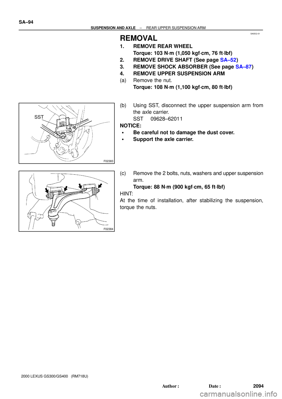
REMOVAL
1. REMOVE REAR WHEEL
Torque: 103 N´m (1,050 kgf´cm, 76 ft´lbf)
2. REMOVE DRIVE SHAFT (See page SA±52)
3. REMOVE SHOCK ABSORBER (See page SA±87)
4. REMOVE UPPER SUSPENSION ARM
(a) Remove the nut.
Torque: 108 N´m (1,100 kgf´cm, 80 ft´lbf)
(b) Using SST, disconnect the upper suspension arm from
the axle carrier.
SST 09628±62011
NOTICE:
�Be careful not to damage the dust cover.
�Support the axle carrier.
(c) Remove the 2 bolts, nuts, washers and upper suspension
arm.
Torque: 88 N´m (900 kgf´cm, 65 ft´lbf)
HINT:
At the time of installation, after stabilizing the suspension,
torque the nuts.
Page 1107 of 1111
SA0SR±01
F01986
± SUSPENSION AND AXLEREAR UPPER SUSPENSION ARM
SA±95
2095 Author�: Date�:
2000 LEXUS GS300/GS400 (RM718U)
INSPECTION
INSPECT BALL JOINT FOR ROTATION CONDITION
(a) As shown, flip the ball joint stud back and forth 5 times,
before installing the nut.
(b) Using torque wrench, turn the nut continuously one turn
per 2 ± 4 seconds and take the torque reading on the 5th
turn.
Turning torque:
1.0 ± 3.4 N´m (10 ± 35 kgf´cm, 9 ± 30 in.´lbf)


88 (900, 65)
18 (185, 13)
88 (900, 65)
Shock Absorber With
Coil Spring
Washer
Drive Shaft
Suspension Member Brace
110 (1,120, 81)
30 (305, 22)
289 (2")