Page 1042 of 1111

REMOVAL
1. REMOVE FRONT WHEEL
Torque: 103 N´m")
SA0RN±01
F02311
F02312
SST
F02317
F02318
SA±30
± SUSPENSION AND AXLEFRONT LOWER SUSPENSION ARM
2030 Author�: Date�:
2000 LEXUS GS300/GS400 (RM718U)
REMOVAL
1. REMOVE FRONT WHEEL
Torque: 103 N´m (1,050 kgf´cm, 76 ft´lbf)
2. REMOVE ENGINE UNDER COVERS
3. REMOVE BRAKE CALIPER
(a) Remove the 2 bolts and caliper.
Torque: 118 N´m (1,200 kgf´cm, 87 ft´lbf)
(b) Support the brake caliper securely.
(c) Remove the disc.
4. DISCONNECT TIE ROD END
(a) Remove the clip and nut.
Torque: 87 N´m (890 kgf´cm, 64 ft´lbf)
(b) Using SST, disconnect the tie rod end from the steering
knuckle.
SST 09610±20012
5. HID TYPE HEADLIGHT:
DISCONNECT HEIGHT CONTROL SENSOR LINK
FROM SHOCK ABSORBER BRACKET
Remove the nut and disconnect the height control sensor link
from the shock absorber bracket.
Torque: 5.4 N´m (55 kgf´cm, 48 in.´lbf)
6. REMOVE STABILIZER BAR LINK
(a) Remove the bolt and nut, disconnect the stabilizer bar link
from the stabilizer bar.
Torque: 55 N´m (560 kgf´cm, 43 ft´lbf)
(b) Remove the nut and stabilizer bar link.
Torque: 113 N´m (1,150 kgf´cm, 83 ft´lbf)
Page 1052 of 1111

FRONT WHEEL ALIGNMENT
INSPECTION
1. MEASU")
F02399
FRONT
REARSA0R3±01
Z03382
SA3213
A
DB
C Front
SA±4
± SUSPENSION AND AXLEFRONT WHEEL ALIGNMENT
2004 Author�: Date�:
2000 LEXUS GS300/GS400 (RM718U)
FRONT WHEEL ALIGNMENT
INSPECTION
1. MEASURE VEHICLE HEIGHT
Tire sizeFront*1 mm (in.)Rear*2 mm (in.)
P215/60R16 94V245 (9.63)226 (8.90)
225/55R16 94V240 (9.45)221 (8.70)
235/45ZR17238 (9.37)219 (8.62)
*1: Front measuring point
Measure from the ground to the center of the lower suspension
arm mounting bolt.
*
2: Rear measuring point
Measure from the ground to the center of the No.2 lower sus-
pension arm mounting bolt.
NOTICE:
Before inspecting the wheel alignment, adjust the vehicle
height to the specification.
If the vehicle height is not within the specification, try to adjust
it by pushing down on or lifting the body.
2. INSTALL CAMBER±CASTER±KINGPIN GAUGE
ONTO WHEEL ALIGNMENT TESTER
Follow the specific instructions of the equipment manufacturer.
3. INSPECT CAMBER, CASTER AND STEERING AXIS
INCLINATION
Camber
Left±right error±0°16' ± 30' (±0.27° ± 0.5°)
30' (0.5°) or less
Caster
Left±right error7°33' ± 30' (7.55° ± 0.5°)
30' (0.5°) or less
Steering axis inclination
Left±right error8°52' ± 30' (8.87°± 0.5°)
30' (0.5°) or less
If the camber is not within the specification, adjust it by adjusting
cam.
4. INSPECT TOE±IN
Toe±in
(total)A + B: 0°09' ± 12' (0.15° ± 0.2°)
C ± D: 1.5 ± 2 mm (0.06 ± 0.08 in.)
If the toe±in is not within the specification, adjust it at the tie rod
end.
Page 1085 of 1111

REAR WHEEL ALIGNMENT
INSPECTION
1. MEASURE VEHIC")
SA0R4±01
SA3213
D AB
C Front
F03479
A
B
F02401
± SUSPENSION AND AXLEREAR WHEEL ALIGNMENT
SA±7
2007 Author�: Date�:
2000 LEXUS GS300/GS400 (RM718U)
REAR WHEEL ALIGNMENT
INSPECTION
1. MEASURE VEHICLE HEIGHT (See page SA±4)
2. INSTALL CAMBER±CASTER±KINGPIN GAUGE
ONTO WHEEL ALIGNMENT TESTER
Follow the specific instructions of the equipment manufacturer.
3. INSPECT CAMBER
Camber
Left±right error±0°47' ± 30' (±0.78° ± 0.5°)
30' (0.5°) or less
4. INSPECT TOE±IN
Toe±in
(total)A + B: 0°08' ± 12' (0.13° ± 0.2°)
C ± D: 1.4 ± 2 mm (0.056 ± 0.08 in.)
5. ADJUST CAMBER AND TOE±IN
(a) Measure the lengths of the toe control link and No.2 lower
suspension arm, as shown in the illustration.
Length: A ± B = 4.0 mm (0.16 in.) or less
If they are not within the specifications, adjust the lengths of
them by turning the adjusting cam, as shown, until (A ± B) is less
than 4.0 mm (0.16 in.).
(b) Measure the camber and toe±in.
(c) Adjust the camber.
(1) Loosen the camber adjusting cam nut of lower sus-
pension arm No.2.
(2) Turn the camber adjusting cam of lower suspension
arm No.2 and adjust camber.
HINT:
Camber changes about 5.0' (0.08°) with each graduation of the
cam.
(3) Torque the camber adjusting cam nut.
Torque: 110 N´m (1,120 kgf´cm, 81 ft´lbf)
Page 1101 of 1111
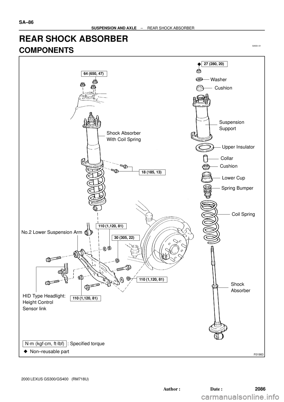
SA0SI±01
F01983
64 (650, 47)
27 (280, 20)
18 (185, 13)
�
Shock Absorber
With Coil SpringWasher
Cushion
Suspension
Support
Upper Insulator
Collar
Cushion
Spring Bumper
Coil Spring
110 (1,120, 81)
110 (1,120, 81)HID Type Headlight:
Height Control
Sensor linkShock
Absorber No.2 Lower Suspension Arm
N´m (kgf´cm, ft´lbf) : Specified torque
Non±reusable part �
110 (1,120, 81)
30 (305, 22)
Lower Cup
SA±86
± SUSPENSION AND AXLEREAR SHOCK ABSORBER
2086 Author�: Date�:
2000 LEXUS GS300/GS400 (RM718U)
REAR SHOCK ABSORBER
COMPONENTS
Page 1105 of 1111
SA0SP±01
F03424
Upper Suspension Arm
64 (650, 47)
88 (900, 65)
18 (185, 13)
88 (900, 65)
Shock Absorber With
Coil Spring
Washer
Drive Shaft
Suspension Member Brace
110 (1,120, 81)
30 (305, 22)
289 (2,950, 213)
50 (510, 37)
X6
HID Type Headlight:
Height Control
Sensor Link
N´m (kgf´cm, ft´lbf) : Specified torque
� Non±reusable part� Cotter Pin
Lock Cap
110 (1,120, 81)
110 (1,120, 81)
No.2 Lower Suspension Arm
83 (850, 61)
108 (1,100, 80)
75 (765, 55)
± SUSPENSION AND AXLEREAR UPPER SUSPENSION ARM
SA±93
2093 Author�: Date�:
2000 LEXUS GS300/GS400 (RM718U)
REAR UPPER SUSPENSION ARM
COMPONENTS
Page 1109 of 1111
SA0ST±01
F03426
Fender Apron Seal
No.2 Lower
Suspension Arm
HID Type Headlight:
Height Control
Sensor Link
110 (1,120, 81)
30 (305, 22)
110 (1,120, 81)
110 (1,120, 81)
No.1 Lower Suspension Arm
75 (765, 55)
N´m (kgf´cm, ft´lbf): Specified torque
75 (765, 55)
± SUSPENSION AND AXLEREAR LOWER SUSPENSION ARM
SA±97
2097 Author�: Date�:
2000 LEXUS GS300/GS400 (RM718U)
REAR LOWER SUSPENSION ARM
COMPONENTS
Page 1110 of 1111

REMOVAL
1. REMOVE REAR WHEEL
Torque: 103 N´m (1,050 kgf´c")
SA0SU±01
F02385
F02386
F02387
SA±98
± SUSPENSION AND AXLEREAR LOWER SUSPENSION ARM
2098 Author�: Date�:
2000 LEXUS GS300/GS400 (RM718U)
REMOVAL
1. REMOVE REAR WHEEL
Torque: 103 N´m (1,050 kgf´cm, 76 ft´lbf)
2. REMOVE REAR FENDER APRON SEAL
3. REMOVE NO.1 LOWER SUSPENSION ARM
Remove the 2 bolts, nuts, and No.1 lower suspension arm.
Torque: 75 N´m (765 kgf´cm, 55 ft´lbf)
HINT:
At the time of installation, after stabilizing the suspension,
torque the nuts.
4. REMOVE NO.2 LOWER SUSPENSION ARM
(a) Halogen type headlight:
Remove the bolt, nut and disconnect the stabilizer bar link
from the No.2 lower suspension arm.
Torque: 30 N´m (305 kgf´cm, 22 ft´lbf)
(b) HID type headlight:
Remove the bolt, nut and disconnect the stabilizer bar link
and the height control link from the No.2 lower suspen-
sion arm.
Torque: 30 N´m (305 kgf´cm, 22 ft´lbf)
(c) Remove the bolt, nut and disconnect the shock absorber
from the No.2 lower suspension arm.
Torque: 110 N´m (1,120 kgf´cm, 81 ft´lbf)
HINT:
At the time of installation, after stabilizing the suspension,
torque the nut.
Page:
< prev 1-8 9-16 17-24

88 (900, 65)
18 (185, 13)
88 (900, 65)
Shock Absorber With
Coil Spring
Washer
Drive Shaft
Suspension Member Brace
110 (1,120, 81)
30 (305, 22)
289 (2")

30 (305, 22)
110 (1,120, 81)
110 (1,120, 81)
No.1 Lower Suspension Arm
75 (")