Page 626 of 1111

Diagnostic trouble code check
Making a note of and clearing of the diagnostic trouble codes displayed
Symptom confirmation
No problem symptoms
exist Problem symptoms
exist
Simulation test using the symptom
simulation methods
� Normal code displayed
� Problem symptoms exist� Normal code displayed
� No problem symptoms exist Diagnostic trouble code check
Troubleshooting of problem indicated
by diagnostic trouble code� Diagnostic trouble code displayed
� Problem symptoms exist
System Normal Troubleshooting of each
problem symptom
If a diagnostic trouble code was
displayed in the initial diagnostic
trouble code check, it indicates
that the trouble may have occurred
in a wire harness or connector in
that circuit in the past. Therefore,
check the wire harness and con-
nectors (See page IN±31).
IN±24± INTRODUCTIONHOW TO TROUBLESHOOT ECU CONTROLLED
SYSTEMS
24 Author�: Date�:
2000 LEXUS GS300/GS400 (RM718U)
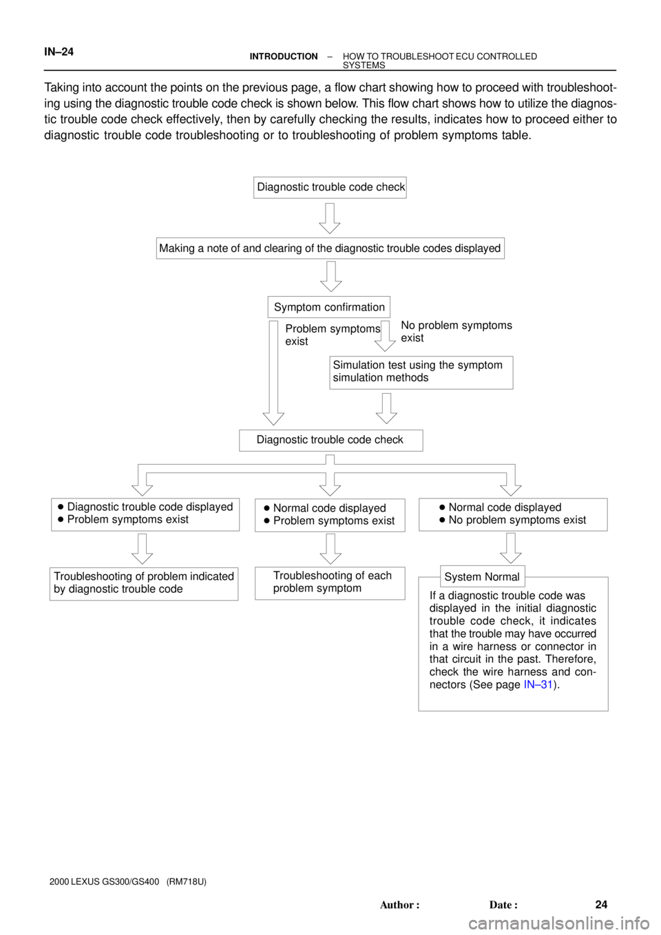
Taking into account the points on the previous page, a flow chart showing how to proceed with troubleshoot-
ing using the diagnostic trouble code check is shown below. This flow chart shows how to utilize the diagnos-
tic trouble code check effectively, then by carefully checking the results, indicates how to proceed either to
diagnostic trouble code troubleshooting or to troubleshooting of problem symptoms table.
Page 629 of 1111

� DTC No.
Indicates the diagnostic trouble code.
� Page or Instructions
Indicates the page where the inspection procedure
for each circuit is to be found, or gives instructions
for checking and repairs.
� Detection Item
Indicates the system of the problem or
contents of the problem.� Trouble Area
Indicates the suspect area of the
problem.
Mass Air Flow Circuit MalfunctionDetection Item
� Open or short in mass air flow meter circuit
� Mass air flow meter
� ECM DTC No.
(See page)Trouble AreaMIL* MemoryP0100
(DI±24)
P0101
(DI±28)
P0115
(DI±33)� Open or short in intake air temp. sensor
circuit
� Intake air temp. sensor
� ECM Intake Air Temp. Circuit
Malfunction P0110
(DI±29)
� Open or short in engine coolant temp. sensor circuit
� Engine coolant temp. sensor
� ECM
Throttle/ Pedal Position Sensor/Switch
ºAº Circuit MalfunctionEngine Coolant Temp.
Circuit Malfunction
� Open or short in throttle position sensor circuit
� Throttle position sensor
� ECM
DTC CHART (SAE Controlled)
HINT:
Parameters listed in the chart may not be exactly the same as your reading due to the type of instrument or other
factors.
If a malfunction code is displayed during the DTC check mode, check the circuit for that code listed in the table
below. For details of each code, turn to the page referred to under the ºSee pageº for the respective ºDTC No.º
in the DTC chart.
Mass Air Flow Circuit
Range/ Performance Problem� Mass air flow meter
� Throttle position sensor Throttle/ Pedal Position Sensor/ Switch
ºAº Circuit Range / Performance Prob-
lem P0116
(DI±37)Engine Coolant Temp.
Circuit Range/ Performance Problem� Engine coolant temp. sensor
� Cooling system
± INTRODUCTIONHOW TO TROUBLESHOOT ECU CONTROLLED
SYSTEMSIN±27
27 Author�: Date�:
2000 LEXUS GS300/GS400 (RM718U)
4. DIAGNOSTIC TROUBLE CODE CHART
The inspection procedure is shown in the table below. This table permits efficient and accurate troubleshoot-
ing using the diagnostic trouble codes displayed in the diagnostic trouble code check. Proceed with trouble-
shooting in accordance with the inspection procedure given in the diagnostic chart corresponding to the
diagnostic trouble codes displayed. The engine diagnostic trouble code chart is shown below as an example.
Page 630 of 1111

IN±28± INTRODUCTIONHOW TO TROUBLESHOOT ECU CONTROLLED
SYSTEMS
28 Author�: Date�:
2000 LEXUS GS300/GS400 (RM718U)
5. PROBLEM SYMPTOMS TABLE
The suspected circuits or parts for each problem symptom are shown in the table below. Use this table to
troubleshoot the problem when a ºNormalº code is displayed in the diagnostic trouble code check but the
problem is still occurring. Numbers in the table indicate the inspection order in which the circuits or parts
should be checked.
HINT:
When the problem is not detected by the diagnostic system even though the problem symptom is present,
it is considered that the problem is occurring outside the detection range of the diagnostic system, or that
the problem is occurring in a system other than the diagnostic system.
Symptom
Suspect AreaSee page
Engine does not crank (Does not start)
No initial combustion (Does not start)
No complete combustion (Does not start)1. Starter and starter relay
1. ECM power source circuit
2. Fuel pump control circuit
3. Engine control module (ECM)
1. Starter signal circuit
2. Fuel pump control circuit1. Fuel pump control circuitDI±147
DI±151
IN±29
PROBLEM SYMPTOMS TABLE
1. Compression
2. Fuel pump control circuit 1. A/C signal circuit
2. Fuel pump control circuit 1. A/C signal circuit (Compressor circuit)
2. ECM power source circuit 1. Starter signal circuit
2. Fuel pump control circuit1. Starter signal circuit
2. Fuel pump control circuit
3. Compression
idling) High engine idle speed (Poor idling) Hot engine Cold engine (Difficult to start)Engine cranks normally (Difficult to start)
AC±88 DI±144
DI±151
EM±3 DI±151
� Problem Symptom� Page
Indicates the page where the flow chart for each circuit
is located.
� Circuit Inspection, Inspection Order
Indicates the circuit which needs to be checked for each problem
symptom. Check in the order indicated by the numbers.
� Circuit or Part Name
Indicates the circuit or part which needs to be checked.
ST±2
ST±17
DI±144
DI±151
DI±144
DI±151
Page 641 of 1111

IN±38
± INTRODUCTIONTERMS
38 Author�: Date�:
2000 LEXUS GS300/GS400 (RM718U) H±FUSE
High Current Fuse
HIHigh
HIDHigh Intensity Discharge (Head Lamp)
HSGHousing
HTHard Top
HWSHeated Windshield System
IACIdle Air Control
ICIntegrated circuit
IDIIndirect Diesel Injection
IFSIndependent Front Suspension
IGIgnition
IIAIntegrated Ignition Assembly
INIntake (Manifold, Valve)
INTIntermittent
I/PInstrument Panel
IRSIndependent Rear Suspension
J/BJunction Block
J/CJunction Connector
KDKick±Down
LANLocal Area Network
LBLiftback
LCDLiquid Crystal Display
LEDLight Emitting Diode
LHLeft±Hand
LHDLeft±Hand Drive
L/H/WLength, Height, Width
LLCLong±Life Coolant
LNGLiquified Natural Gas
LOLow
LPGLiquified Petroleum Gas
LSDLimited Slip Differential
LSP & PVLoad Sensing Proportioning And Bypass Valve
LSPVLoad Sensing Proportioning Valve
MAX.Maximum
MICMicrophone
MILMalfunction Indicator Lamp
MIN.Minimum
MPMultipurpose
MPXMultiplex Communication System
M/TManual Transmission
MTMount
MTGMounting
NNeutral
NANatural Aspiration
No.Number
O/DOverdrive