Page 509 of 1111
EVAPORATIVE EMISSION (EVAP) CONTROL SYSTEM
1459 Author�: Date�:
2000 LEXUS GS300/GS400 (RM71")
B06545
B06743Hose ClipperAir Drain Hose
B06546
Pressure
Gauge
Pressure EC±8
± EMISSION CONTROL (2JZ±GE)EVAPORATIVE EMISSION (EVAP) CONTROL SYSTEM
1459 Author�: Date�:
2000 LEXUS GS300/GS400 (RM718U)
(e) Check the vacuum at idle.
Vacuum:
Maintain at 0.368 ± 19.713 in.Hg (5 ± 268 in.Aq) for over
5 seconds
HINT:
If the vacuum does not change, you can conclude that the hose
connecting the VSV to the service port has come loose or is
blocked, or the VSV is malfunctioning.
(f) LEXUS Hand±Held Tester:
Conclude forced driving of the VSV for the EVAP.
(1) Stop the engine.
(2) Disconnect the LEXUS hand±held tester from the
DLC3.
(g) If you have no LEXUS Hand±Held Tester:
Conclude forced driving of the VSV for the EVAP.
(1) Stop the engine.
(2) Disconnect the positive (+) and negative (±) leads
from the battery from the VSV terminals for the
EVAP.
(3) Connect the VSV connector for the EVAP.
(h) Disconnect the vacuum gauge from the EVAP service
port on the purge line.
(i) Connect a pressure gauge to the EVAP service port on
the purge line.
(j) Check the pressure.
(1) Close off the air drain hose at the marked position
of the canister with a hose clipper or similar instru-
ment.
(2) Add the pressure (13.5 ± 15.5 in.Aq) from the EVAP
service port.
Pressure:
2 minutes after the pressure is added, the gauge
should be over 7.7 ± 8.8 in.Aq.
HINT:
If you can't add pressure, you can conclude that the hose con-
necting the VSV�canister�fuel tank has slipped off or the
VSV is open.
Page 513 of 1111
CO/HC
EM±1
1355 Author�: Date�:
2000 LEXUS GS300/GS400 (RM718U)
CO/HC
INSPECTION
HINT:
This check is used only to determine whether or not")
EM0D0±01
A00982
CO/HC Meter
± ENGINE MECHANICAL (2JZ±GE)CO/HC
EM±1
1355 Author�: Date�:
2000 LEXUS GS300/GS400 (RM718U)
CO/HC
INSPECTION
HINT:
This check is used only to determine whether or not the idle
CO/HC complies with regulations.
1. INITIAL CONDITIONS
(a) Engine at normal operating temperature
(b) Air cleaner installed
(c) All pipes and hoses of air induction system connected
(d) All accessories switched OFF
(e) All vacuum lines properly connected
(f) SFI system wiring connectors fully plugged
(g) Ignition timing checked correctly
(h) Transmission in neutral position
(i) Tachometer and CO/HC meter calibrated by hand
2. START ENGINE
3. RACE ENGINE AT 2,500 RPM FOR APPROX. 180
SECONDS
4. INSERT CO/HC METER TESTING PROBE AT LEAST
40 cm (1.3 ft) INTO TAILPIPE DURING IDLING
5. IMMEDIATELY CHECK CO/HC CONCENTRATION AT
IDLE AND/OR 2,500 RPM
HINT:
When doing the 2 mode (2,500 rpm and idle) test, follow the
measurement order prescribed by the applicable local regula-
tions.
Page 514 of 1111
CO/HC
1356 Author�: Date�:
2000 LEXUS GS300/GS400 (RM718U)
If the CO/HC concentration does not comply with regulations,
troubleshoot in the order given below.
(a)")
EM±2
± ENGINE MECHANICAL (2JZ±GE)CO/HC
1356 Author�: Date�:
2000 LEXUS GS300/GS400 (RM718U)
If the CO/HC concentration does not comply with regulations,
troubleshoot in the order given below.
(a) Check heated oxygen sensors operation.
(See page DI±44)
(b) See the table below for possible causes, and then inspect
and correct the applicable causes if necessary.
HCCOPhenomenonCauses
HighNormalRough idle1. Faulty ignitions:
�Incorrect timing
�Fouled, shorted or improperly gapped plugs
�Open or crossed high±tension cords
2. Incorrect valve clearance
3. Leaky intake and exhaust valves
4. Leaky cylinder
HighLowRough idle
(Fluctuating HC reading)1. Vacuum leaks:
�PCV hose
�Intake manifold
�Throttle body
�Cylinder head gasket
2. Lean mixture causing misfire
HighHighRough idle
(Black smoke from exhaust)1. Restricted air filter
2. Plugged PCV valve
3. Faulty SFI systems:
�Faulty pressure regulator
�Faulty ECM
�Faulty injector
�Faulty throttle position sensor
�Faulty mass air flow meter
Page 515 of 1111
IGNITION TIMING
1366 Author�: Date�:
2000 LEXUS GS300/GS400")
B01982
LEXUS
Hand±Held
Tester
EM0D3±02
A02667
TC
E1 SST
DLC1
A02668
Igniter
White Lead Wire
A02637
EM±12
± ENGINE MECHANICAL (2JZ±GE)IGNITION TIMING
1366 Author�: Date�:
2000 LEXUS GS300/GS400 (RM718U)
IGNITION TIMING
INSPECTION
1. WARM UP ENGINE
Allow the engine to warm up to normal operating temperature.
2. CONNECT LEXUS HAND±HELD TESTER OR OBDII
SCAN TOOL
(a) Connect the LEXUS hand±held tester or OBDII scan tool
to the DLC3.
(b) Please refer to the LEXUS hand±held tester or OBDII
scan tool operator's manual for further details.
3. CONNECT TIMING LIGHT TO ENGINE
4. CHECK IDLE SPEED (See page EM±13)
5. INSPECT IGNITION TIMING
(a) Using SST, connect terminals TC and E1 of the DLC1.
SST 09843±18020
(b) Connect the timing light clip to the white lead wire.
NOTICE:
Use a timing light that can detect the primary signal.
(c) Using a timing light, check the ignition timing.
Ignition timing: 10 ± 2° BTDC @ idle
(Transmission in neutral position)
(d) Remove the SST from the DLC1.
6. FURTHER CHECK IGNITION TIMING
Ignition timing: 6 ± 16° BTDC @ idle
(Transmission in neutral position)
HINT:
The timing mark moves in a range between 6° and 16°.
7. DISCONNECT TIMING LIGHT FROM ENGINE
8. DISCONNECT LEXUS HAND±HELD TESTER OR
OBDII SCAN TOOL
Page 516 of 1111
EM0D4±01
± ENGINE MECHANICAL (2JZ±GE)IDLE SPEED
EM±13
1367 Author�: Date�:
2000 LEXUS GS300/GS400 (RM718U)
IDLE SPEED
INSPECTION
1. INITIAL CONDITIONS
(a) Engine at normal operating temperature
(b) Air cleaner installed
(c) All pipes and hoses of air induction system connected
(d) All accessories switched OFF
(e) All vacuum lines properly connected
(f) SFI system wiring connectors fully plugged
(g) Ignition timing checked correctly
(h) Transmission in neutral position
2. CONNECT LEXUS HAND±HELD TESTER OR OBDII SCAN TOOL (See page EM±12)
3. INSPECT IDLE SPEED
(a) Race the engine speed at 2,500 rpm for approx. 90 seconds.
(b) Check the idle speed.
Idle speed: 700 ± 50 rpm
If the idle speed is not as specified, check the throttle body.
4. DISCONNECT LEXUS HAND±HELD TESTER OR OBDII SCAN TOOL
Page 517 of 1111
EM0D5±03
A09758
Air Cleaner Inlet
Air Cleaner, MAF Meter and Intake
Air Resonator Assembly
PCV Hose
MAF Meter
Connector
PS Air Hose
Engine Wire
Clamp
EVAP HoseRadiator Assembly
Lower Radiator Hose
Upper Radiator Support
ECM
Outlet Duct
Wire Clamp
ECT Switch
Connector
Electric
Cooling Fan
Connector
Oil Cooler Hose
for A/T Accelerator Cable
PS Vane Pump
PS Pump
Front Bracket
Drive Belt
Engine Under Cover
N´m (kgf´cm, ft´lbf) : Specified torque
� Non±reusable Part
Lower Radiator
Support
Upper Radiator Hose
58 (590, 43)
52 (530, 38)
x 18
Engine Cover EM±14
± ENGINE MECHANICAL (2JZ±GE)TIMING BELT
1368 Author�: Date�:
2000 LEXUS GS300/GS400 (RM718U)
TIMING BELT
COMPONENTS
Page 518 of 1111

A11128
Accelerator Pedal Position Sensor Connector
Throttle Control Motor Connector
Throttle Body and Intake Air Connector Assembly
Water Bypass HoseVSV Connector
for EVAP
EVAP Hose
� Gasket Air Assist Hose Engine Wire
Oil Filler Cap
No.3 Timing Belt Cover
Gasket
No.2 Timing Belt Cover
GasketThrottle
Position
Sensor
Connector
Vacuum Hose
(from Actuator for ACIS)
Water Bypass Hose
Engine Wire Protector
High±Tension
Cord w/ Clamp
No.1 Cylinder
Head Cover
Gasket
Timing Belt
x 6
Timing Belt Guide
Gasket
x 5 No.1 Timing Belt Cover
Crankshaft
Pulley
21 (210, 15)
Drive Belt Tensioner
330 (3,300, 243)
Camshaft
Timing Pulley
(VVT±i Pulley)81 (810, 60)
Straight
Screw Plug
15 (150, 11)Seal Washer
Camshaft
Timing Oil
Control Valve
Camshaft Timing
Oil Control
Valve Connector� Gasket
Oil Control Valve Filter
� O±Ring
No.1 Oil PipeUnion Bolt
55 (550, 41)
Idler Pulley
Crankshaft Timing Pulley
Timing Belt Plate
Timing Belt Tensioner
N´m (kgf´cm, ft´lbf) : Specified torque
35 (350, 26)�
8.0 (80, 71 in.´lbf)
27 (270, 20)
� Non±reusable part
� Precoated part
Dust Boot
Engine Wire ClampPCV Hose
Vacuum Hose
(from No.2
Vacuum Pipe)
± ENGINE MECHANICAL (2JZ±GE)TIMING BELT
EM±15
1369 Author�: Date�:
2000 LEXUS GS300/GS400 (RM718U)
Page 519 of 1111
EM0D6±04
A01482
A02663
5 mm Hexagon Wrench
A02649
A02690
SST
EM±16
± ENGINE MECHANICAL (2JZ±GE)TIMING BELT
1370 Author�: Date�:
2000 LEXUS GS300/GS400 (RM718U)
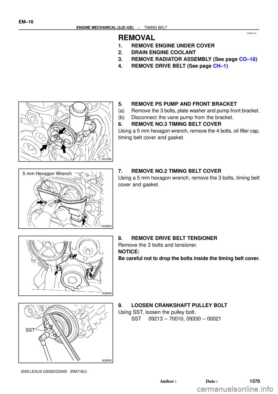
REMOVAL
1. REMOVE ENGINE UNDER COVER
2. DRAIN ENGINE COOLANT
3. REMOVE RADIATOR ASSEMBLY (See page CO±18)
4. REMOVE DRIVE BELT (See page CH±1)
5. REMOVE PS PUMP AND FRONT BRACKET
(a) Remove the 3 bolts, plate washer and pump front bracket.
(b) Disconnect the vane pump from the bracket.
6. REMOVE NO.3 TIMING BELT COVER
Using a 5 mm hexagon wrench, remove the 4 bolts, oil filler cap,
timing belt cover and gasket.
7. REMOVE NO.2 TIMING BELT COVER
Using a 5 mm hexagon wrench, remove the 3 bolts, timing belt
cover and gasket.
8. REMOVE DRIVE BELT TENSIONER
Remove the 3 bolts and tensioner.
NOTICE:
Be careful not to drop the bolts inside the timing belt cover.
9. LOOSEN CRANKSHAFT PULLEY BOLT
Using SST, loosen the pulley bolt.
SST 09213 ± 70010, 09330 ± 00021