Page 1091 of 1395
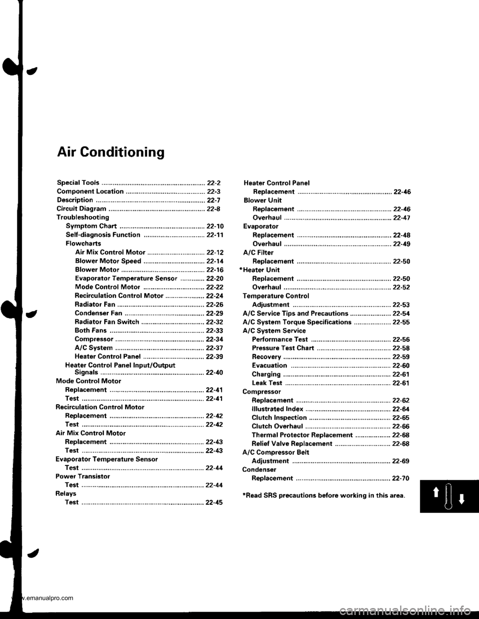
Air Conditioning
Heater Control Panel
Reofacement ,.,...,,.,..,.,.,,22-46
Blower Unit
Replacement .................. 22-46
Overhaul ...........,,,., .......-.22-17
Evaporalor
ReDlacement ...,.,.,..,......,22-4A
Overhaul ................ .........22-19
A/C Filter
Replacement ..................22-50*Heater Unit
ReDfacement ..................22-50
Overhaul ..,.,..,.,...,.. .........22-52
Temperature Control
Adiustment ....................22-53
A/C Service Tips and Precauiions............-....-.... 22-54
A/C System Torque Specifications .................... 22-55
A/C System Service
Performance Test ......,...22-56
Pressure Test Chart .-.....22-5a
Recovery ..............,. ...-.-...22-59
Evacuation -...........-........22-60
Charging ................ .......-.22-61
Leak Test ........................22-61
Compressor
Repfacement ..........-.......22-62
flfustrated Index .....,.......22-64
Cfutch fnspection .........,.22-65
Cfutch Overhaul ............- 22-66
Thermaf Protector Rep|acement ................... 22-68
Refief Valve Replacement .............................. 22-68
A/C Comoressor Belt
Adiustment .................... 22-69
Condenser
Repfacement .,.....,,.,..,.,..22-70
'Read SRS precautions betore working in this area.
www.emanualpro.com
Page 1094 of 1395
Component Location
lndex (cont'dl
SRS components are located in this area. Review the SRS component locations, precautions, and procedures in the SRS
section (24) before performing repairs or service.
BLOWER UNITReplacement, page 22-46Ovethaul, page 22 47
/alowen ruoronl
\Test, page 22-16 /
EVAPORATORFeplacement, page 22-48Overhaul, page 22,49
RECIRCULATIONCONTROL MOTORReplacement, page 22 42
HEATER UNITReplacement, page 22 50Overhaul, page 22 52
lest, pag.e 22 42
A/C FILIERReplacement. page 22-50VALVE CABLEAdjustment, page 22-53
RECIRCULATIONCONTROL SWITCH
a/c swtTcH
MODEMOTOR
REAR WINDOWDEFOGGERSwlTCHSee section 23Replacement, page 22-41Test, page 22-41MODE CONTROLDIAL
HEATER CONTROLPANELReplacement, page 22 46
swtTcH
22-4
CONTROL
www.emanualpro.com
Page 1096 of 1395
Component Location
Index (cont'dl
SRS components are located in this area. Review the SRS component locations, precautions, and procedures in the SRS
section (24) before performing repairs or service.
BECIRCULATION CONTROL MOTOR4P CONNECTOR
EVAPORATOR TEMPERATURE SENSORTesl, page 22-44POWER TRANSISTOR3P CONNECTOR
AIR MIX CONTROL MOTORReplacement, page 22-43lest, page 22-13
BLOWER MOTOB2P CONNECTOR
BLOWER MOTOR HIGH RELAYTest, page 22-45
HEATER SUB.HARNESS
7P CONNECTOR
DASHBOARD WIRE HARNESS
HEATER CONTROL PANEL8P AND 2OP CONNECYORS
22-6
www.emanualpro.com
Page 1099 of 1395
cnNj@_snN
GRY
PNK/BLK
NED/8LU
REO/YEL
YEL/BLU
8RN/WHT
GRNI/VHT
GRN/RED
POWERTRANSISTOR
c401c402
22-9
4
ORNMHT
Fg"{
EVAPONATORTEMPERATURE SENSOR
fi3'.Hfi|$l#i9D>
"'"-
DASH LTGHTS _/4EE|GHTNESS < l_ REDCONTROLLER -!
REAR
fllf$!S,* (l aLurrLRELAY
O:8P coNNEcToR
n :20P c0NN€CToR
YEL/RED
GRN/YEL
8LU/8LK
BRN
YEL
s5v s coM
AMD P AIR MIXCONTROLMOTOB
HOT
VENT
B/LI/lODEH CONT8OLl
10T0RH/D MDEF
HEATER CONTROL PANEI-
8LK
www.emanualpro.com
Page 1100 of 1395
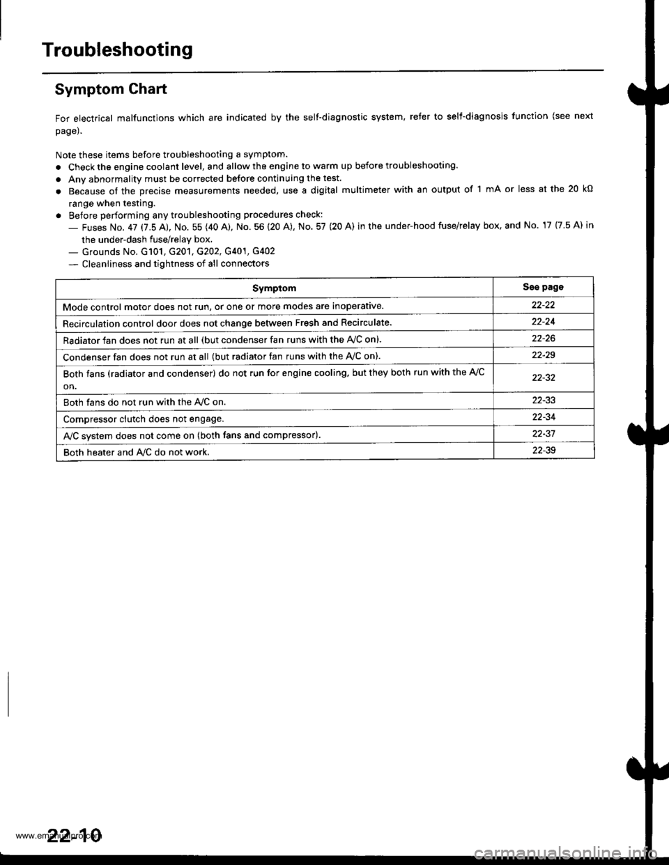
Troubleshooting
Symptom Ghart
For electrical malfunctions which are indicated by the self-diagnostic system, reter to selt-diagnosjs function (see next
page).
Note these items before troubleshooting a symptom.
. Check the engine coolant level, and allow the engine to warm up before troubleshooting.
. Anv abnormality must be corrected before continuing the test.
. Because of the precise measurements needed, use a digital multimeter with an output of 1 mA or less at the 20 kO
range when testing.
. Before performing any troubleshooting procedures check:
- Fuses No. 47 17.5 AJ, No. 55 (40 A), No. 56 (20 A), No. 57 (20 A) in the under-hood fuse/relay box, and No. 17 {7.5 A) in
the under-dash fuse/relay box.._ Grounds No. G101, G201, G202, G401, G4O2
- Cleanliness and tightness of all connectors
SymptomSse pags
Mode control motor does not run, or one or more modes are inoperative.
Recirculation control door does not change between Fresh and Recirculate.22-24
Radiator fan does not run at all (but condenser fan runs with the AVC on).
Condenser fan does not run at all {but radiator fan runs with the Ay'C on).22-29
Both fans (radiator and condenser) do not run for engine cooling. but they both run with the A,/C
on.
Both fans do not run with the Ay'C on22-33
Compressor clutch does not engage.22-34
AJC svstem does not come on (both fans and compressor).22-37
Both heater and A/C do not work,22-39
22-10
www.emanualpro.com
Page 1101 of 1395
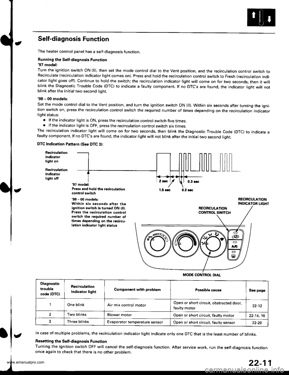
Self-diagnosis Function
The heater control panel has a self-diagnosis function.
Running the Self-diagnosis Function'97 mod€l:
Turn the ignition switch ON {ll), then set the mode control dial to the Vent position, and the recirculation controt switch toRecirculate {recirculation indicator light comes on). Press and hold the recirculation control switch to Fresh (recirculation indi-cator light goes off). Continue to hold the switch; the recirculation indicator light will come on for two seconds. then it willblink the Diagnostic Trouble Code (DTC) to indicate a iaulty component. lf no DTC'S are found, the indicator liqht will notblink atter the initial two second light.
'98 - 00 models:
Set the mode control dial to the Vent position, and turn the ignition switch ON (ll). Within six seconds after turning the igni-tion switch on, press the recirculation control switch the required number of times depending on the recirculation indicatorlight status:
.lftheindicatorlightisON,presstherecirculationcontrol switch five times..lftheindicatorlightisOFF,presstherecirculationcontrol switch six I|mes.The recirculation indicator light will come on for two seconds, then blink the Diagnostic Trouble Code (DTC) to indicate afaulty component. lf no DTC'S are found, the indicator light will not blink after the initial two second liqht.
DTC Indicaiion Pattern {See DTC 3}:
Rocirculationindicatorlight on
Recirculrtionindicatorlighi off'97 model:P.ess and hold th6 recircul.tioncontrol switch'98 - 00 modek:Within six second3 atter theignition switch b turned ON (lll.Prass the rocirculation controlswitch the required number oltimes depending on the r6circu-lation indicator light striu3
,r*
/1.5 aaa 0.3 aac
RECIRCULANONINDICATOR LIGHT
In case of multiple problems, the recirculation indicator light indicate only one DTC that is the least number of blinks.
Resetiing the Solf.diagnosis Funqtion
Turning the ignition switch OFF will cancel the self-diagnosis function. After service work, run the self-diaqnosis functiononce again to check that there is no other Droblem.
MODE CONTROL OIAL
Diagnostic
trouble
code {DTCI
R6circulation
indicator lightComponent with problsmPossiblo causcSee page
'lOne blinkAir mix control molorOpen or short circuit, obstructed door,
faulty motor22-12
2Two blinksElower motorOpen or short circuit, faultv motor22-14,16
Three blinksEvaporator temperature sensorOpon or short circuit, faulty sensor22-20
t
www.emanualpro.com
Page 1102 of 1395
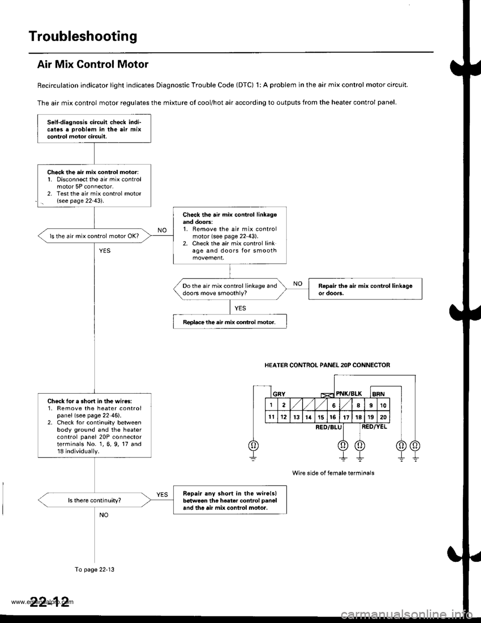
Troubleshooting
Air Mix Control Motor
Recirculation indicator light indicates Diagnostic Trouble Code (DTC) 1: A problem in the air mix control motor circuit.
The air mix control motor regulates the mixture of cool/hot air according to outputs from the heater control panel.
Selt-diagnosis circuit check indi-cates a Droblem in the air mixcontrol motor circuil.
Chock the air mix control moior:1. Disconnect the air mix controlmotor 5P connector,2, Test the air mix control motor(see page 22-43).
Check the air mix control linkagoand doors:1. Remove the air mix controlmotor (see page 22'43).2. Check the air mix control linkage and doors for smooth
ls the air mix control motor OK?
Do the air mix control linkage anddoors move smoothly?
Reolacelhe air mix conlrol motor.
Check Ior a short in the wires:1- Remove the heater controlpanel (see page 22-46).2. Check tor continuity betweenbody ground and the heatercontrol panel 20P connectorterminals No. 1, 6, 9, 17 and18 individually.
Ropair any short in the wire(s)betwoon th. heater co.rtrol panel
and the air mix conlrol motor.
HEATER CONTROL PANEL 2OP CONNECTOR
PNK/BLK
RED/BLU
Wire side of female terminals
To page 22-13
www.emanualpro.com
Page 1103 of 1395
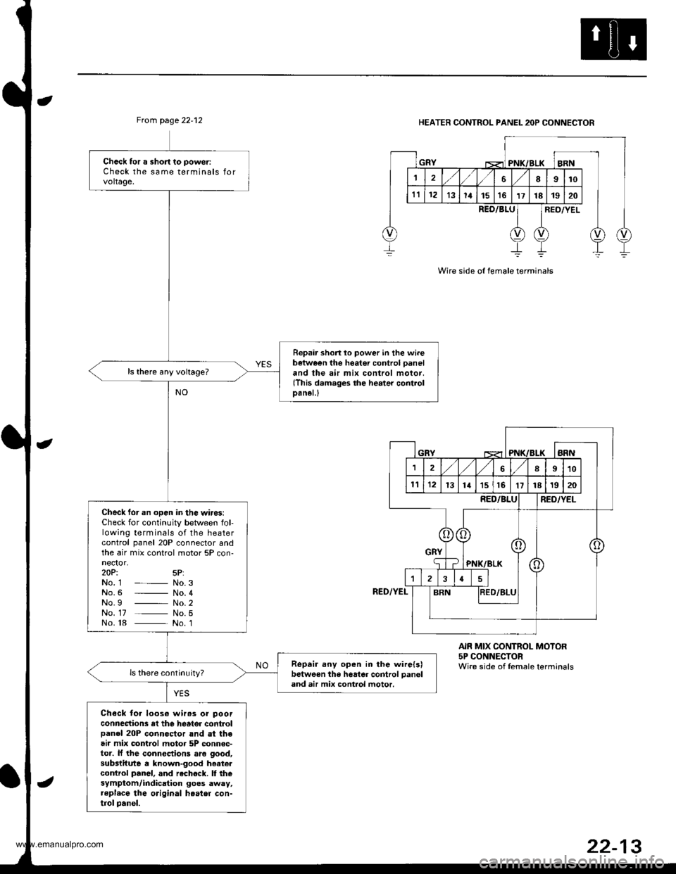
Ftom page 22.12HEATER CONTROL PANEL 2OP CONNECTOR
Wire side ol female terminals
Check tor a short to poweriCheck the same terminals forvoltage.
Repair shon lo power in the wi.ebetween the heater control paneland the air mix control motor,(This damages the heater controlDanel.l
Check tor an open in the wires:Check for continuity between fol-lowing terminals of the heatercontrol panel 20P connector andthe air mix control motor 5P con-nector,zOPi 5P:No. 1 - No.3No.6 _ No. 4No.g _ No.2No. 17 _ No.5No. 18 _ No. 1
Repair any open in the wire{s)betweon the heater control panel
and air mix control motor.
Check toa loos€ wir63 or poorconnections rl the heater controlpanel 20P connector and st theair mix control motor 5P connsc-tor. lJ the connections aro good,substitute a known-good hoatercontrol panel, and rechock. I thesymptom/indication goes away,..pl.ce the original heater con-trol panel.
REO/8LURED/YEL
RED/YEL
AIR MIX CONTROL MOTOR5P CONNECTORWire side of female terminals
www.emanualpro.com