Page 1035 of 1395
Dashboard
Dashboard Removal and Installation (cont'd)
7. Disconnect the connectors and harness cliDS.
>: Boli loc.lionsc>,1a>,5 B>,1
^5\h'.'_. 4fl\',r,' r$\'rmTrr' :j,1.ff,ry-r,.,".\fl)Prtu' W/* W)- tltbt.ttl
c)-
OASHBOARD
CONNECIORS
GUIDE PIN
CONNECTOR
Remove the bolts. then lift and remove the dashboard.
CAUTION: Use protective iape on the botlom of ths tront pillar trim.
lnstallation is the reverse of the removal procedure.
NOTE:
. Make sure the dashboard fits onto the guide pins correctly.
. Before tightening the bolts, make sure the dashboard wire harnesses are not pinched.
. Make sure the connectors and antenna lead are connected properly.
20-54
www.emanualpro.com
Page 1036 of 1395
Dashboard Frame Replacement
CAUTION: Put on gloves to prolect your hands.
NOTE: Take care not to scratch the dashboard and related parts.
GAUGEa: Nut locations,3INSTRUMENTPANEL(see page 20 47)
\,.\
/ ,.-------f,\
lu /A
w
CENTER PANEL{see page 20 50)
6x1.0mm9.8 N.rn 11.0 kgf.m,7.2 tbt.ftl
>i Screw locationsA>,16
I
\,r*
B>,2
^l
S@t' 1-l
c >,2
I
0@l"l
D>.a
^l
0Fl-l
>: Clip localions.2
.dr IIhll'rifi- |-wr
i
DASHBOARDFRAME
DASHBOARDwlRE HARNESS
Installation is the reverse oI the removal orocedure.
NOTE:
. Make sure the dashboard wire harnesses are not Dinched.. Make sure the connectors and antenna lead are connected properly.
FRONT PASSENGER'S
www.emanualpro.com
Page 1055 of 1395
Bumpers
Rear Bumper Removal and Installation
CAUTION: Put on gloves to proteqt your hands.
NOTE:
. An assistant is helpful when removing the rear bumper.. Take care not to scratch the rear bumDer and bodv.
>: Boli, screw locationsa>,2B>,4c>, 10>: Clip locelions, 7
rgfi\\* ffi\\-. 3il;l-'lln*n,..,
WJ/* Y)f t.2tbtftl
.f-.' I
0f'" I trl-l.Kl
-l
BEAR BUMPERSTEP
SIOE MARKERLIGHT CONNECTOFDisconnect.REAR SPLASHGUARD
To body
To body
SIDEMARKERLIGHT
To body
To body
REAR BUMPER
Installation is the reverse of the removal procedure.
NOTE:
. lf necessary, replace any damaged clips.. Make sure the side marker light connectors are plugged in properly.. Make sure the rear bumper engages the side clips on each side securely.
20-74
LIGHT
www.emanualpro.com
Page 1080 of 1395
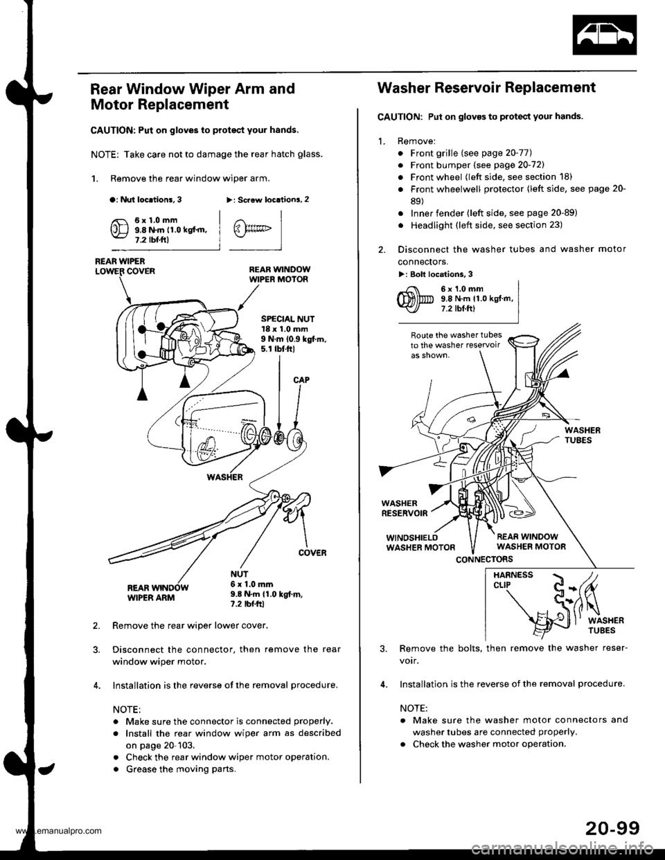
Rear Window Wiper Arm and
Motor Replacement
CAUTION: Put on gloves to protect your hands.
NOTE; Take care not to damage the rear hatch glass.
1. Remove the rear window wiper arm.
a: Nut loc.tion!, 3>: Scaow locationa, 2
REAR WINDOWWIPER MOIOR
REAR WIPERCOVER
REARWIPER ARM
6x1.0mm9.8 N.m 11.0 kgt'm,7.2 tbf.ftl
SPECIAL NUT18 x 1.0 mm9 N.m 10.9 kgt m,5. r tbt.ftl
NUT6x 1.0mm9.8 N.m {1.0 kgt.m,?.2 tbfftl
Remove the rear wiper lower cover.
Disconnect the connector, then remove the rear
window wiper motor.
Installation is the reverse of the removal procedure.
NOTE:
. Make sure the connector is connected properly.
. Install the rea. window wiper arm as described
on page 20-103.
. Check the rear window wiper motor operation.
. Grease the moving parts.
@rrc
Washer Reservoir Replacement
GAUTION: Put on gloves to protect your hands.
1. Remove:
. Front grille (see page 20-771
. Front bumper (see page 20-721
. Front wheel {left side, see section 18)
. Front wheelwell protector (left side, see page 20-
89)
. Inner fender (left side, see page 20-89)
. Headlight (left side, see section 23)
2. Disconnect the washer tubes and washer motor
connectors.
>: Bolt locations, 3
6x1.0mm9,8 N.m 11.0 kgt.m,7.2 tbt.ftl
Route the washer tubesto the washer teservoir
WASHERRESERVOIR
WINOSHIELOWASHER MOTON
CONNECTORS
3. Remove the bolts, then remove the washer reser-
votr,
4. Installation is the reverse of the removal procedure.
NOTE:
a Make sure the washer motor connectors and
washer tubes are connected properly.
. Check the washer motor operation.
HARNESS / tcLrP C-(fu
- S(ilq
s{J
l' wrsHER
20-99
www.emanualpro.com
Page 1100 of 1395
Troubleshooting
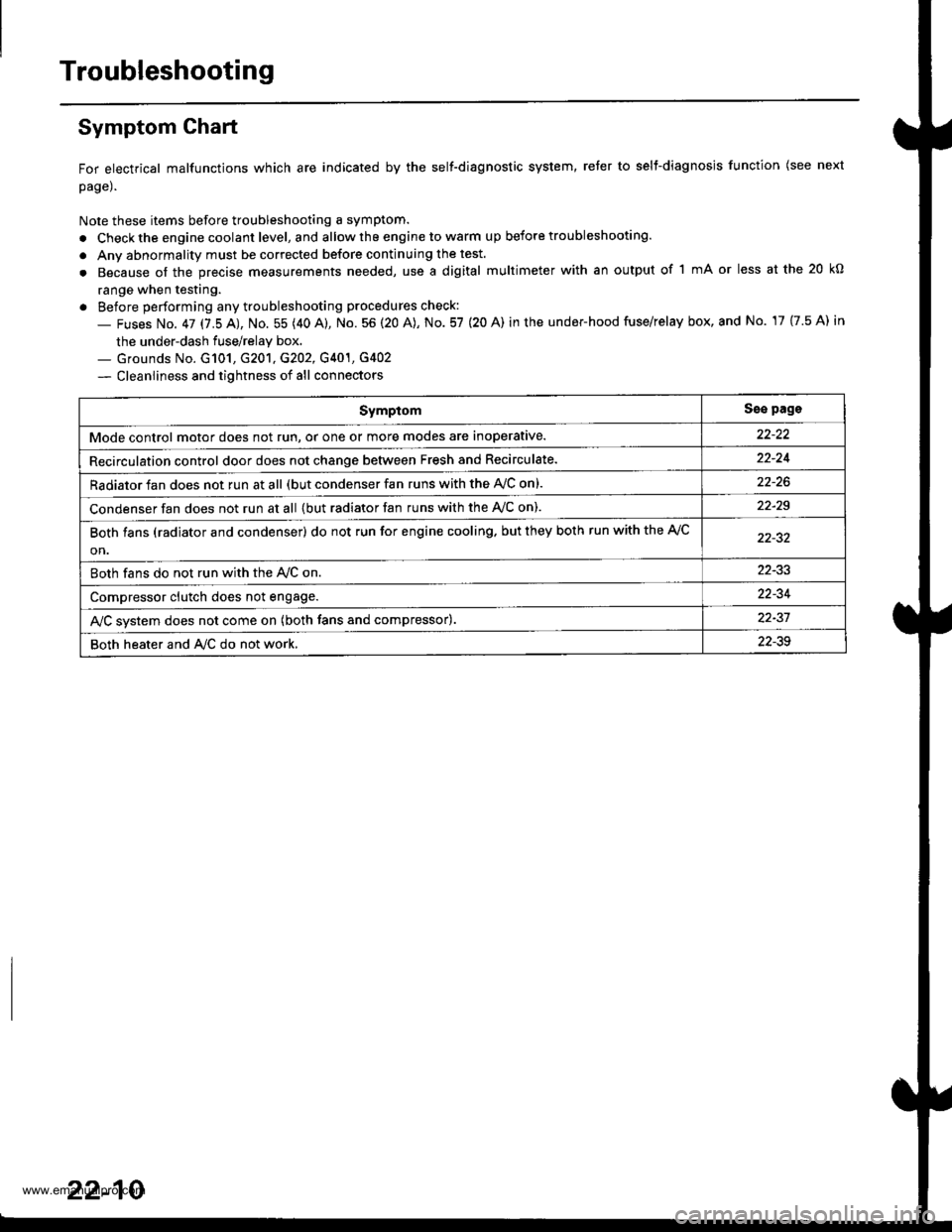
Symptom Ghart
For electrical malfunctions which are indicated by the self-diagnostic system, reter to selt-diagnosjs function (see next
page).
Note these items before troubleshooting a symptom.
. Check the engine coolant level, and allow the engine to warm up before troubleshooting.
. Anv abnormality must be corrected before continuing the test.
. Because of the precise measurements needed, use a digital multimeter with an output of 1 mA or less at the 20 kO
range when testing.
. Before performing any troubleshooting procedures check:
- Fuses No. 47 17.5 AJ, No. 55 (40 A), No. 56 (20 A), No. 57 (20 A) in the under-hood fuse/relay box, and No. 17 {7.5 A) in
the under-dash fuse/relay box.._ Grounds No. G101, G201, G202, G401, G4O2
- Cleanliness and tightness of all connectors
SymptomSse pags
Mode control motor does not run, or one or more modes are inoperative.
Recirculation control door does not change between Fresh and Recirculate.22-24
Radiator fan does not run at all (but condenser fan runs with the AVC on).
Condenser fan does not run at all {but radiator fan runs with the Ay'C on).22-29
Both fans (radiator and condenser) do not run for engine cooling. but they both run with the A,/C
on.
Both fans do not run with the Ay'C on22-33
Compressor clutch does not engage.22-34
AJC svstem does not come on (both fans and compressor).22-37
Both heater and A/C do not work,22-39
22-10
www.emanualpro.com
Page 1105 of 1395
From page 22-14
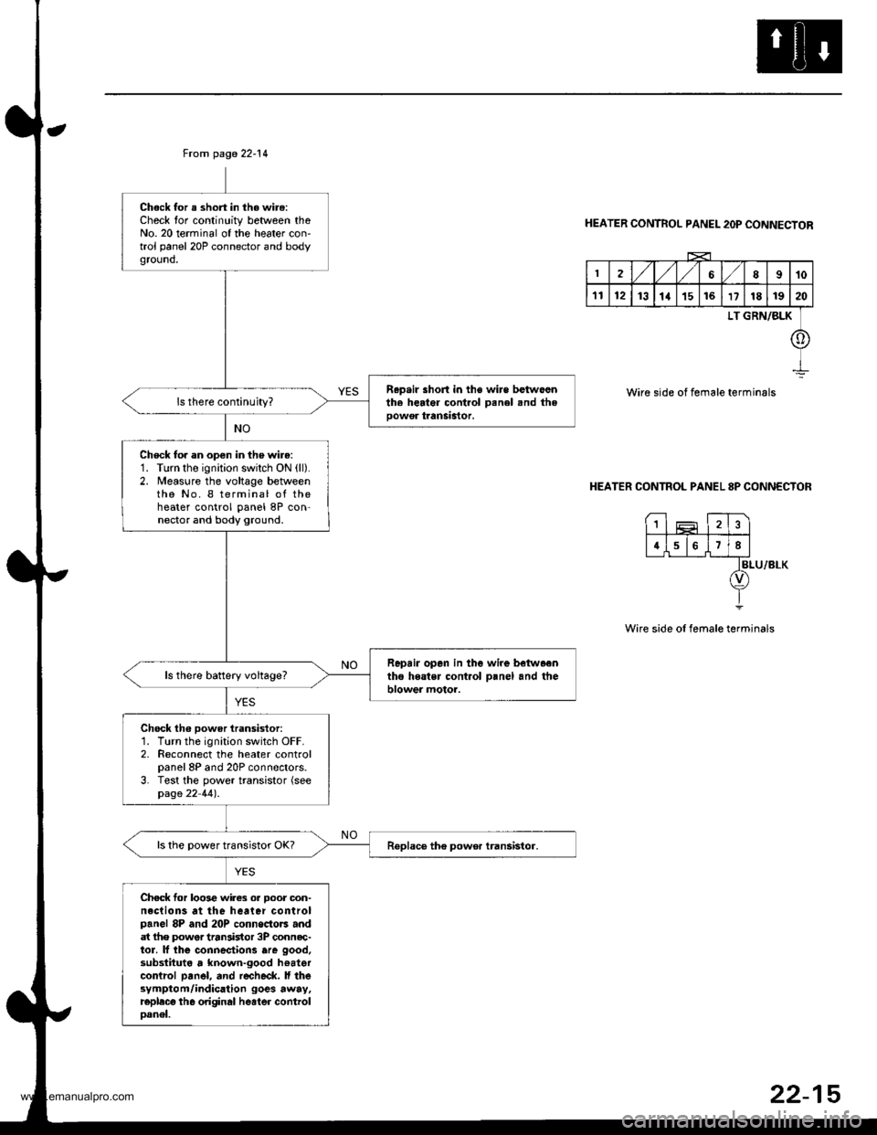
Chock for a short in the wire:Check tor continuity between theNo. 20 terminal of the heater con'trol panel 20P connector and bodyground,
R.p.ir short in the wire betwoenth. herter control Denel snd theoowor tranSastor.
Check to. an open in the wire:1. Turn the ignition swilch ON (ll).
2. Measure the voltage betweenthe No. I terminal of theheater control panel 8P con-nector and body ground.
Repair opan in the wire betwaentho heatsr cont.ol o.nel and theblower motor.ls there battery voltage?
Chock th6 power iransistor:1. Turn the ignition switch OFF.2. Reconnect the heater controlpanel 8P and 20P connectors.3. Test the power transistor (seepage 22 44).
ls the power transistor OK?
Chec* for loo3e wires or Door oon-neclions at the heater controlpanel 8P and 20P connoctors andat lhe power tran3istor 3P connec-tor. lf lhe connectiorc are good,substituta , known-good hoatercontrcl pan6l, and r€check. ll thesymptom/indication goes away.replecg th6 original heater controloanel.
HEATER CONTROL PANEL 2OP CONNECTOR
2,/1,/l/68910
1112131a151617181920
LT GRN/BLK
o
Wire side of female terminals
HEATER CONTROL PANEL 8P CONNECTOR
BLU/8LK
Wire side of female terminals
1
4678
22-15
www.emanualpro.com
Page 1108 of 1395
Troubleshooting
Blower Motor (cont'd)
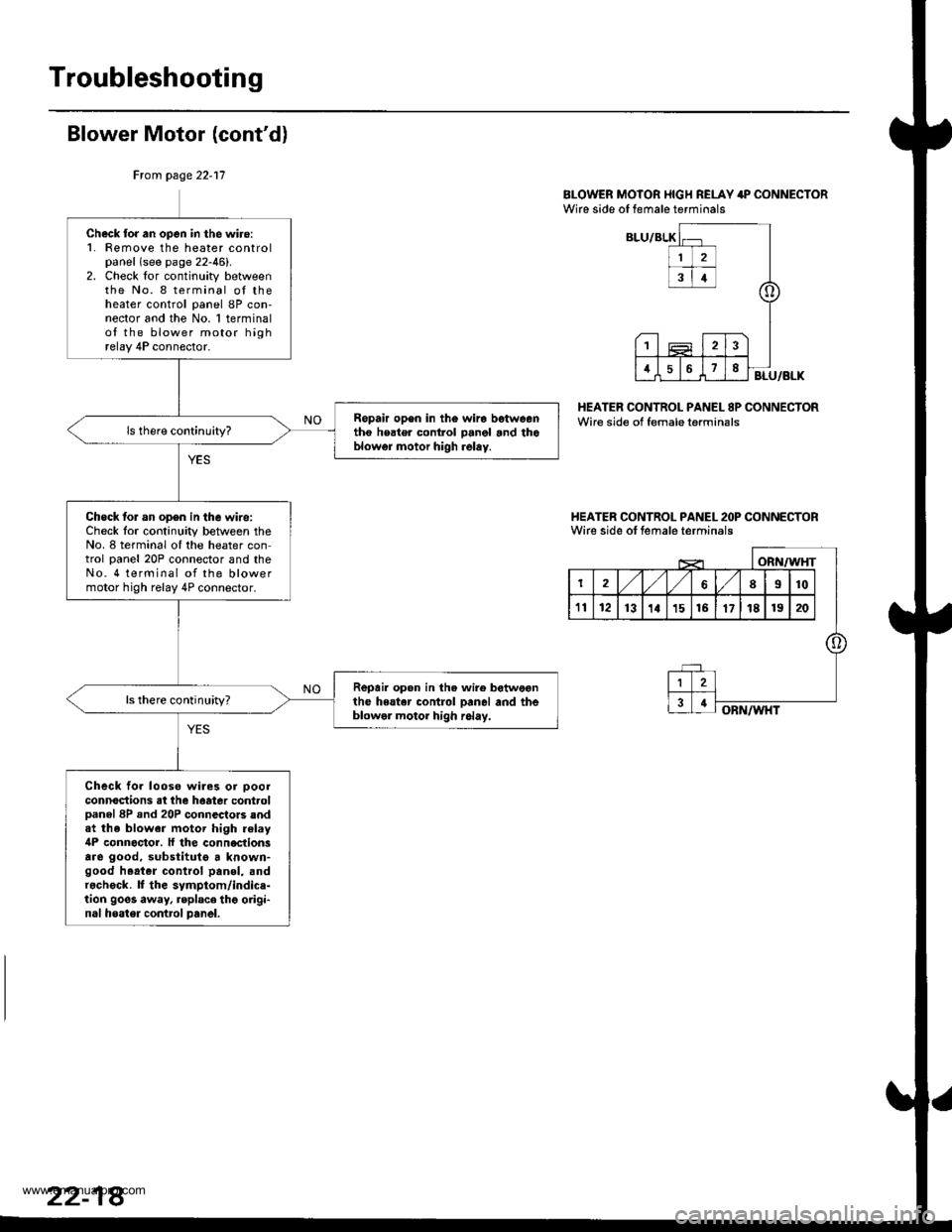
BI-OWER MOTOR I{IGH RELAY 4P CONNECTORWire side of female terminals
HEATER CONTROL PANEL 8P CONNECTORWire side of female terminsls
I{EATER CONTROL PANEL 2OP CONNECTORWirc side ot female terminals
Ftom page 22-17
Check for an open in the wiro:1. Femove the heater controlpanel (see page 22-46).2. Check lor continuity betweenthe No. 8 terminal oI theheater control panel 8P con-nector and the No. 1 terminalof the blower motor highrelay 4P connector.
Ropair op6n in th€ wira betweentho heater control panol and thoblowgr motor high relay.
Check lor an op6n in the wire:Check lor continuity between theNo. 8 terminal oI the heater control panel 20P connector and theNo. 4 terminal of the blowermotor high relay 4P connector.
Repair open in the wire botweonthe heater control Danel and theblowel motor high r6lay.
ls there continuhy?
Check fo. looso wiles or ooolconnoctions at the haatea controlDanel 8P .nd 20P connectors andat the blower motor high relay4P connoctor. ll the conn€ctionsare good, substitutg a known-good h.at.r control panol, andr.check. lf the symptom/indice-tion goes away, replace thg origi-nal heater contrcl panel.
www.emanualpro.com
Page 1126 of 1395
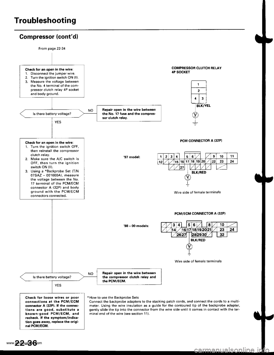
Troubleshooting
Compressor (cont'dl
COMPRESSOR CLUTCH RELAY4P SOCKET
1
2
43
BLK/YEL
PCM CONNECTOB A I32P)
'97 model:
Wire side of female terminals
PCM/ECM CONNECTOR A {32P}
38 - 00 models:
Wire side of {em6le terminals
* How to use the BackDrobe SetsConnect the backprobe adapters to the stacking patch cords, and connect the cords to a multi-meter. Using the wire insulation as a guide for the contoured tip ot the backprobe adapter,gently slide the tip into the connector trom the wire side until it comes in contact with the teFminalend o{the wire {see section l1).
Frcm page 22-34
Ch6ck for an open in the wire:1. Disconnect the jumper wire.2. Turn the ignition switch ON (ll).
3, Measure the voltage betweenthe No. 4 terminal ot the com'pressor clutch relay 4P socketand body ground.
Repair op.n in the wire betweenthe No. l7 fu3e and the compres-sor clutch ielay.
Check for an opon in the wire:1. Turn the ignition switch OFF,then reinstall the compressorclutch relay.2. Make sure the A"/C switch isOFF, then turn the ignitionswitch ON (ll).
3. Using a *Backprobe Set (T/N
07SAZ - 001000A), measurethe voltage between the No.17 terminal ol the PCM/ECMconnector A (32P) and bodyground with the PC M/ECMconnectors connected,
Repair open in lhe wire betwoonthe compressor clutch r6lay andthe PCM/ECM.
Check tor loose wires or Doorconnections at the PCM,/ECMconnecto. A {32P1. lf the connec-tions are good, sub3titute aknown-good PCM/ECM, androcheck. lf the symptom/indica-tion goas away, replac€ the origi-nal PCM/ECM.
126I1011
12151617'181S222321
BLK/RED
22-36
www.emanualpro.com