Page 970 of 1395

DTC 31 - 38: Solenoid
ABS CONTROL UNIT 22P CONNECTOR
Wire sade of female terminals
Wire side of female terminals
ABS CONTROL UNIT 26P CONNECTOR
FL.OUT IYEL/8LKI
DTCAppropraateConnectorTerminal
31: FR'lN22PNo. 1
32: FR OUT22PNo. 12
33: FL lN22PNo. 11
34: FL OUT22PNo.10
35:RR-lN26PNo.13
36: RR-OUT22PNo.21
37: RLIN26PNo.25
38: RL-OUT26PNo. 12
RL.OUT {YELI
FL.OUT IYEL/BLKI
DTCAppropriateTerminal
31: FR lNNo. 2i SCOM
32: FR-OUTNo. 2: SCOM
33: FLINNo.1:PCOM
34: FL-OUTNo. 1:PCOM
35:RRINNo. 1: PCON4
36: RR-OUTNo. 1: PCON4
37rRL-lNNo. 2: SCOM
3a: RL-OUTNo. 2: SCOM
RL.OUT {YELI
- With the ignition switch ON{lD, tho ABS indicator doesnot go off, or the ABS indic.-lor comes on whil6 ABS istunctioning.- With th€ SCS service connoc-tor connoctcd {sce page 1$381,DTCa 31 - 38 ars indicatsd.
Check for a 3hori to power in th€solenoid ci.cuit:1. Disconnect the ABS controluntr tlr ano zbr connectors_2. Start the engine.3. Measure the voltage betweenthe appropriate ABS controlunit connector solenoid circuitterminal and body ground (see
table).
R€pair short to power in theapprop.iato solenoid circuit wirebetwe€n the ABS control unitand the modulator unh.
ls there baRery voltage?
Chock for a short to body groundin the sol€noid circuit:Check for continuity between theappropriate solenoid circuit termi-naland body ground (see table).
. Ropair short to body ground inthe appropriato solenoid circuitwire betwoon the ABS controlunit and the modulator unit.. Replace the modulator unit.
ls there continuity?
Check the ABS control unit:1. Turn the ignition switch OFF.2. Connect the ABS control unit22P and 26P connectors.3. Connect the SCS service con-nector.4. Turn the ignition switch ON (ll).5, Measure the voltage betweenthe appropriate ABS controlunit 26P connector COM circuitterminal and body ground (seetable).
Check tor loose ABS control unitconnectors. ll nece$ary, substi-tut€ a known-good ABS controlunit and recheck.
ls there approx. 3 V7
PCOM
(To page l9-48){GRN/WHTI
19-47
www.emanualpro.com
Page 972 of 1395

DTC 51 - 53: ABS Pump Motor
NOTE: Short the PMR terminal to bodyground for a moment, and rochock the tuse.lf the fuse is blown, check lor a shon to bodyground in the MCK circuit.
NOTE: Short the PMR terminal to bodyground for a moment, and recheck the fuse,lf the tuse is blown, check tor a short to bodyground in the wire between the under hoodABS fuse/relay box 6nd the pump motor.
ABS CONTROL UNIT 22P CONNECTOR
Wire side of female terminals
(cont'di
- Wilh the ignition switch ON{ll), the ABS indicator doesnot go ott.- With the SCS seruico connec-tor connoctod {sce page 19381,DTCa 51 - 53 .re indicated.
check the MTR cHEcK (7.5 Ailuse in the under-hood ABStuse/relay box, and reinstall theluse if it is OK.
Rsplace the fuse and rech6ck.
check the PUMP MOTOR (40 A)fuse in the under-hood ABS fuse/relay box, and reinstall the fuse ifit is oK.
Roolace lhe tusg and rocheck.
Feplace the pump motor r6ley.
Check the pump motor powelsourc€ circuit:Turn the ignition switch ON (ll).
Ch6ck fo. a short to oowd in th6pump motor power sourca circuit:Remove the pump motor relay.Does the pump motor operate?
Repair rhort to power in the wirebclweon the under-hood ABSfuse/.6lay box and ihe ABSpump motor.
Does the pump motor operateT
Ch6ck tor loos6 ABS control unitconnectors. lf necotsary, 3ubsti-tute . known-good ABS controlunit and rocheck.
(To page 19 50)
19-49
www.emanualpro.com
Page 979 of 1395

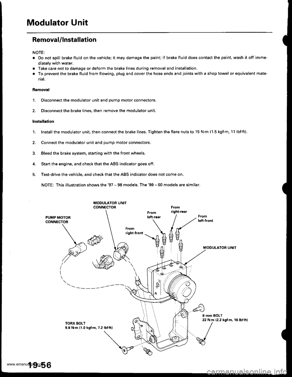
Modulator Unit
Removal/lnstallation
NOTE:
. Do not spill brake fluid on the vehicle; it may damage the painu if brake fluid does contact the paint, wash it off imme-
diately with water.
a Take care not to damage or deform the brake lines during removal and installation.
. To prevent the brakefluidfrom flowing, plug and coverthe hose ends and joints with a shop towel or equivalent mate-
rial,
Romoval
1. Disconnect the modulator unit and Dump motor connectors.
2. Disconnect the brake lines, then remove the modulator unit.
lnstallation
1. Install the modu lator u nit. then con nect the brake lines. Tighten the flare nuts to 15 N.m ( 1.5 kgf.m, 1 1 lbf.ft).
2. Connect the modulator unit and oumo motor connectors.
3. Bleed the brake system, staning with the front wheels.
4. Start the engine, and check that the ABS indicator goes off.
5. Test-drive the vehicle, and check that the ABS indicator does not come on,
NOTE: This illustration shows the '97 - 98 models. The'99 - 00 models are similar.
PUMP MOTORCONNECTOR
MODULATON UNIT\*\
,@
I
TORX EOLT9.8 N,m (1.0 kgf.m.7.2lbf ftl
19-56
www.emanualpro.com
Page 980 of 1395
ABS Control Unit
Pulsers/Wheel
Sensors
Replacement
Remove the passenger's side kick panel.
Disconnect the ABS control unit connectors.
Remove the ABS control unit.
Install the ABS control unit in the reverse order ofremovat.
ABS CONTROL UNIT
CONNECTORS
L
Inspection
1.Check the front and rear pulser for chipped or dam-
aged teeth.
Measure the air gap between the wheel sensor andpulser all the way around while rotating the pulser.
lf the gap exceeds 1.0 mm (0.04 in), check for a bentsusDension arm.
Standard: o.il - 1.0 mm 10.02 - 0.04 inl
Front/Rear
Remove the rear brake drum to insDect the rear wheolsensor air gap,
0.4 - 1.0 mm(0.02 - 0.04 inl
19-57
www.emanualpro.com
Page 1023 of 1395
Interior Trim
@wt we@M
REAR SIOETRIM PANELRemove the reat seat(see page 20-63).
FCONNECTOR
2
OUARTER PILLARTNIM PANELRemove the rear hatch glasssupport strut (see page20-741.
Removal and Installation (cont'd)
>i Clip loc.tionsa>,21B>,4c>, 1E>. !F >,3D>, 1
Disconnect the accessorysocket connectors,
9.8 N.m (1.0 kgf.m,1.2lbt-lrl
5x1.0mm6x1.0mm9.8 N.m (1.0 kgtm,7.2 tbf ftl
TIE DOWNHOOK
6x1.0mm
TIEoowNHOOK
v
O\A
D
REAR SEAT BELTLOWER ANCHOR EOLT7/16 - 20 UNF32 N.m {3.3 kgt.m,24 tbl.frl
9.8 N.m (1.0 kgt m,7.2 tbf.ft)
REAR TRIM PANELRemove the cargo area floorand cargo slorage bin.
20-42
REAN SEAT BELTUPPER ANCHOR BOLT7/16-20 UNF32 N.m {3.3 kgt.m,24 rbt.ft)
REAR DOOR
REAR
ffi
STRIKER
www.emanualpro.com
Page 1031 of 1395

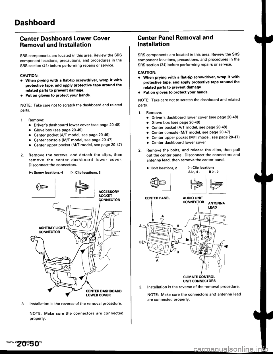
Dashboard
Center Dashboard Lower Gover
Removal and Installation
SRS components are located in this area. Review the SRS
component locations, precautions, and procedures in the
SRS section {24) before performing repairs or service
CAUTION:
. Wh€n prying with a flat-tip screwdrivet, wrap it with
protective tap€, and apply proteclive tape around the
rslated parts to prevenl damage.
. Put on glovgs to protect your hands.
NOTE: Take care not to scratch the dashboard and related
oarts.
1. Remove:
. Driver's dashboard lower cover (see page 20-48)
. Glove box (see page 20-49)
. Center pocket (AVT model. see page 20-49)
. Center console (M/f model, see page 20-41l,
. Center upper pocket (M/T model, see page 2O-47J
2. Remove the screws, and detach the clips. then
remove the center dashboard lower cover.
Disconnect the connectors.
>: Screw locationa,.a
I
6br" I-l
3. Installation is the reverse of the removal procedure-
NOTE: Make sure the connectors are connected
properly.
20-50
>: Clip loc.tion6,3
I5
\"P I AccEssoRyI socKET
Center Panel Removal and
lnstallation
SRS components are located in this area. Review the SRS
comDonent locations, precautions, and procedures in the
SRS section (24) before performing repairs or servace.
CAUTION:
. When prying with a flat-tip screwdriver, wrap it with
protective tape, and apply protective tape around the
relatgd parts to prevent damage.
. Put on gloves to protect your hands.
NOTE: Take care not to scratch the dashboard and related
parts.
1. Remove:
. Driver's dashboard lower cover (see page 20-48)
. Glove box (see page 20-49)
. Center pocket (A,/T model, see page 20-49)
. Center console (M/T model, see page 20-47)
. Center upper pocket {M/T model, see page 20-47)
. Center dashboard lower cover
2. Remove the bolts, and release the clips. then pull
out the center panel. Disconnect the connectors and
antenna lead. then remove the center panel.
CLIMATE CONTBOLUNIT CONNECTORS
3. Installation is the reverse of the removal procedure.
NOTE: Make sure the connectors and antenna lead
are connected proPerly.
>: Clip location3A >,4 B>,2
tt.t !^ t u . I\lJS>,, \>ryI is I r-,/'
AUOIO UNIT
>: Bolt locations,2
(8NED L-l
CENTER PANEL
www.emanualpro.com
Page 1032 of 1395

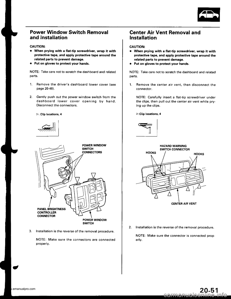
Power Window Switch Removal
and Installation
CAUTION:
. When prying with a flat.tip screwdriver, wrap it withprotective tape, and apply protective tape around th€
related parts to ptavgnt damage.
. Put on gloves to protect your hands.
NOTE: Take care not to scratch the dashboard and relatedparts.
'L Remove the driver's dashboard lower cover (see
page 20-48).
2. Gently push out the power window switch from the
dashboard lower cover opening by hand.
Disconnect the connectors.
>: Clip locations, 4
POWER WTNOOWSWITCH
Installation is the reverse of the removal procedure,
NOTE: Make sure the connectors are connectedproperly.
Center Air Vent Removal and
Installation
CAUTION:
. When prying with a flat.tip screwdriver, wrap h withprotective tape, and apply proteqtive tape around the
rolated parts to prevont damage.
. Put on gloves to protect your hands.
NOTE: Take care not to scratch the dashboard and related
pans.
1. Remove the center air vent. then disconnect the
connector.
NOTE: Carefullv insen a flat-tio screwdriver under
the clips, then pull out the center air vent while pry-
ing up the clips.
Installation is the reverse of the removal procedure.
NOTE; Make sure the connector is connected prop-
>:Clip locations.,l
I
ffil
CENTER AIB VENT
20-51
www.emanualpro.com
Page 1034 of 1395

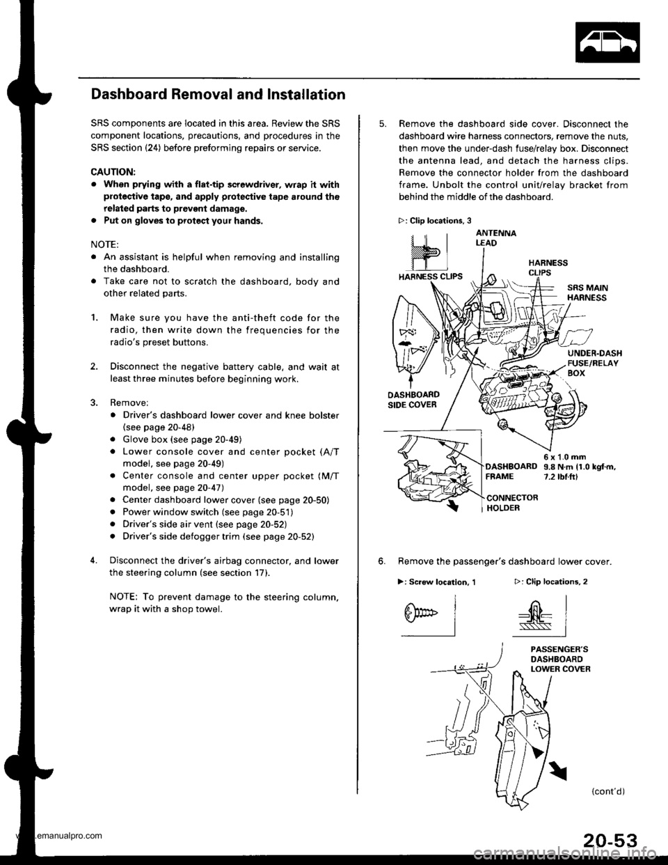
Dashboard Removal and Installation
SRS components are located in this area. Review the SRS
component locations, precautions, and procedures in the
SRS section {24) before preforming repairs or service.
CAUTION:
. When prying with a flat-tip screwdriver, wrap h withprotective tap€, and apply protective tape around the
related parts to prevgnt damage.
. Put on gloves to prot€ct your hands.
NOTE:
. An assistant is helpful when removing and installing
the dashboard.
. Take care not to scratch the dashboard, bodv and
other related parts.
1.Make sure you have the anti-theft code for the
radio, then write down the frequencies for the
radio's preset buttons.
Disconnect the negative battery cable. and wait at
least three minutes before beginning work.
Removei
a Driver's dashboard lower cover and knee bolster(see page 20-48)
. Glove box (see page 20-49)
. Lower console cover and center pocket (A/T
model, see page 20-49)
. Center console and center upper pocket (M/T
model, see page 20-47)
. Center dashboard lower cover (see page 20-50)
. Power window switch (see page 20-51)
. Driver's side air vent (see page 20-52)
. Driver's side defogger trim (see page 20-52)
Disconnect the driver's airbag connector, and lower
the steering column (see section 17)
NOTE: To prevent damage to the steering column,
wrap it with a shop towel.
2.
5. Remove the dashboard side cover. Disconnect the
dashboard wire harness connectors, remove the nuts,
then move the under-dash fuse/relay box. Disconnect
the antenna lead, and detach the harness clips.
Remove the connector holder from the dashboard
frame. Unbolt the control unit/relay bracket from
behind the middle of the dashboard.
HARNESS
6. Remove the passenger's dashboard lower cover.
D: Clip locations,
nl
-$t- Issj
I
ANTENNALEAD
>: Clip locations.
rttl
slllll
>: Scr€w location, 1
I
SF:oo I-l
SRS MAINHARNESS
UNDER.DASHFUSE/RELAYBOX
OASHBOARDSIDE COVER
6x1.0mm9.8Nm11.0kgf.m,7.2tbt.ftlDASHBOARDFFAME
CONNECTORHOLDER
PASSENGER'SDASHBOARDLOWER COVER
{cont'd)
www.emanualpro.com