2000 HONDA CR-V tow
[x] Cancel search: towPage 3 of 1395
General lnformation
Chassis and Paint Codes ....................... 1-2
ldentification Number Locations ......... 1-10
Warning/Caution Label Locations ....... 1-11
Under-hood Emissions Control
Label .......... ..................... 1-15
Lift and Support Points
Lift and Safety Stands ....................... 1-19
Floor Jack ....................... 1-20
Towing .........1-21
Service Precautions
Pafts Marking Locations ..,................. 1-22
Precautions for Real-time 4WD
(Four-wheel Drivel ......... ................. 1 -23
www.emanualpro.com
Page 23 of 1395
Towing
lf the vehicle needs to be towed, call a professional
towing service. Never tow the vehicle behind another
vehjcle with just a rope or chain. lt is very dangerous.
Emergency Towing
There are three popular methods of towing a vehicle.
Flat-bed Equipment - The operator loads the vehicle on
the back of a truck. This is the best way of transporting the
vehicle.
Wheel Lift Equipment - The tow truck uses tlvo pivoting
arms that go under the tires lfront or rear) and lifts them
off the ground. The other two tires remain on the
ground. The vehicle's suspension and body can be
seriously damaged if this method of towing is attempted.
Sling-type Equipment - The tow truck uses metal cables
with hooks on the ends. These hooks go around parts of
the frame or suspension and the cables lift that end of
the vehicle off the ground. The vehicle's suspension and
body can be seriously damaged if thjs method of towing
is attempted. This methed of towing the CR-V is
unaccePtable.
The onlv recommended way of towing the CR-V is on a
flat-bed truck. Two wheel drive CR-V's may also be
towed with all four wheels on the ground.
Towing the four-wheel dlive CR-v with only two
wheels on the ground will damage parts of the 4wD
system. It this vehicle is damaged, it should be towed
on a flat-bed truck ol trailel.
It the 2 wheel drive CR-v is towed wiih all tour wheels
on the ground, do the following:
Manual Transmission
. Release the parking brake.
. Shift the transmission in Neutral
Automatic Transmission
. Release the parking brake.
. Sta rt the engine.
. Shift to lD.l position. then E position.
. Turn off the engine.
lmproper towing preparation will damage the
transmission. Follow the above procedure exactly. lf
you cannot shift the transmission or start the engine,
the vehicle must be transported on a flat-bed truck.
lf the vchicle is towed with four wheels on the ground,
il is best to tow the vehicle no larther than 50 miles (80
km), and keep the speed below 35 mph {55 km/h).
Trying to lift or tow the vehicle by ihe bumpers will
cause serious damage. The bumpers ale not dosigned
to support the vehicle's weight.
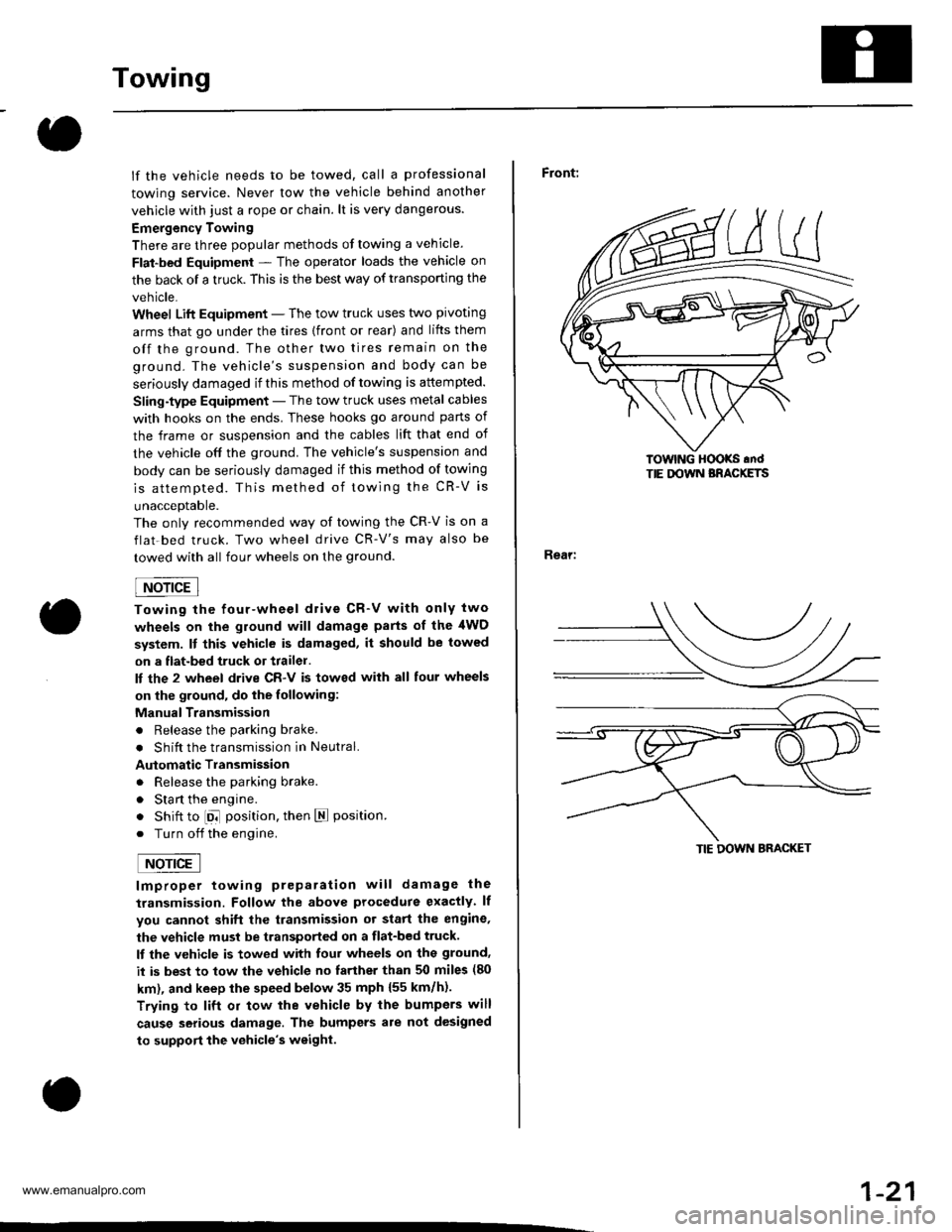
Front:
Rear:
lOwlNG HOOKS .ndTIE DOWN BRACKETS
TIE DOWN BRACKET
1-21
www.emanualpro.com
Page 66 of 1395

lgnition System
5.
lgnition Timing Inspection and Setting
2.
1.Check the idle speed, and adjust it if necessary (see
section 1 1).
Pull out the service check connector 2P (BRN and
BLK wires) from the connector holder located under
the dash on the front passenger side, then connect
the scs service connector (P/N 07PAz - 0010100) to
it.
Start the engine. Hold the engine at 3,000 rpm with
no load (A/T in N or E, Mff in neutral) until the
radiator fan comes on, then let it idle.
Connect the timing light to the No. I ignition wire,
then point the light toward the pointer on the timing
belt cover.
Check the ignition timing in no load conditions:
headlights, blower fan, rear window defogger, and
air conditioner are not operating.
lgnition Timing:
M/T: 16" 12" BTDC (RED) idling in neutral
AlTt'16" !2" BTDC (RED) idling in E or E
CRANKSHAFTPULLEY
4-16
6. lf necessary, adjust the ignition timing as follows.
Loosen the distributor mounting bolts, and turn the
distributor ignition (Dl) housing counterclockwise to
advance the timing or clockwise to retard the tim-
t no,
7.
8.
MOUNTING BOLTS24 N.m {2.4 kgf m, 17 lbtft}
Tighten the distributor mounting bolts, and recheck
the ignition timing.
Disconnect the SCS service connector from the ser-
vice check connector.
To RETARD
www.emanualpro.com
Page 118 of 1395
Valve Seals
Replacement (cylinder head removal not required)
The procedure shown below applies when using the in-
car valve spring compressor (Snap-on YA8845 with
YA8845-2A 7/8" auachment). Use approved eye protec-
tion.
1. Turn the crankshaft so that the No. 1 and the No. 4
pistons are at top dead center (TDC).
2. Remove the cylinder head cover.
3. Remove the distributor.
4. Loosen and disconnect the timing belt from the
camshaft pulleys.
5. Remove the camshaft holder bolts. then remove the
camshaft holders, the camshafts and rocker arms.
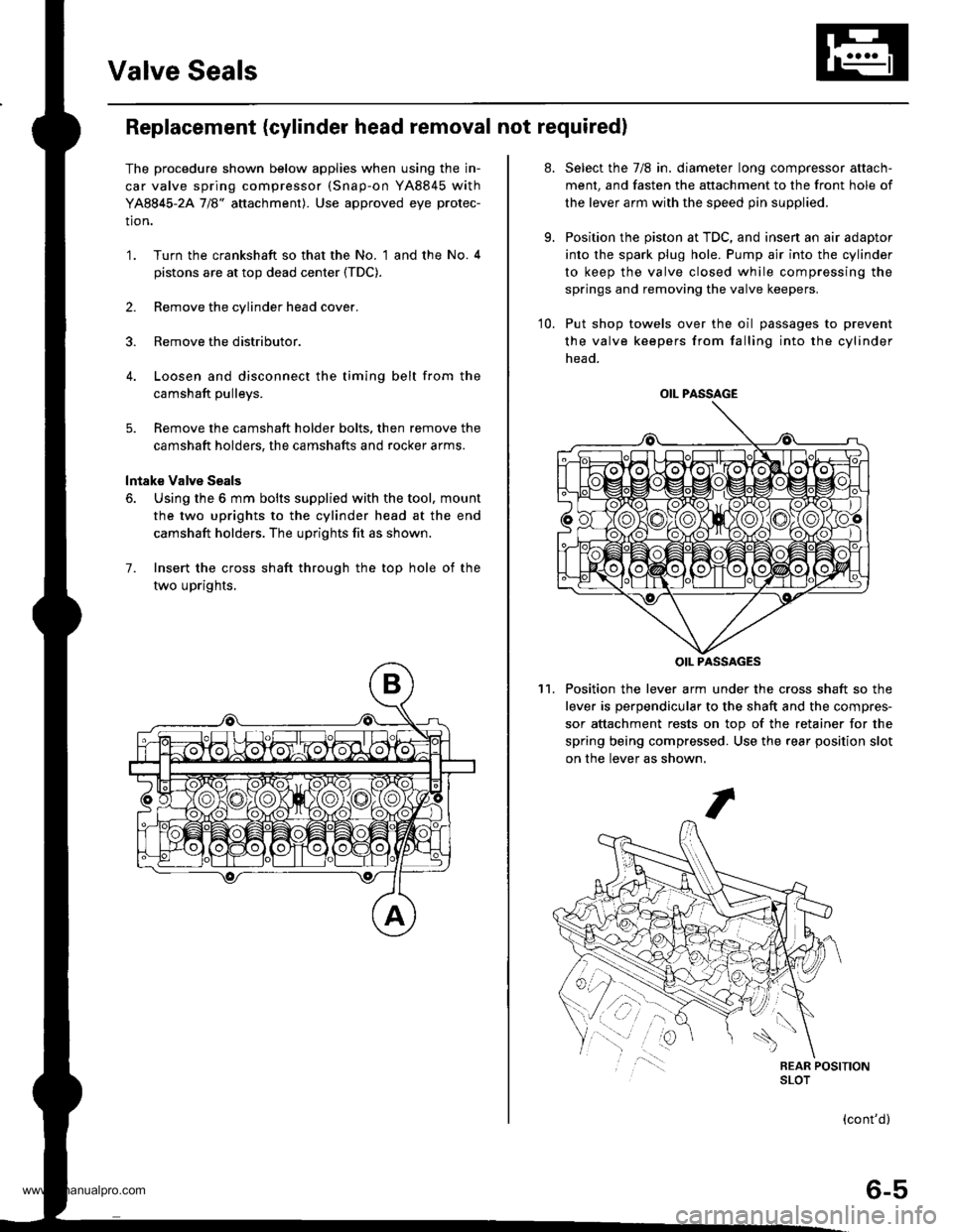
lntake Valve Seals
6. Using the 6 mm bolts supplied with the tool, mount
the two uprights to the cylinder head at the end
camshaft holders. The uprights fit as shown.
7. Insert the cross shaft through the top hole of the
two uprights,
at.
9.
Select the 7/8 in. diameter long compressor attach-
ment, and fasten the attachment to the front hole of
the lever arm with the speed pin supplied.
Position the piston at TDC, and insen an air adaptor
into the spark plug hole. Pump air into the cylinder
to keep the valve closed while compressing the
springs and removing the valve keepers.
10. Put shop towels over the oil passages to prevent
the valve keepers from falling into the cylinder
head.
Position the lever arm under the cross shaft so the
lever is perpendicular to the shaft and the compres-
sor attachment rests on top of the retainer for the
spring being compressed. Use the rear position slot
on the lever as shown,
't1.
OIL PASSAGE
OIL PASSAGES
(cont'd)
6-5
www.emanualpro.com
Page 119 of 1395
Valve Seals
12.
Replacement (cylinder head removal not requiredl (cont'dl
Using an upward motion on the lever arm, compress
the valve spring and remove the keepers from the
valve stem. Slowly release pressure on the spring.
Repeat step 11 for the other valve in that cylinder.
Remove the valve seals (see page 6-24).
Installthe valve seals (see page 6-29).
lnstall the springs, the retainers and the keepers in
reverse order of removal.
'17. Repeat steps 9 to 16 for the other three cylinders.
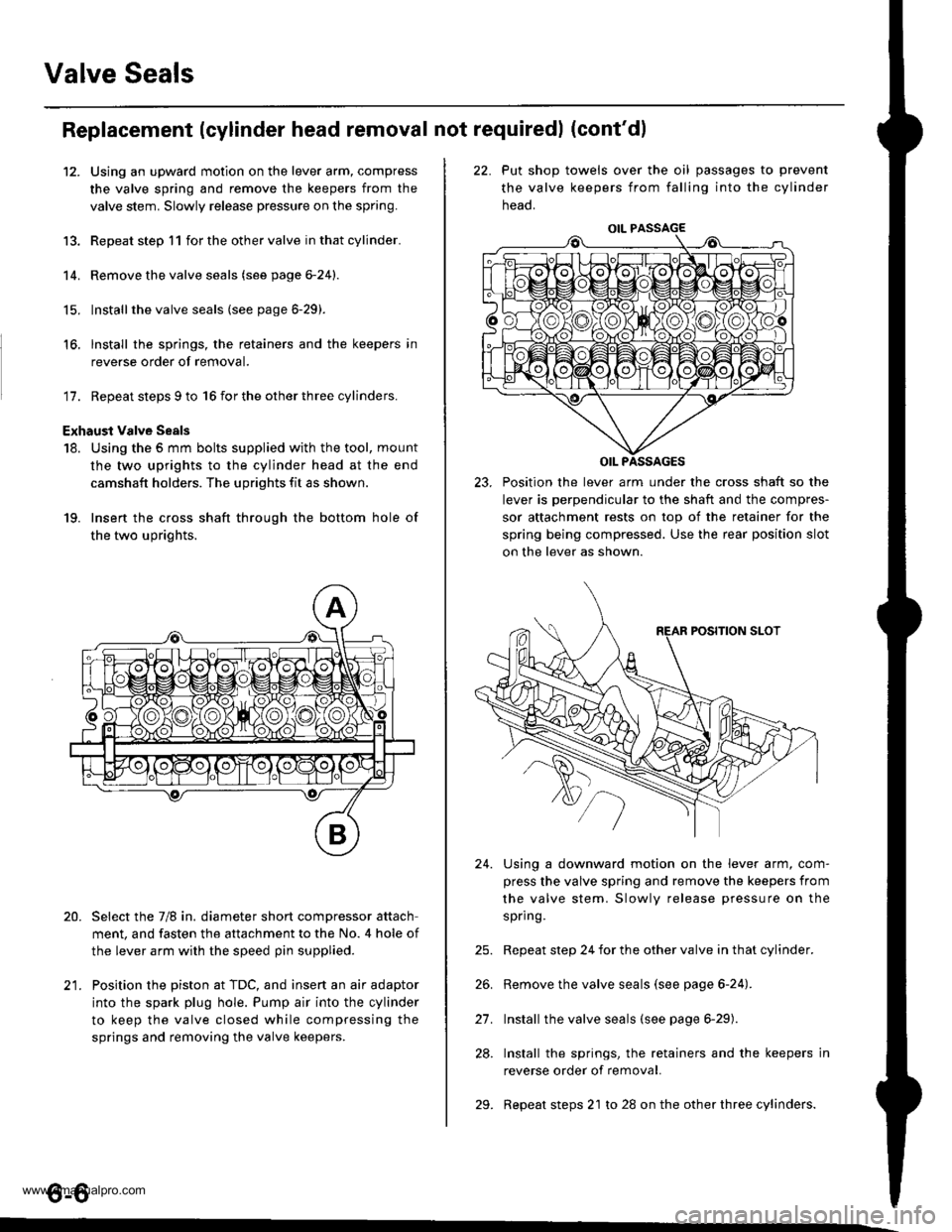
Exhaust valve Seals
18. Using the 5 mm bolts supplied with the tool, mount
the two uprights to the cylinder head at the end
camshaft holders. The uprights fit as shown.
19. Insert the cross shaft through the bottom hole of
the two uprights.
Select the 7/8 in. diameter short compressor attach
ment, and fasten the attachment to the No. 4 hole of
the lever arm with the speed pin supplied.
Position the piston at TDC, and insert an air adaptor
into the spark plug hole. Pump air into the cylinder
to keep the valve closed while compressing the
springs and removing the valve keepers.
13.
14.
15.
16.
20.
t1
22. Put shop towels over the oil passages to prevent
the valve keepers from falling into the cylinder
neao.
23. Position the lever arm under the cross shaft so the
lever is perpendicular to the shaft and the compres-
sor attachment rests on top of the retainer for the
spring being compressed. Use the rear position slot
on the lever as shown.
Using a downward motion on the lever arm, com-
press the valve spring and remove the keepers from
the valve stem. Slowly release pressure on the
spring.
Repeat step 24 for the other valve in that cylinder.
Remove the valve seals (see page 6-24).
Install the valve seals (see page 6-29).
Install the springs, the retainers and the keepers in
reverse order of removal.
Repeat steps 21 to 28 on the other three cylinders.
24.
21.
28.
29.
o-o
www.emanualpro.com
Page 135 of 1395
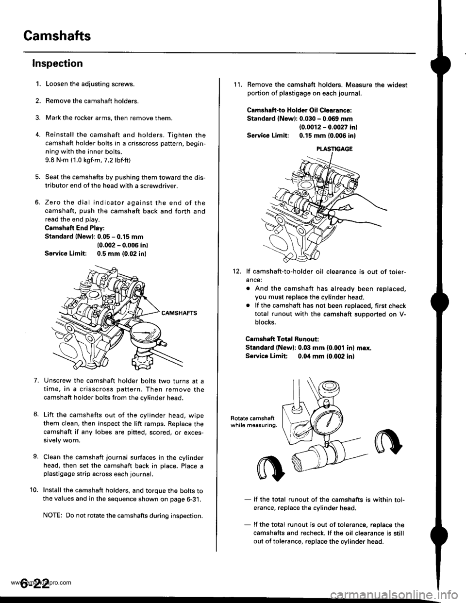
Camshafts
4.
Inspection
1.
7.
Loosen the adjusting screws.
Remove the camshaft holders.
Mark the rocker arms, then remove them.
Reinstall the camshaft and holders. Tighten the
camshaft holder bolts in a crisscross pattern, begin-
ning with the inner bolts.
9.8 N.m (1.0 kgf.m.7.2 lbf.ft)
Seat the camshafts by pushing them toward the dis-
tributor end of the head with a screwdriver.
Zero the dial indicator against the end of the
camshaft, push the camshaft back and forth and
read the end play.
Camshaft End Play:
Standard lNewl: 0.05 - 0.15 mm
10.002 - 0.005 in)
Service Limit: 0.5 mm (0.02 in)
Unscrew the camshaft holder bolts two turns at a
time, in a crisscross pattern, Then remove the
camshaft holder bolts from the cvlinder head.
Lift the camshafts out of the cylinder head. wipe
them clean, then inspect the lift ramps, Replace the
camshaft if any lobes are pitted, scored, or exces-
sively worn.
Clean the camshaft journal surfaces in the cylinder
head, then set the camshaft back in Dlace. Place aplastigage strip across each journal.
Install the camshaft holders. and torque the bolts tothe values and in the sequence shown on page 6-31.
NOTE: Do not rotate the camshafts during inspection.
8.
10.
6-22
11. Remove the camshaft holders. Measure the widest
portion of plastigage on each journal.
Camshatt-to HoldGr Oil Clearance:
Standard {Newl: 0.030 - 0.069 mm
{0.0012 - 0.0027 in}
Servico Limit: 0.15 mm (0.006 in)
12. lf camshaft-to-holder oil clearance is out of toler-
ance:
. And the camshaft has already been replaced,
you must replace the cylinder head.. lf the camshaft has not been replaced, first check
total runout with the camshaft suoDorted on V-
blocks.
Camshaft Total Runout:
Standard (N6w): 0.03 mm (0.001 in) max.
Service Limit 0.04 mm (0.(X)2 in)
Rotat6 camshattwhile measuring.
- lf the total runout of the camshafts is within tol-
erance, replace the cylinder head
- lf the total runout is out of tolerance, replace the
camshafts and recheck. lf the oil clearance is still
out of tolerance, replace the cylinder head.
www.emanualpro.com
Page 139 of 1395
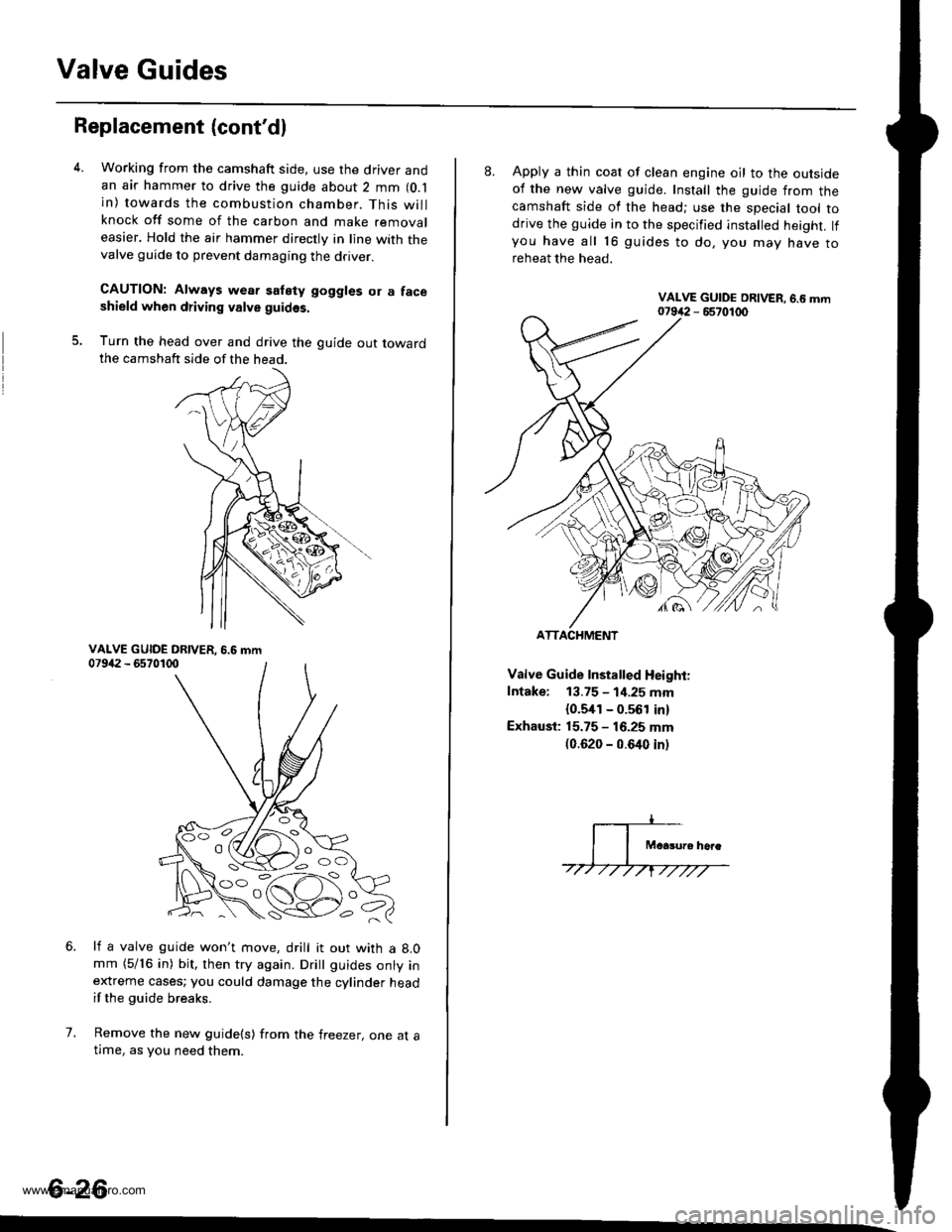
Valve Guides
Replacement (cont'dl
5.
Working from the camshaft side, use the driver andan air hammer to drive the guide about 2 mm (O.l
in) towards the combustion chamber. This willknock off some of the carbon and make removaleasier. Hold the air hammer directly in line with thevalve guide to prevent damaging the driver.
CAUTION: Always wear satety goggles or a faceshield when driving valve guidss.
Turn the head over and drive the guide out towardthe camshaft side of the head.
li a valve guide won't move, drill it out with a 8.0mm (5/16 in) bit, then try again. Dritt guides onty inextreme cases; you could damage the cylinder headif the guide breaks.
Remove the new guide(s) from the freezer, one at atlme, as you need them.
6.
7.
6-26
'o C'
8. Apply a thin coat of clean engine oil to the outsideof the new valve guide. Install the guide from thecamshaft side of the head; use the special tool todrive the guide in to the specified installed height. lfyou have all 16 guides to do, you mav have toreheat the head.
Valve Guide Installed Height:
Intake: 13.75 - 1i1.25 mm
{0.5,[1 - 0.561 in)
Exhaust: 15.75 - 16.25 mm(0.620 - 0.640 inl
ATTACHMENT
www.emanualpro.com
Page 142 of 1395
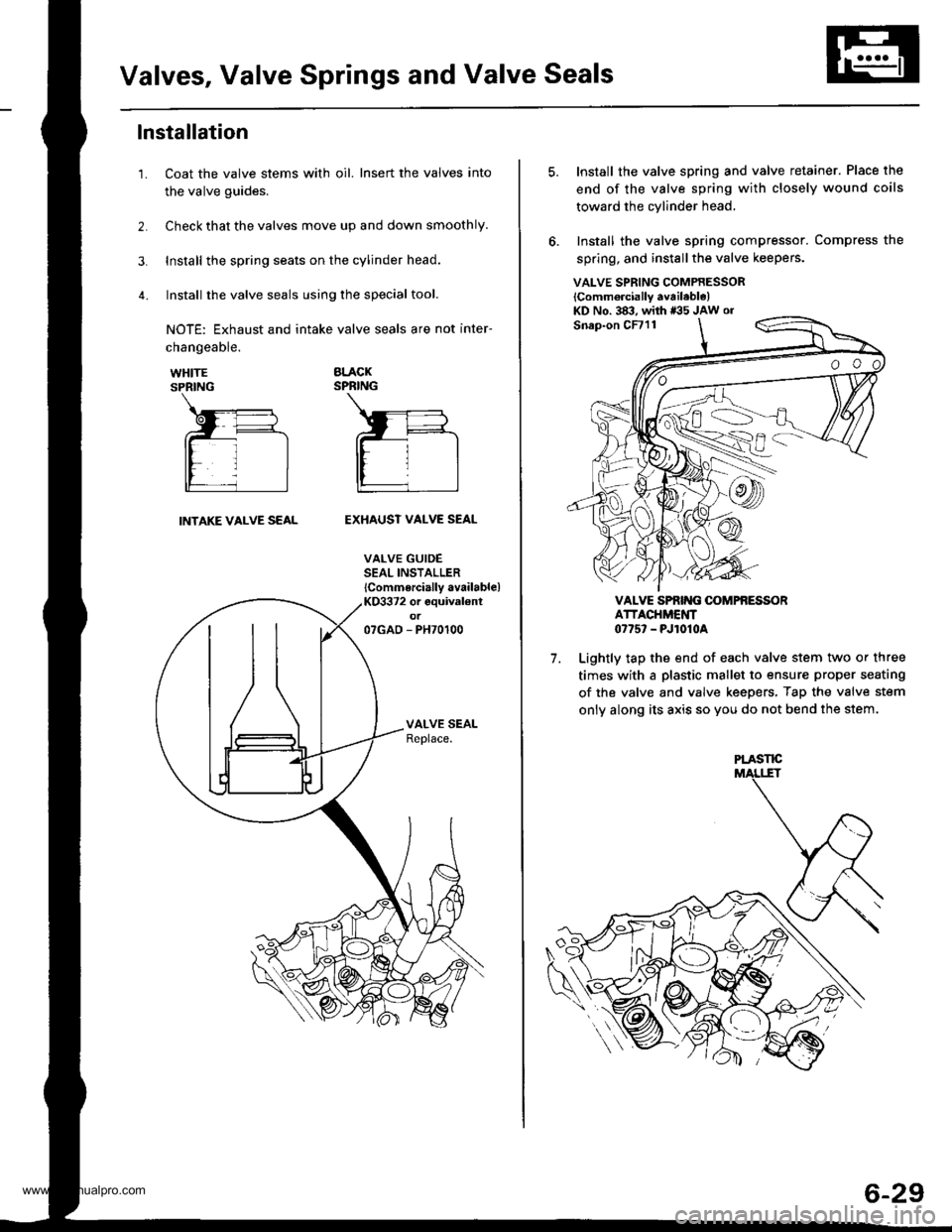
Valves, Valve Springs and Valve Seals
lnstallation
Coat the valve stems with oil. Insert the valves into
the valve guides.
Check that the valves move up and down smoothly.
Install the spring seats on the cylinder head.
Install the valve seals using the special tool.
NOTE: Exhaust and intake valve seals are not inter-
1.
changeable.
WHITESPRING
BLACKSPRING
INTAKE VALVE SEALEXHAUST VALVE SEAL
VALVE GUIDESEAL INSTALLER
lCommercially available)KO3372 or equival€ntot07GAD - PH70100
VALVE SPRING COMPRESSOR
lComm6rcially available)KD No. 383, with *35 JAw or
7.
Install the valve spring and valve retainer. Place the
end of the valve spring with closely wound coils
toward the cylinder head,
Install the valve spring compressor. Compress the
spring, and install the valve keepers.
VALVE SPRIT{G OOMPfi ESSORATTACHMENT0775' - PJ1010A
Lightly tap the end of each valve stem two or three
times with a plastic mallet to ensure proper seating
of the valve and valve keepers, Tap the valve stem
only along its axis so you do not bend the stem.
PLASTE
6-29
www.emanualpro.com