Page 505 of 1395

Mainshaft Thrust Clearance
Adjustment (cont'dl
-7. Slide the mainshaft base over the mainshaft.
Attach the mainshaft holder to the mainshaft as
follows:
NOTE:
. Back-out the mainshaft holder bolt and
loosen the two hex bolts.
. Fit the holder over the mainshaft so its lip is
towards the transmission.
. Align the mainshaft holder's lip around the
groove at the inside of the mainshaft
splines, then tighten the hex bolts.
MAINSHAFT HOLDERBOLT
MAINSHAFT EASE07GAJ - PG20130
-9. Seat the mainshaft fully by tapping its end with
a plastic hammer.
-10. Thread the mainshaft holder bolt in until it just
contacts the wide surface of the mainshaft
base.
07GAJ - PG20130
-8.
t--E-Hlf\f,A l\. xex
l"\y I aors
t____=__)"n-____"8
\
MAINSHAFTHOLDER07GAJ - PG20110
- 11. Zero a dial gauge onthe end ofthe mainshait.
-12. Turn the mainshaft holder bolt clockwise; stop
turning when the dial gauge has reached its
maximum movement, The reading on the dial
gauge is the amount of mainshaft end play.
NOTE: Turning the mainshaft holder bolt more
than 60 degrees after the needle of the dial
gauge stops moving may damage the transmis-
sion.
MAINSHAFT HOLDER07cru - PG20110
-13. lf the reading is within the standard, the clear-
ance rs correct.
lf the reading is not within the standard,
recheck the shim thickness.
Standard: 0.11 - 0.18 mm (0.00i1- 0.007 inl
DIAL GAUGEMAGNET STAND AASE07979 - PJ40001
www.emanualpro.com
Page 661 of 1395

1?
4678
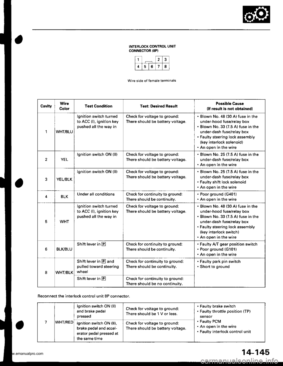
CavityWire
ColorTest CondhionTost: Desired RosultPossible Cause(lf result is not obtainedl
1WHT/BLU
lgnition switch turned
to ACC (l), ignition key
pushed all the way in
Check for voltage to ground:
There should be battery voltage.
Blown No. 48 {30 A} fuse in the
under-hood fuse/relay box
Blown No.33 (7.5 A) fuse in the
under-dash fuse/relay box
Faulty steering lock assembly
{key interlock solenoid)
An open in the wire
YEL
lgnition switch ON (ll)Check for voltage to ground:
There should be battery voltage.
Blown No.25 (7.5 A) fuse in the
under-dash fuse/relay box
An open in the wire
YEUBLK
lgnition switch ON (ll)Check for voltage to ground:
There should be baftery voltage.
Blown No. 25 (7.5 A) fuse in the
under-dash fuse/relay box
Faulty shift lock solenoid
An open in the wire
4BLKUnder all conditionsCheck for continuity to ground:
There should be continuity.
. Poor ground (G401)
. An open in the wire
5WHT
lgnition switch turned
to ACC (l), ignition key
pushed all the way in
Check for voltage to ground:
There should be battery voltage.
Blown No.48 (30 A) fuse in the
under-hood fuse/relay box
Blown No. 33 (7.5 A) fuse in the
under-dash fuse/relay box
Faulty steering lock assembly(key interlock switch)
An open in the wire
BLI(BLU
Shift lever in ECheck for continuity to ground:
There should be continuity,
Faulty Ay'T gear position switch
Poor ground (G101)
An open in the wire
8WHT/BLK
Shift lever in @ and
pulled toward steering
wneel
Check for continuity to ground:
There should be continuity.
Faulty park pin switch
Shon to ground
Shift lever in ECheck for continuity to ground:
There should be no continuity.
Wire side of female terminals
Reconnect the interlock control unit 8P connector.
14-145
7WHT/RED
lgnition switch ON (ll)
and brake pedal
presseo
Check for voltage to ground:
There should be 1 V or less.
Faulty brake switch
Faulty throttle position (TP)
sensor
Faulty PCM
An open in the wire
Faulty interlock control unit
lgnition switch ON (lll,
brake pedal and accel-
erator pedal pressed at
the same time
Check for voltage to ground:
There should be baftery voltage,
www.emanualpro.com
Page 710 of 1395

Valve Gaps
Description
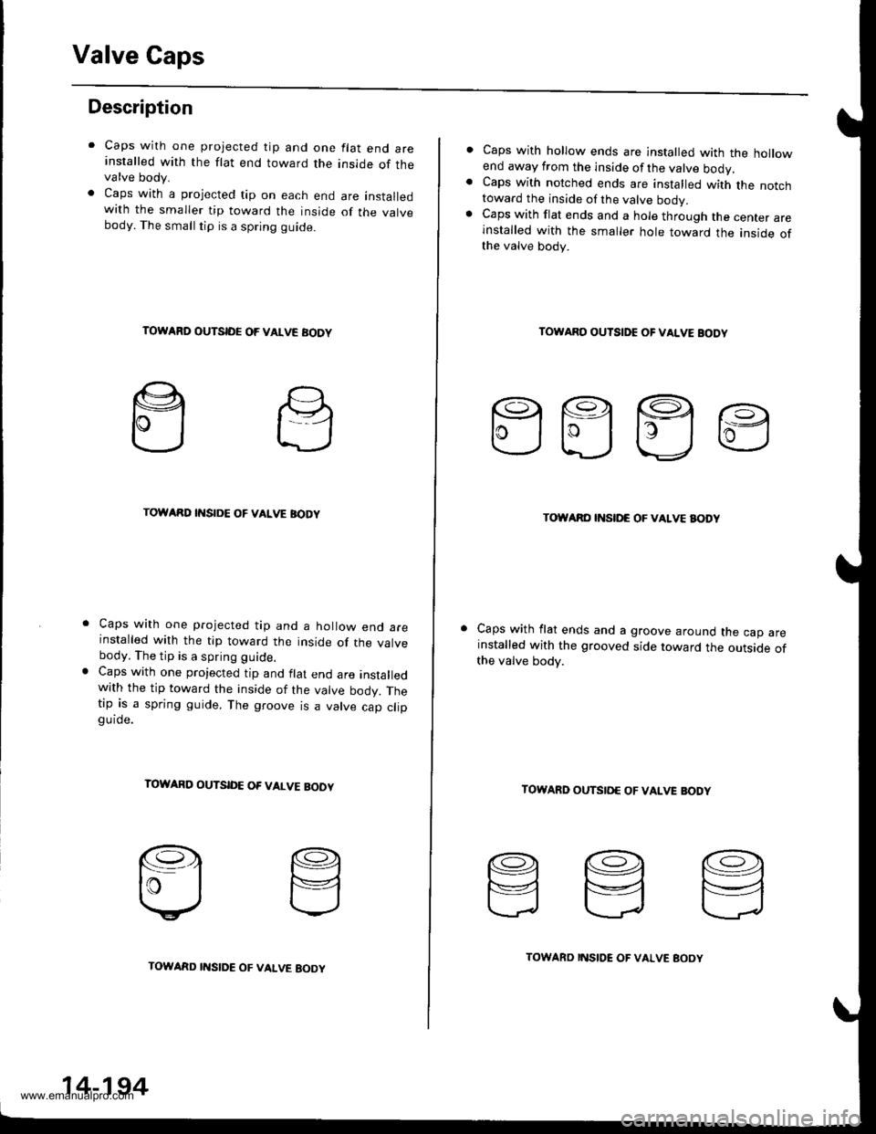
Caps with one projected tip and one flat end areinstalled with the flat end toward the inside of thevalve body.
Caps with a projected tip on each end are installedwith the smaller tip toward the inside of the valvebody. The small tip is a spring guide.
TOWARD OUTSIDE OF VALVE AODY
TOWARD INSIDE OF VALVE BODY
Caps with one projected tip and a hollow end areinstalled with the tip toward the inside of the valvebody. The tip is a spring guide.
Caps with one projected tip and flat end are installedwith the tip toward the inside of the valve bodv. Thetip is a spring guide. The groove is a valve cao cliogu ide.
TOWARD OUTSID€ OF VALVE BOOY
14-194
TOWARD I'{SIDE OF VALVE EOOYTOWARD INSIDE OF VALVE BOOY
Caps with hollow ends are installed with the hollowend away from the inside of the valve ooov.Caps with notched ends are installed with the notchtoward the inside of the valve bodv.Caps with flat ends and a hole through the center areinstalled with the smaller hole toward the inside ofthe valve body.
TOWARO OUTSIDE OF VALVE BODY
EEEE
TOWARO INSII'C OF VALVE BODY
Caps with flat ends and a groove around the cap areinstalled with the grooved side toward the outside ofthe valve body.
TOWARD OUTSIO€ OF VAIVE BODY
www.emanualpro.com
Page 728 of 1395

Sub-shaft Bearings
Replacement
NOTE: Lubricate all parts with ATF before reassembly.
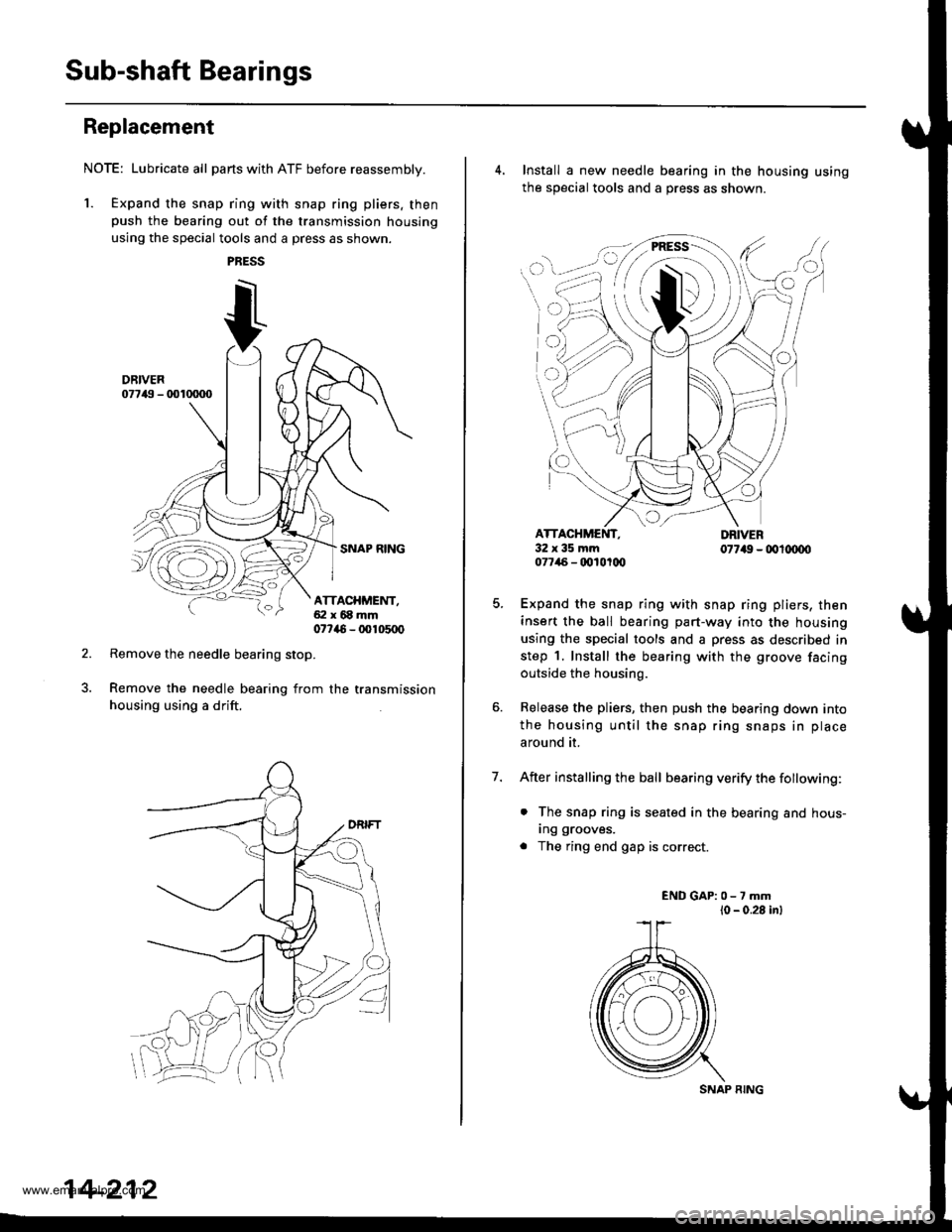
1. Expand the snap ring with snap ring pliers. thenpush the bearing out of the transmission housing
using the special tools and a press as shown.
Remove the needle bearing stop.
Remove the needle bearing from the transmission
housing using a drift.
ATTACHMENT,ai:l x 68 mm07746 - 00105q)
14-212
SNAP RING
4. Install a new needle bearing in the housing using
the sOecial tools and a oress as shown.
7.
cI
32x35mm077/46 - qt10t(x,
Expand the snap ring with snap ring pliers, then
insert the ball bearing part-way into the housing
using the special tools and a press as described in
step 1. Install the bearing with the groove facing
outside the housing.
Release the pliers, then push the bearing down into
the housing until the snap ring snaps in place
around it.
After installing the ball bearing verify the fottowing:
. The snap ring is seated in the bearing and hous-
Ing grooves.
. The ring end gap is correct.
ENDGAP:0-7mml0 - 0.28 inl
www.emanualpro.com
Page 736 of 1395
Clutch
Installthe snap ring.
Reassembly (cont'd)
7.
S AP RIIG
8. Remove the special tools.
9, Install the disc spring in the direction shown.
1ST, 2ND, 4TH, lST-HOLD CLUTCH:
3RD CLUTCH:
Dlsc sPRrrtc
CIUTCH ORUM
otsc sPfitl{c
14-220
10.Soak the clutch discs thoroughly in ATF for a mini_mum of 30 minutes. Before installing the platesand discs, make sure the inside of the clutch drumis free of din or other foreign matter
Starting with a clutch plate, alternatelv install theclutch plates and discs. Install the clutch end platewith its flat side toward the disc.
CLUTCH EI{D PI.ATEInstall in this directior.
CLUTCHCLUTCH EI{D PLATE
12. Install the snap ring.
SCREWDRIVER
't1.
www.emanualpro.com
Page 760 of 1395

Transfer Assembly
18.
Reassembly (cont'dl
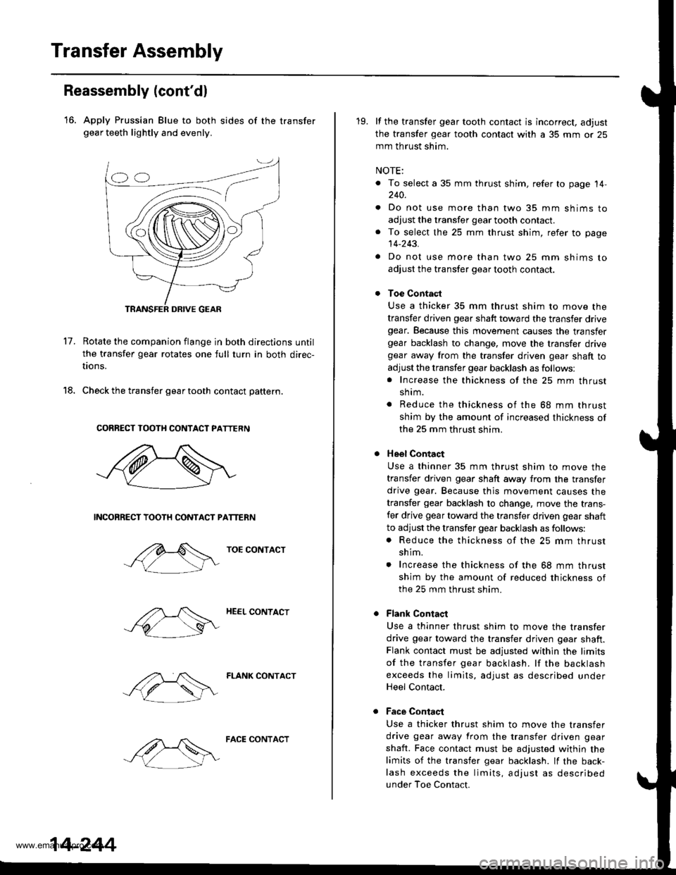
16. Apply Prussian Blue to both sides of the transfergear teeth lightly and evenly.
17.Rotate the companion flange in both directions until
the transfer gear rotates one full turn in both direc-
tions.
Check the transfer gear tooth contact pattern.
CORRECT TOOTH CONTACT PATTERN
NCONRECT TOOTH CONTACT PATTERN
TOE CONTACT
HEEL CONTACT
FLANK CONTACT
14-244
FACE CONTACT
19. lf the transfer gear tooth contact is incorrect, adjust
the transfer gear tooth contact with a 35 mm or 25
mm th rust shim.
NOTE:
. To select a 35 mm thrust shim, refer to page 14,240.
. Do not use more than two 35 mm shims to
adjust the transfer gear tooth contact.. To select the 25 mm thrust shim, refer to page
14-243.
. Do not use more than two 25 mm shims to
adjust the transfer gear tooth contact.
Toe Contact
Use a thicker 35 mm thrust shim to move the
transfer driven gear shaft toward the transfer drivegear. Because this movement causes the transfergear backlash to change, move the transfer drivegear away from the transfer driven gear shaft to
adjust the transfer gear backlash as follows:. Increase the thickness of the 25 mm thrust
shrm.
. Reduce the thickness of the 68 mm thrust
shim by the amount of increased thickness of
the 25 mm thrust shim.
Heel Contact
Use a thinner 35 mm thrust shim to move the
transfer driven gear shaft away from the transfer
drive gear. Because thjs movement causes the
transfer gear backlash to change, move the trans-
fer drive gear toward the transfer driven gear shaft
to adjust the transfer gear backlash as follows:. Reduce the thickness of the 25 mm thrust
shim.
. Increase the thickness of the 68 mm thrust
shim by the amount of reduced thickness ofthe 25 mm thrust shim.
Flank Contaqt
Use a thinner thrust shim to move the transfer
drive gear toward the transfer driven gear shaft.Flank contact must be adjusted within the limits
of the transfer gear backlash. lf the backlash
exceeds the limits, adjust as described underHeel Contact.
Face Contaqt
Use a thicker thrust shim to move the transfer
drive gear away from the transfer driven gear
shaft. Face contact must be adjusted within the
limits of the transfer gear backlash. lf the back-
lash exceeds the limits, adjust as described
under Toe Contact.
www.emanualpro.com
Page 782 of 1395
ATF Cooler Hoses
Gonnection
'1. Connect the ATF cooler hoses to the ATF cooler lines. then secure them with the cliDs.
2. Face the tabs of the clips of the transmission side toward the radiator, and face the tabs of the ATF cooler side down-wa rd.
CLIPFace tabs toward radiator.
ATF COOLER LINEATF COOLER LINE
TRANSMISSION
6-8mm(0.2 - 0.3 inl
ATF COOLER
HOSE CLAMP
CLIPFace tabs downward.
2-rlmm10.1 - 0.2 inl
14-266
www.emanualpro.com
Page 821 of 1395
Front Driveshafts
Disassembly (cont'd)
Double Loop
Mark each roller and inboard joint to identify the
locations of the rollers and grooves in the inboardjoint. Thon remove the inboard ioint on the shop
towel. Be careful not to drop the rollers when sepa-
rating them from the inboard joint.
INBOARD JOINTCheck splines for wear or damage.Check inside bore for wear.Inspect for cracks.
16-6
4, Mark the rollers and spider to identify the locstions
of the rollers on the sDider, then remove the rollers.
BEARING REMOVER(Commercially available) DRIVESHAFT
Remove the circlip,
Mark the spider and driveshaft to identify the posi-
tion ofthe spider on the shaft.
Remove the spider using a bearing remover,
Wrap the splines on the driveshaft with vinyl tape to
prevent damage to the boots and dynsmic damper,
7.
q
INBOARD BOOT
DRIVESHAFT
DYNAMIC DAMPER
Rsmove the inboard boot and dvnamic
Take care not to damage the boot and
damDer.
damper.
dynamic
DRIVESHAFT
Mark
www.emanualpro.com