Page 722 of 2189
PCM Gircuit Diagram (A/T Gontrol System:'99 - 00 Models)
UNOEF DASIFL]SE/FELAY BOX
ta T06 T Dr.
INT€RLOCKCCNTFOLuN|l
ert*rll
I STARTEF
r-->lIl__ sL!
I
UISEF,DASHFISSIEL YmXr,Jo 25 (7 5A) GAUGE ISSEMBLY
Lr GRN -----l l"-- LTGRll
L eultru ----iF erk€Lu
14-44
Page 726 of 2189

Troubleshootin g Procedures
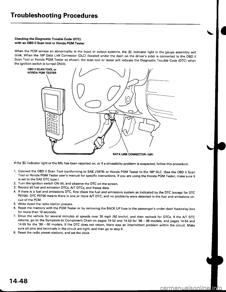
Chccking the Diagnostic Trouble Code IDTC)with an OBD ll Scan tool or Honda PGM Tester
when the PCM senses an abnormality in the input or output systems, the pl indicator light in the gauge assembly willblink. When the 16P Data Link Connector (DLC) (located under the dash on the driver,s side) is connected to the OBD llScan Tool or Honda PGM Tester as shown, the scan tool or tester will indicate the Diagnostic Trouble Code (DTC) whenthe ignition switch is turned ON{ll).
lf the El indicator light or the MIL has been reported on, or lf a driveability problem is suspected, follow this procedure:
1. Connect the OBD ll Scan Tool (conforming to SAE J19781 or Honda PGM Tester to rhe 16p DLC. (See the OBD ll ScanTool or Honda PGM Tester user's manual for specific instructions. lf you are using the Honda PGM Tester, make sure itis set to the SAE DTC type.)
2. Turn the ignition switch ON (lll, and observe the DTC on the screen,3, Record all fuel and emission DTCS, A/T DTCS, and freeze data.4 lf there is a fuel and emissions DTC, first checkthe fuel and emissions system as indicated bythe DTC (except for DTCP0700). DTC P0700 means there is one or more A,/T DTC, and no problems were detected in the fuel and emissions cir-cuit of the PCM.
5. Write down the radio station oresets.
6. Reset the memory with the PGM Tester or by removing the BACK UP fuse in the passenger's under-dash fuse/relay boxfor more than 10 seconds.
7. Drive the vehicle for several minutes at speeds over 30 mph (50 km/hr), and then recheck for DTCS. lf the A"/T DTCreturns, go to the Symptom-to Component Chart on pages 14-52 and 14-53 for'96 - 98 models, and pages 14-54 and14-55 for the'99 - 00 models, lf the DTC does not return, there was an intermittent problem within the circuit. Makesure all pins and terminals in the circuit are tight, and then go to step g.
8. Reset the radio preset stations, and set the clock.
OBD ll SCAN TOOL orHONDA PGM TESTER
DAYA LINK CONNECTOR {16P}
14-44
Page 727 of 2189

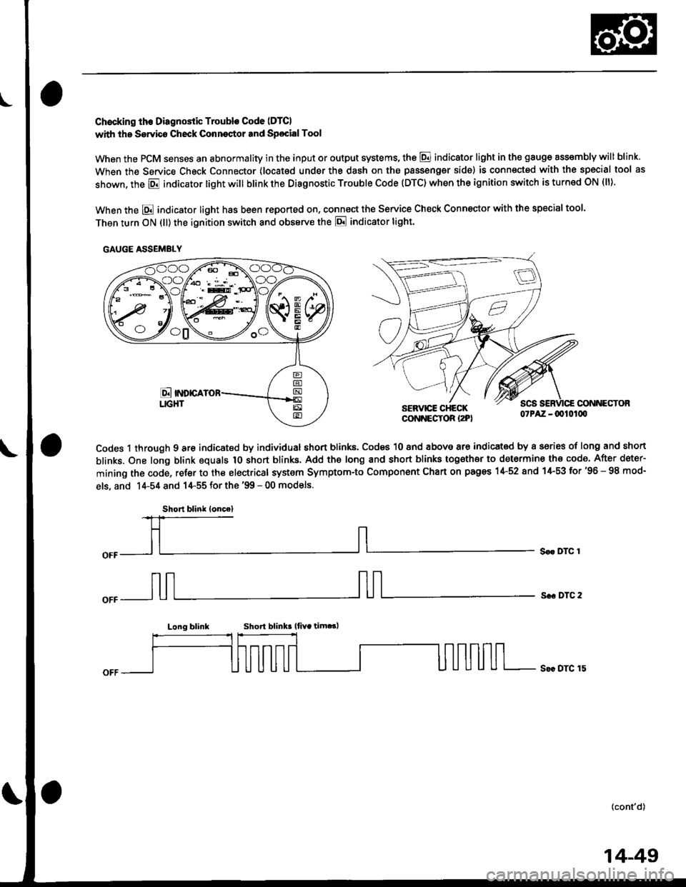
Chocking th€ Diagnostic Trouble Code (DTCI
with the Servico Check Conneqtor and Sp€cialTool
When the PCM senses an abnormality in the input or output systems, the @ indicator light in the gauge assembly will blink
When the Service Check Connector (locat€d under the dash on the passengsr side) is connected with the special tool as
shown, the E indicator light will blink the Diagnostic Trouble Code (DTC) when the ignition switch is turned ON (ll).
When the E indicator light has been reported on, connect the Service Check Connector with the special too'.
Then turn ON (ll) the ignition switch and obssrve the E indicator tight.
CONNECTOBSERVICE CHECKCONNECTOR I2PI07PAZ -0010100
Codes 1 through 9 are indicated by individual short blinks, Codes 10 and above are indicat€d by a sories of long and short
blinks. One long blink equals 1O short blinks. Add the long and short blinks together to determine th€ code. After deter-
mining the code, refer to the electrical system Symptom-to Component Chart on pages 1+52 and 1+53 for'96 - 98 mod-
els, and 14-54 and 14-55 for the '99 - 00 models.
S€r DTC 1
s.. DTC 2
Long blinkShort blink lfiYa tim.!,
S€c DTC 15
(cont'd)
GAUGE ASSEMBLY
Short blink loncel
14-49
Page 755 of 2189
From page 14-76
BRN/BLK
BRN/BLK'96: BLU/RED,97, '98: GRN/BLK
Measure Powor Supply CilcuitVoltage:1. Turn the ignition switch ON (ll).
2. Measure the voltage betweenterminals A9 and A11 andbetween terminals A22 and424.
RGpair opon or short in the wire
boiween the A11 andlot Ml lor'
minals, the PGM-Fl m.in rel.Y,end the tu36 box.
Mo.sure D4 IND Voltago:1. Turn the ignition switch OFF.2. Connect the A {32P} connector
to the PCM.3. Connecl a digital multitester
to the B13 and Ag or A22 ter-minals,4. Turn the ignition switch ON (ll)
and make sure that the voltageis available for two seconds.
Chack tor opan in thc witabctwoon tha 813 larminal andth. gauge ar!.mbly. lf wi.c i!OK, chock for . frulty E indica-tor light bulb or a l.uhy g.ug.
a.!.mbly printod circuit bolrd.
Chock for loose PCM connoctort.Chock tho A/T gGat polition
switch. lI n6ca$sry, substitute aknown-good PCM and rochock.
PCM CONNECTOR A I32PI
Wire side of {emale terminals
14-77
Page 756 of 2189
Electrical Troubleshooting ('96 - 98 Models)
Th6 E indicstor light is on con-st.ntly {not blinkingl wheneveithe ignition switch is ON lll).
Measure 04 IND Voltage:1. Turn the ignition switch OFF.2. Disconnect the B 125P) connec-tor from the PCM.3. Turn the ignition switch ON (ll).
4. Measure the voltage betweenthe 813 terminal and bodyground,
Repair 3hort to pow€. in the wirobetween the 813 terminal endthc gauge asiombly.
Meaiure ATP Dil Voltage:1. Turn the ignition switch OFF.2. Connect the I (25P) connectorto the PCM.3. Turn the ignition switch ON (ll).4. Shiftto any position otherthan
5. Measure the voltage betweenthe 824 terminal and bodygrou nd.
Check for a short to ground on thowir6. It wire i3 OK, .eplac6 the A/Tgoar po3ition indbator,
Troubleshooting Flowchart - E Indicator Light On Constantly
a!
PCM CONNECTOR B (25P)
Wire side of lemale terminals
l.
14-7A
Page 779 of 2189

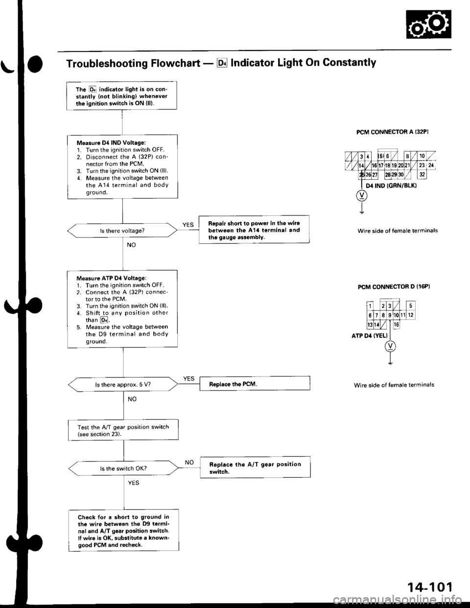
Troubleshooting Flowchart - El Indicator Light On Constantly
PCM CONNECTOR A I32P)
Wire side of lemale terrnanals
PCM CONNECTOR D {16P)
ATP D'
25
61e 11(12
t{Iro
(YELI
Wire side of female terminals
The Dll indicator lighi is on con-stantly {not blinking) whenever
the ignition switch is ON (lll.
Moasure D4 IND Voltage:1. Turn the ignition switch OFF.2. Disconnect the A {32P} con-nector from the PCM.3. Turn the ignition switch ON (ll).
4. Measure the voltage betweenthe A14 terminal and bodyground.
Repsir short to power in the wire
between the A14 torminal andthe gauge assembly.
Measure ATP D4 Voltagel1. Turn the ignition switch OFF.2. Connect the A (32P) connector to the PCM.3. Turn the ignition switch ON (ll).
4. Shitt to any position othertha n [ql.5. Measure the voltage betweenthe D9 terminal and bodyground.
ls there approx. 5 V?
Test the A/T gear position switch(see section 23).
Check Ior a short to ground inthe wire betweon the D9 termi-
nal and A/T gear position switch.It wire is OK, substitute a known-good PCM and recheck.
Page 781 of 2189
From page 14-102
Measu.e D4 IND Voltago:1. Turn the ignition switch OFF.2. Connect the B (2SPiconnector
to the PCM.3. Connect a digital multimeter
to the A14 and 820 or 822 ter-
4. Turn the ignition switch ON (ll),
and make sure that voltage isavailable for two seconds.
Chock for ooon in tho witebetween the A't4 tsrminal .ndthe gauge.3s.mbly. ll wite i3OK, chock to. a t.ulty indicatorlight bulb or. feulty gaugc
e336mbly p.inted circuit board.
Check D4 IND lor a Short Citcuit:Check lor continuity between theA14 terminal and body ground.
Rop.ir short in thc wirg b€twoenth. Al4 tormin.l .nd tho gaugo
a$ombly. ll wiro is OK. chocktho gsugo a3rambly.
ls there continuity?
Check fo. loose terminal tit in thcPCM connectoB. Chock the A/Tgear position switch. It ncce3-sary, substitute a known-goodPCM and rechock.
PCM CONNECTORS
Wire side ol female terminals
14-103
Page 794 of 2189

Stall Speed
Test
CAUTION:
. To prev€nt transmission damage, do not t6st stall speed for more than ro sgconds at a time.. Do not shift the levor while raising the engine speed.. Bo sule lo remove the pressure gauge betoro testing stall speed.
'1. Engage the parking brake, and block the front wheels.
2. Connect a tachometer to the engine, and start the engine.
3. Make sure the Ay'C switch is OFF.
4. After the engine has warmed up to normal operating temperature (the radiator fan comes on). shift into E position.
5. Fully depress the brake pedal and accelerator for 6 to g seconds, and note engine speed.
6. Allow two minutes for cooling, then repeat the test in @ and @ positions.
NOTE:
. Stall speed tests should be used for diagnostic purposes only,. Stall speed should be the same in o., E and E positions.
Stall Spsed RPM:
Specification: 2.700 rpm
Service Limit: 2,550 - 2,850 rDm
TROUBLEPROBABLE CAUSE
. Low fluid level or ATF pump outDur. Clogged ATF strainer. Pressure regulator valve sluck closeo. Slipping clutch
. Slippage of 4th ctutch
. Slippage of 2nd clutch
. Slippage of lst clut"tr or. t"t g""io*-*"y "lut"h
Stall rpm high in D., E and E positions
Stall rpm high in El position
Stall rpm high in E posirion
Stall rpm high in E position
Stall rpm low in LDa . El and E positrons. Engine output low. Torque converter one-way clutch slipping
14-116