Page 1131 of 2189
Wheel/Hub Inspection
\
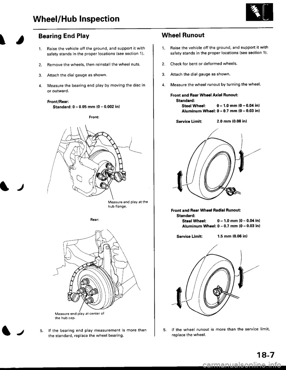
Bearing End Play
1. Raise the vehicle off the ground, and suppon it wjth
safety stands in the proper locations (see section 1).
2. Remove the wheels, then reinstallthe wheel nuts
3. Attach the dial gauge as shown.
4. N4easure the bearing end play by moving the disc in
or outward.
Front/R€ar:
Standard: 0 - 0.05 mm l0 - 0.002 inl
Measure end play athub flange.
t./
Bear:
Measure end PlaY at center ofthe hub cap.
lf the bearing end play measurement is
the standard, replace the wheel bearing.lJmore than
1A-7
Wheel Runout
1. Raise the vehicle off the ground, and support it with
safety stands in the proper locations (see section I I
2. Check for bent or deformed wheels.
3. Attach the dial gauge as shown.
4. Measure the wheel runout by turning the wheel.
Front and Rear Wheel Axisl Runout:
Standard:
Steel Whoel: 0 - 1.0 mm (0 - 0.0,1 inl
Aluminum Wheel: 0 - 0.7 mm (o - 0.03 in)
Servica Limit:2.0 mm (0.08 inl
Front and Rear Wheel Radill Runout:
Standard:
Steol Wheel: 0 - 1.0 mm (0 - 0.04 in)
Aluminum Wheol: 0 - 0.7 mm (0 - 0.03 in)
Service Limit:1.5 mm {0.06 in}
lf the wheel runout is more than the service limit,
replace the wheel.
Page 1156 of 2189
Special Tools
Ref. No. I Tool Numbo]DescriplionOty I Page Reference
o07HAE - SG00100
07JAG - SD40100
07914 - SA50001
Brake Spring Compressor
Pushrod Adjustment Gauge
Snap Ring Pliers
19-28, 33
19-22
o@
19-2
Page 1176 of 2189
Master Cylinder/Brake Booster
Pushrod Glearance Adjustment
NOTEr
. The master cylinder pushrod-to-piston clearancemust be checked and adjustments made, if neces_sary, before installing the master cylinder.. ABS type is shown, conventional brake type is similar.
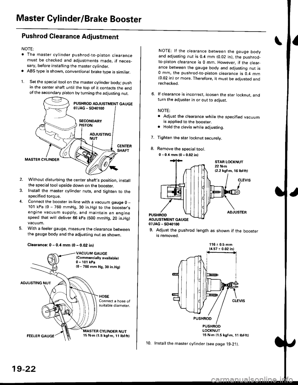
1. Set the special tool on the master cylinde. body; push
in the center shaft until the top of it contacts the endofthe secondary piston by turning the adjusting nut.
Without disturbing the center shaft's Dosition, installthe specialtool upside down on the booster.Install the master cylinder nuts, and tighten to thespecified torque.
Connect the booster in-line with a vacuum gauge O _
101 kPa (0 - 760 mmHg, 30 in.Hg) to the booster,sengine vacuum supply, and maintain an enginespeed that will deliver 66 kpa (500 mmHg, 20 in.Hg)vacuum.
With a feeler gauge. measure the clearance Detweenthe gauge body and the adjusting nut as shown.
Clearance: 0 - 0.4 mm {0 - 0.02 in)
VACUUM GAUGE(Comm€rcially availeblel0 - 101 kPa{0 - 760 mm Hg, 30 in.Hg)
AOJUSTING NUT
FEELER GAUGE
19-22
10.
NOTE: lf the clearance between the gauge bodyand adjusting nut is 0.4 mm (0.02 in), the pushrod-to-piston clearance is 0 mm. However, if the clear_ance between the gauge body and adjusting nut is0 mm, the pushrod-to-piston clearance is 0.4 mm(0.02 in) or more. Therefore, it must be adjusted andrechecked.
6. lf clearance is incorrect, loosen the star locknut, andturn the adjuster in or out to adjust.
NOTE;
. Adjust the clearance while the specified vacuumis applied to the booster.. Hold the clevis while adjusting.
Tighten the star locknut securely.
Remove the special tool.
0 - 0.4 mm (0 - 0.02 in)
7.
ADJUSTERPUSHRODADJUSTMENT GAUGE07JAG - SD('1(x)
9. Adjust the pushrod length as shown if the boosterrs removed.
STAR LOCKNUT22 N.m{2.2 kg,f.m, 16lbtft)
11610.5 mm{{.571 0.02 in)
PUSHRODLOCKNUT15 N.m 11.5 kgf.m, 11 tbtftl
Install the master cylinder {see page l9-21).
Page 1203 of 2189
Gircuit Diagram
MOOULATOR UNIT IOP CONNECTOR
zrJrF!_lll 2 3ll
14TiEltl
c@4
PIMP MOTOR 2P CONNECTOR(Ll number)fFlGTN
UNDER.HOOO A8S FUSE,/FELAY BOX3P CONNECTOR (O number)
| 2 3l
UNDER.HOOD AAS FUSE/RELAY BOX2P CONNECTOR (! number)
| -l
GAUGE ASSEMELY 5P CONNECTOR
---t--t1 t/ 13 )/l5l
Wire side ot temale terminals
- E8l{'Ytr
AA DEF BLY I7.5AI
_@f_u,
n4@f-n,
LEFT.FSONT SOLENOIO
UNDER-OASH FUSSRELAY 8OXZoP CONNECTOR (O numbe,
235678It0tlt3/ i15 /t820
UNDER.OASH FUSE,/RELAY BOX18P CONNECTOR (E numb€r)
23569ll213)t4 /1617
19-50
Page 1207 of 2189
Troubleshooting Precautions
ABS Indicator Light
I The ABS indicator light comes on when the ABS control unit detects a problem in the system. However, even thoughthe system is normal, the ABs indicator light can come on, too, under the following conditions. To determine theactual cause of the problem, question the customer about the problem, taking the following conditions into consider-ation.
. Signal disturbance
. Wheel soin
. Only drive wheels rotate. Battery voltage fluctuates
2. When a problem is detected and the ABS indicator light comes on, the indicator light can stay on untat the ignitionswitch is turned off, or it can automatically go off, depending on the mode.. Lightstayson until the ignition switch isturned off;When the system is inthesvstem down mode.o Light automatically goes off:When the system is in the control inhibition mode.(refer to symptom-to-system chart)3 The ABS indicator light stays on when the system is reactivated without erasing the DTC, but it goes off after startingthe car.
when the wheel sensor system is faulty and the ABS indicator light comes on, the algorithm of the system automaticallyturns off the ABS indicator light after the wheel speed signal returns to the normal speed. while, when the DTC is erased,the CPU is reset and the ABS indicator light goes off when the system check€d out normal by the initial diagnosis.Therefore, test-drive the car after servicing the wheel sensor system, and be sure that the ABS indicator light does notcome on.
4. When the ABS control unit outputs battery voltage to the gauge assembty, the ABS indicator light goes off.
Diagnostic Trouble Code (DTC)
1. The diagnostic trouble code (DTC) is memorized when a problem is detected and the ABS indicator light does not gooff, or when the ABS indicator light comes on.The DTC is not memorized when the ABs indicator right comes on unress the cpU is activated.2. The memory can hold any number of DTCs. However, when the same DTc is detected twice or more, the later one iswritten over the old one.
Therefore. when the same problem is detected repeatedly, it is recorded as one DTC.3. The DTCS are indicated in the order of ascending number, not in the order thev occur.4. The DTCS are memorized in the EEpROM {non-volatile memorv}.Therefore, the memorized DTCS cannot be canceled by disconnecting the battery. perform the specified orocedures toerase.
Solf-diagnosis
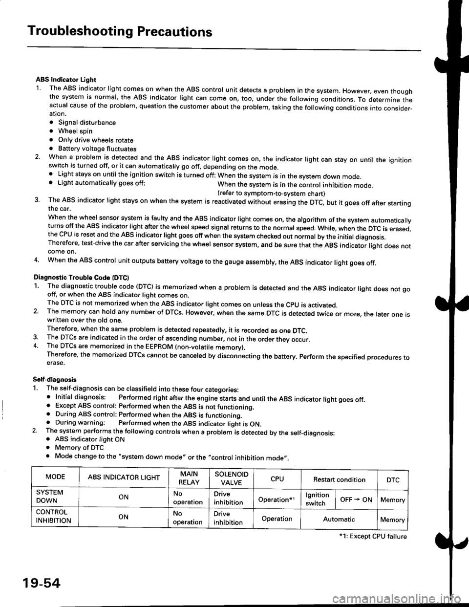
1. The self-diagnosis can be classifield into these four categories:' Initial diagnosis; Performed right after the engine sta rts and untiltheABs indicator light goes off.o Except ABS control: Performed when the ABS is not functioning,. During ABS control: Performed when the ABS is functioning.. During warning: Performed when the ABS indicator light is ON.2 The system performs the following controls when a problem is detected by the self-diagnosis:. ABS indicator light ON. Memory of DTC
. Mode change to the "system down mode,, or the "control inhibition mode,,.
MODEABS INDICATOR LIGHTMAIN
RELAY
SOLENOID
VALVECPURestart conditionDTC
SYSTEM
DOWNONNo
operal|on
Drive
inhibitionOperation+rlgnition
switchOFF - ONMemory
CONTROL
INHIBITIONONNo
operat|on
Orive
inhibitionOperationAutomaticMemory
*1: Except CPU failure
19-54
Page 1213 of 2189
Troubleshooting
ABS Indicator Light Does Not Come On
YES
NOTE:Reinstallthefuse if it is OK.
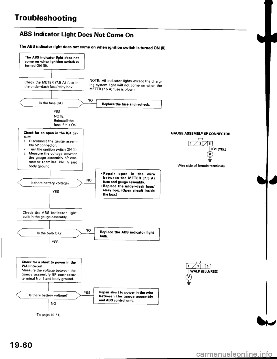
The A8S indicator light does not come on when ignition switch is turned ON ll.
NOTE: All indicator tights except the charg,ing system light will not come on when theMETER 17.5 A) ft se is btown.
NO
GAUGE ASSEMBI"Y 5P CONNECTOR
Wire side of female terminals
Tho ABS indicator light does notcome on wh€n ignition switch istu.ned ON {lll.
check the METEB (7.5 A) fuse inthe under-dash fuse/relay box.
Beplace the tu3e and recheck.
Check for an open in th6 lcl cir-cuii:1, Disconnect the gauge assembly 5P connector.2. Turn the ignitjon switch ON l).3. Measure the voltage betweenthe gauge assembly 5P con-nector terminal No. 5 andbody ground.
. Ropair opan in tho wirobotwe€n thc METER t7.5 Attuso and gauge .$cmbly.. Roplacc th. und.r-dash tus./r.l.y box. lop.r cirouit in3idothe box.l
ls there baftery voltage?
Check the ABS indicator lightbulb in the gauge assembly.
ls the bulb OK?
Ch€ck tor a short to power in theWALP circuit:Measure the voltage between thegauge assembly 5P connectorterminal No. I and body ground.
Replir short to power in tho wiiGb.tweon the gruge rs3embly.nd ABS control unh.
ls there battery voltage?
lTo page 19-61)
19-60
Page 1214 of 2189
{From page 19.60)
Check the geuge a$embly:1. Turn the ignition switch OFF.
2. Connect the gauge assembly
5P connector.3. Connect the terminal No. 3 to
body ground with a iumper
4. Turn the ignition switch ON (ll).
Replace th€ ABS indicato. light
drive circuit in the gauge ai3om-
blY.
Does the ABS indicatorlight come on?
.Repair open in the wire
beiween the gauge assemblYand body ground.. Repair poor ground {G401,G402t.
Jt
GAUGE ASSEMBLY 5P CONNECTOR
,c? "l1t/'.lt/t5 |
JUMPER I GND IBLK}wrRE I-L
t
19-61
Page 1216 of 2189
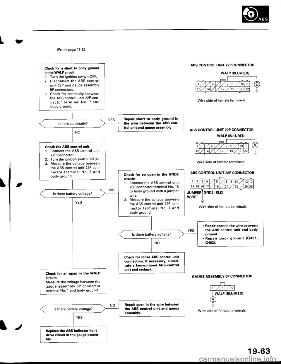
lFrom page 19-621
Ch6ck lor . short to body ground
in ihe WALP Gircuit:1. Turn the ignition switch OFF.
2. Disconnect the ABS control
unit 22P and gauge assembly
5P connectors.3. Check for continuity betweenthe ABS control unit 22P con-nector terminal No. 7 andbody ground.
Ropair short to body g.ound in
tho wire betweon the ABS con_
trol unit and gauge aasembly.
Check the AgS cortrol unit:1. Connect the ABS control unit22P connector.2. Turn lhe ignition switch ON (ll).
3. Measure the voltage between
the ABS control unit 22P con'nector terminal No, 7 and
body ground.Check tor rn open in lho GND2
circuit:1. Connect the ABS control unit26P connector terminal No. 16
to body ground with a iumper
2. Measure the voltage between
the ABS control unit 22P con-
nector terminal No. 7 and
body ground.
ls there baftery voltage?
' Repair op€n in the wit€ betweenthe ABS control unit and bodyground.. Rep.ir poor ground lG40'1,G1(}2t.
ls there battery voltage?
Check tor loo3€ ABS control unitconnector!. lf necesaary, substi_tute a known-qood ABS controlunit and r€check,Check lor an open in the WALP
circuit:Measure the voltage between thegauge assembly 5P connectorterminal No. 1 and body ground.
Ropai. opon in the wiro botweenthe ABS control unit end gauge
assemblv.ls there battery voltage?
Replace the ABS indicrtor lightdriv6 ci.cuit in the gtuge assem-bly.
tv
Wire side ol female terminals
ABS CONTROL UNIT 22P CONNECTOR
ABS CONTROL UNIT 22P CONNECTOR
WALP {BLU/REDI
Wire side ol female terminals
ABS CONTROL UNIT 26P CONNECTOR
rt
GAUGE ASSEMBLY 5P CONNECTOR
.DY
Wire side of female terminals
WALP {BLU/REDI
wire side ol female terminals
J
19-63