Page 1595 of 2189

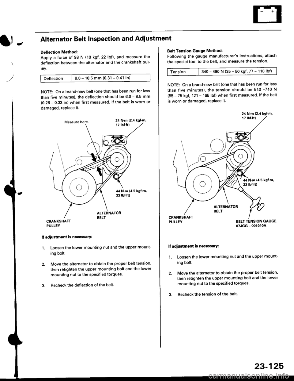
It -Alternator Belt Inspection and Adiustment
Deflection Method:
Apply a force of 98 N (10 kgl,22lbll, and measure the
deflection between the alternator and the crankshaft pul-
ley.
Detlection | 8.0 - 10.5 mm (0.31 - 0.41 in)
NOTE: On a brand-new belt {one that has been run for less
than five minutes). the deflection should be 6.0 - 8.5 mm
(0.26 - 0.33 in) when first measured. If the belt is worn or
damaged, replace it.
CRANKSHAFTPULLEY
lf adiustm€nt is necossary:
1. Loosen the lower mounting nut and the upper mount-
ing bolt.
2, Move the alternator to obtain the proper belt tension,
then retighten the upper mounting bolt and the lower
mounting nut to the specified torques.
3. Recheckthe deflection ofthe belt.
24 N.m (2.4 kgl m,
Belt T€nsion Gauge Method:
Following the gauge manufacturer's instructions. attach
the soecial tool to the belt, and measure the tension.
Tension 340 - 490 N (35 - 50 kgf,77 - 110lbf)
NOTE: On a brand-new belt {one that has been run for less
than five minutes), the tension should be 540 -740 N
(55 - 75 kgf, 121 - 165 lbf) when first measured. lf the belt
is worn or damaged, replace it.
PULLEY BELT TENSION GAUGE
07JGG - 0010104
It adiustment is necossary:
1, Loosen the lower mounting nut and the upper mount-
ing bolt.
2. Move the alternator to obtain the proper belt tension.
then retighten the upper mounting bolt and the lower
mounting nut to the specified torques
3. Recheck the tension of the belt
23-125
Page 1598 of 2189
Gauge Assembly
Component Location Index
SRS components are located in this area. Review the SRS component locations, precautions, and procedures in the SRS
section (24) before performing repairs or service.
6x1.0mm9.8 N.m 11.0 kgf.m,22lbt.lrl
VEHICLE SPEED SENSOR {VSS)Troubleshooting, page 23-1 40
GAUGE ASSEMBLYGau ge/lndicator/TerminalLocation Index, page 23-129Removal, page 23-135Bulb Location, page 23-136Disassembly, page 23 138
PARKING BRAKE SWITCH
FLUIO LEVEL SW]TCH
23-128
ENGINE OIL PR€SSURE SWITCH
Page 1599 of 2189
JGau ge/lndicator/Terminal
With tachometer;
CONNECTOR "A"
{A/T GEAR POSITION INDICATOR}
Location lndex
CONNECTOR "8"
{GAUGE and INOICATOR)CONNECTOB "C"
CONNECTOR "D"
{ABS INDICATORI
SPEEDOMETER:Indicates 60 km/h at 637 rpm or
60 mph at 1,025 rpm o{thevehicle speed sensor (VSS).
A/T GEAR POSITIONINDICATORSee page 23 149
TACHOMETER:Indicates 100 rpm at200 pulses per minuteol the ignition controlmodule (lCMi.FUEL GAUGEENGINE COOLANT TEMPERATURE (ECT) GAUGE
(cont'd)
23-129
(GAUGE end INDICATORI
A1-----------+816
JlltlllulllllrL
c1 --------->c13
1ililil{ilrL
oooo o 0006^
)og @ @ o^o @ )'l |. o
Fl- - -> F5E1_ _ -->E5D1- --+05
oo/ \oo
Gauge/Sending Unit Test, page 23-142
Page 1600 of 2189
Gauge Assembly
Gauge/lndicator/Terminal Location Index (cont'd)
Without tachometer:
CONNECTOR "A"
IA/T GEAR POSITION INDICATORICONNECTOR "8"
{GAUGE and INDICATOR}CONNECTOR "C"
(GAUGE and INDICAIORI
CONNECTOR "F"
{SRS INDICATOR)CONNECTOR "D"
{ABS INDICATORI
SPEEDOMETER:Indicates 60 km/h at 637 rpm or60 mph at 1,025 rpm ofthevehicle speed sensor (VSS).
ENGINE COOLANT TEMPERATUFE (ECT) GAUGEA/T GEAR POSITIONINDICATOFSee page 23 149FUEL
A1 ------> 46
----> al4
B1. - --------------->B16
JilililHililil1
C1-- - --------..+C13
JililHililL
Oo_o-o O 0006
lus 0 0 Bu-. )
oo/ \oo
23-130
Gauge/Sending Unit Test, page 23 142
Page 1601 of 2189
IJNOER,DASHFUSE/RELAY BOX
GAUGELIGHTS
l3wx4 l
CHARGINGSYSTEMLIGHT0.4w)
Gircuit Diagram
UNDEN HOOD FUSE/RELAY BOXIJ
N0.30 (7.54)FUSE
f7
I
tlRED/BLK BEO/BLK
l"l"8LK BLU
IJ
l'"^*
I
t-
G401G402
__l
tE2
IFED/BLU
CRUISECONTROTUNIT
fl ,,1:
tH
I c12
IFFD
VDASH LIGHTSBRIGHTNESSCONTROLLEF
l"'WHT/BLU
vALTERNATOR
(With shifi-up indicatd lighl)(wi1h cruise conlrcl system)
Page 1602 of 2189
Gauge Assembly
(Wnh lachomolgr)
I cNfldt--]I CONTRoL II MODULE
I 0cM) :
tvl
i.ll
|
-i;,
i
TURN SIGNAUHAZAROWARNINGswtTcH
Circuit Diagram {cont'd)
Fh"lurous @)- BLrcwHT + BLKryEL
fi'Sfvrous 16r.- veLPAGE
RIGHT
V
IGR&ryE
LEFT
V
I
No.s (104)FUSE
V
IBEO/GRN
lru
8LU4RE0
ABSCONTROLUNIT
-rl
eLui'rvrr
G401G402G401G442
23-132
Page 1604 of 2189
Gauge Assembly
Circuit Diagram (cont'dl
MATFUNCTIONINOICATOR
(M r)
WASHERLEVELSWITCHTclosed :Floatdownltopen Floal up .l
PNK
BLK
T
G401G402
GRN/ORN
I
ECM/PCM
ENGINEorLPRESSURESWITCHfcbsed Enqine
BLU/BLK YEURED
HI
'f''#lu""',.'f
--
RED/BLU
| ffitt'*'
IV
tl
tl
REDi BLU
I o, u,,,
/h,, SEii
Y rtt'J"T,r.0,.*"0
I
topen Buchred
BLK
T
G552
Page 1605 of 2189
JRemoval
1. Remove the two screws from the instrument panel.
2. Remove the instrument panel.
CAUTION: Carefully remove the instrument panel without damaging the clips.
3. Tilt the steering wheel down with the tilt adjustment lever.
4. Spread a protective cloth over the steering column.
5. Remove the four mounting screws from the gauge assembly.
6. Pry the gauge assembly out, and disconnect all connectors from it
7- Take out the gauge assembly.
GAUGE ASSEMBLY
INSTRUMENT PANEL
23-135