Page 797 of 2189

Pressure Testing
@I While testing, be caroful of th€ rotating front wheels.
. Make sure lifts, iacks, and satoty stands are placod properly (see section 1)'
CAUTION:
. Beforo iesting, be sure the transmission fluid is tilled to tho proper level'
. Warm up tho engine before testing'
1. Raise the vehicle (see section 1).
2. Warm up the engine, then stop the engine and connect a tachometer'
3. Connect the oil pressure gauges to each inspection hole.
TOROUE: 18 N.m (1.8 kgf'm, 13 lbnft)
cAUTloN: connact the oil pressuro gauges securely; be suro not to allow dust and other foreign Parlicles to entel
the inspestion holos'
A/T OIL PRESSURE GAUGESET w/PANEL07t06 - 0020400
A/T LOW PRESSURE GAUGE
SET WPANEL07406 - 0070300
A/T OIL PRESSURE HOSEADAPTER07Mru - PY0120(4 requiJedl
A/T OIL PBESSURE HOSE
2210 mmOTMAJ - PY4{)llA
14 roquircdl
Start the engine, and measure the respective ptessure as follows'
a Line Pressure
. 1st Clutch Pressure
. 2nd,3rd and 4th Clutch Pressure
Install a new washer and the sealing bolt in the inspection hole. and tighten to the specified torque'
TOROUE: l8 N.m (1.8 kgf'm,13lbf'ft)
NOTE: Do not reuse old sealing washers; always replace washers'
(cont'd)
14-119
Page 827 of 2189

Inspection
a Clearance Measurement
NOTE: Lubricate all parts with ATF during assembly.
1, Remove the mainshaft bearing from the transmis-
sion housing (see Page 14-1741.
2. Assemble ths parts below on the mainshaft.
NOTE: Do not assemble the O-rings during inspec-
tlon.
LOCKNUTCONICAL SPRIIIG WASHER
SNAP RING
lST CLUTCH ASSEMBLY
TXRUST WASHER
1ST GEAR COLLAR
TRA SMISSIONHOUSII{G BEARING
THRUST WASHER
4TI{ GEAR COLLAR
2ND/4TH CLUTCHASSEMBLY
THRUST WASHER36.5 x 55 mmSelective part.
THBUST NEEDLEBEARING
2ND GEAR
AEABII{G
IHRUST NEEDLEBEARING
MAINSHAFT
3. Torque the mainshaft locknut to 29 N'm (3.0 kgf'm,
22 tbt,ftl.
NOTE: Mainshaft locknut has left-hand threads.
29 N'm t3.0 kgl'm, 22 lbt'ft)
Hold 2nd gear against the 2nd clutch' then measure
the clearance between 2nd gear and 3rd gear with a
feeler gauge.
NOTE: Take measurements in at least three places,
and use the av€rage as the actual clearance'
STANDARD: 0.05 - 0.13 mm 10.002 - 0.005 in)
THRUST WASHER,36.5 x 55 mm
(cont'd)
1+149
Page 832 of 2189

Gountershaft
Inspection (cont'dl
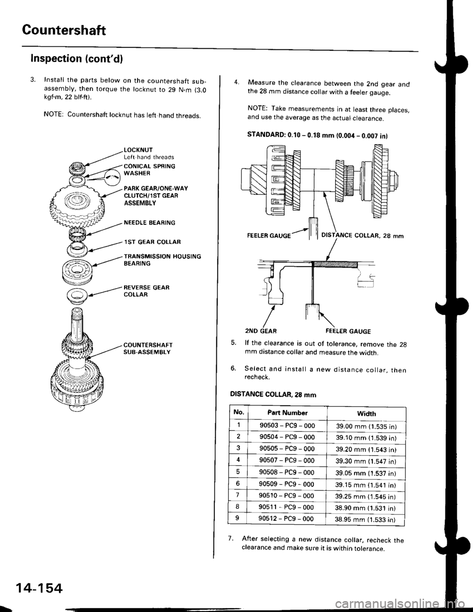
3. Install the parts below on the countershaft sub-assembty, then torque the locknut to 29 N.m (3.0kql.m , 22 blf.ftt .
NOTE: Countershaft locknut has left hand threads.
(=)-----'
v
LOCKNUTLeft hand threads
CONICAL SPRINGWASHER
PARK GEAR/ONE.WAYCLUTCH/1ST GEARASSEMBLY
NEEOLE BEARING
.I ST GEAR COLLAR
TRANSMISSION HOUSINGBEARING
REVERSE GEARCOLLAR
\
14-154
4. Measure the clearance between the 2nd gear andthe 28 mm distance collar with a feeler gauge.
NOTE: Take measurements in at least three places.and use the average as the actuar ctearance.
STANDAFD: 0.10 - 0.18 mm {0.004 - 0.002 inl
lf the clearance is out of tolerance. remove the 2gmm distance collar and measure the width.
Select and install a new distance collar, thenrecheck.
DISTANCE COLLAR, 28 mm
7. Afret selecting a new distance collar, recheck theclearance and make sure it is within tolerance.
OISTANCE COLLAR, 28 mm
No.Part Numb€rwidrh
190503-PCg-00039.00 mm (1.535 in)
290504-PCg-00039.10 mm { 1.539 in)
90505-PCg-00039.20 mm (1.543 in)
90507-PCg-00039.30 mm {1.547 in)
90508-PC9-00039.05 mm (1.537 in)
90509-PCg-00039.15 mm (1.541 in)
790510-PCg-00039.25 mm ( 1.545 in)
I90511-PCg-00038.90 mm (1.531 in)
90512-PCg-00038.95 mm (1.533 in)
Page 872 of 2189

Special Tools
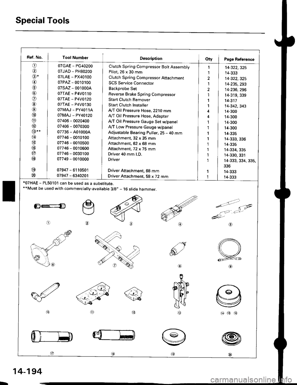
Ref. No. I Tool Number
o
@alr *
@
o
@6l
@
o
@
@-"
@
@
@
o
@
07GAE - PG40200
07JAD - PH80200
07LAE - PX40100
07PM - 0010100
07sM- 0010004
07TAE - P4V01l0
07TAE - P4V0120
07TAE - P4V0130
07 tvlAJ - PY4011A
07MAJ - PY40l20
07406 - 0020400
07406 - 0070300
07736 - A0r 0004
07746 - 0010100
07746 - 0010500
07746 - 0010600
07746 - 0030100
07749 - 0010000
07947 - 6110501
01947 - 6340201
Clutch Spring Compressor Bolt AssemblyPilot. 26 x 30 mm
Clutch Spring Compressor Attachment
SCS Service Connector
Backprobe Set
Reverse Brake Spring Compressor
Stan Clutch Remover
Stan Clutch Installer
A/T Oil Pressure Hose,2210 mmAy'T Oil Pressure Hose, Adapter
Ay'T Oil Pressure cauge Set WpanelAy'T Low Pressure Gauge w/panel
Adjustable Bearing Puller, 25 - 40 mmAttachment, 32 x 35 mm
Attachment, 62 x 68 mm
Attachment, 72 x 75 mm
Driver 40 mm l.D.
Driver
Driver Aftachment, 68 mm
Driver Attachment, 58 x 72 mm
I
1
2
Ia,l
1
1
1,1
1
1'1
I
1
1
't4-322,325
14-333
14-322,325't4-235,293
14-236, 296
r4-319,339't 4-311
14-342,343't4-300
14-300
14-300
14-300
14-335
14-333, 336
14-335
14-334, 335
14-330, 331
14-333, 334, 335,
336
14-333
14-333*07HAE - PL5010l can be used as a substitute.**Must be used with commercially-available 3/8.,- 16 slide hammer.
E*E
o
e
@
>.'.- -t-'- t'\;4
e'o
1:,'Jt*
dAt:-
io(313
@
@
@
@18l
aio
@
IR
L
14-194
Page 940 of 2189

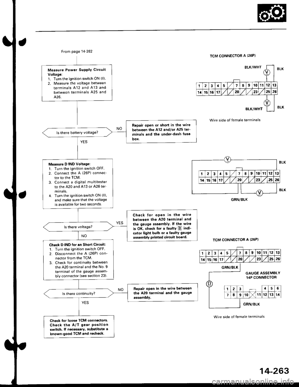
Ftom page 14 262
ls there battery voltage?
Measure Powet SUPPIY Ci.cuit
Voltage:1. Turnthe ignition switch ON (ll)
2. Measure the voltage between
terminals A12 and A13 and
between terminals A25 and
426.
Repair open or short in the wire
between the A'12 andlor Ms ler-
minrls and the under-dash fuse
DOX,
Measure D IND Voltage:1. Turn the ignition switch OFF
2. connect the A (26P) connec
tor to the TcM.
3. Connect a digkal multitester
to the A20 and A'13 or A26 ter
minals.4. Turn the ignition switch ON (ll),
and make sure that the voltage
is available for two seconds.
Check tor opon in the wire
between the A20 l6rminal and
the gaug€ assembly. It the wite
is OK, check tor a faultY ipl indi-
calor light bulb or a faulty gauge
assembly prir ed circuit boatd.
Check D INO for an Shott Circuit:1. Turn the ignition switch OFF
2. Disconnect the A (26P) con-
nector from the TCM.
3. Check for continuity between
the A20 terminal and the No. I
terminal of the gauge assem-bly connector (see section 23).
Bepair open in the wire between
the A20 terminal and the gauge
assembly.
Check tor looso TCM connecto.s.
Check the A/T ge.r Positionswitch. lf nec6ssary, substitute a
known-good TCM and r€check
BLK/WHTI
r
2a710111213
14t5161720232526
BLK/WHT
A
II
TCM CONNECTOR A I26P)
Wire side of female terminals
TCM CONNECTOR A (25P}
BLK
BLK
GRN/BLK
12a58910111213
1l15161720232526
o
GRN/BLK
GAUGE ASSEMBLY14P CONNECTOR
a5
78910111214
GRN/BLK
Wire side of female terminals
Page 941 of 2189
Electrical Troubleshooting ('96 - 98 Modelsl
Troubleshooting Flowchart - lq Indicator Light On Constantly
TCM CONNECTOR A {26PI
Wire side of female terminals
YEL
The E indic.tor light is on con-stantly {not blinking} whoneverthe ignilion switch is ON llll.
Measure D INO Voltage:1. Turn the ignition switch OFF.2. Disconnect the A (26P) con'nector from the TCM.3. Turn the ignition switch ON (ll).4, Measure the voltage betweenthe A20 terminal and bodyground,
Repeir 3hort to power in thc wirebetween tho A20 terminal andihe gauge ass€mbly.
Measure ATP DVohage:1. Turn the ignition switch OFF.2. Connect the A (26P) connec-tor to the TCM.3. Turn the ignition switch ON (ll).4. Shift to any position other thanE,5. Measure the voltage betweenthe A9 terminal and bodygrou nd.
Check tor a short to ground onthe wire. ll wire is OK, .epl.cethe A/T gear position indic.tor.
2347810ll1213
1a15161720232526
GRN/BLK
123a5789101t1213
1at5161720a2526
14-264
-
Page 966 of 2189
From page 14-289
Msaaure D IND Volt.ge:1. Turn the ignition switch OFF.
2. Connect tho B (25Plconnector
to the PCM.
3. Connect a digital multimeter
to the D14 and 820 or 822 ter-
mtnals.il. Turn the ignition switch ON(lll, and make sure that voltage
is available for two seconds
Check for open in the wire
between tha D14 terminal rnd
the gauge a33emblY. lf wiro ia
OK, chock for . frulty indicator
light bulb or a Iaulty gaug.
a3r6mbly printod circuit board.
Check D IND for a Short Circuit:
Check lor continuitY between the
D14 terminal and body ground.
Rgpair 3hort in the wire b.tween
the D14 tcrminal and tho gauge
a*somblY.
Check for loose terminsl fh in the
PCM connectors Check tho A/T
goar posilion switch. It neces'
saiy, iubstitute a known_good
PCM rnd rochock.
PCM CONNECTORS
D {16P1
(BRN/BI.X)D4 IND (GRN/BLK}
Wire side of female terminals
123rs 1/7I215
910nn fT /fl6l112
o lzlzz ,rl/zs 1311- -T---=4'+:l
LG2IBRN/BLKI\=/ |
r lz35
6i /l/t01112
l0
D' IND
o
IGRN/BLKI
4-289
Page 975 of 2189

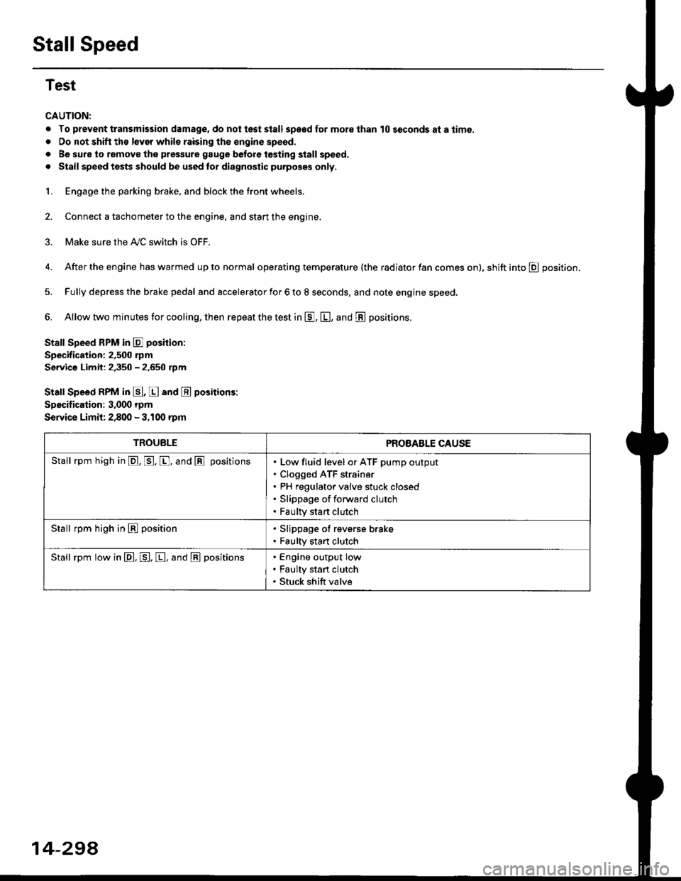
Stall Speed
Test
CAUTION:
. To prevent transmission damage, do not test stall sp€€d for mole than 10 seconds at a time.
. Do not shift the lsver whils raising the engine speod.
. Be sure lo remove the pressure gauge before tosting stall speed.
. Stall speed tssts should be used tor diagnostic purposes only,
1. Engage the parking brake, and block the tront wheels.
2. Connect a tachometer to the engine, and stan the engine.
3. Make sure the A/C switch is OFF.
4. After the engine has warmed up to normal operating temperature (the radiator fan comes on), shift into E position.
5. Fully depress the brake pedal and accelerator for 6 to 8 seconds, and note engine speed,
6. Allow two minutes for cooling, then repeat the test in E, E, and E positions.
Stall Speed BPM in E poshion:
Specification: 2,500 rpm
Servic€ Limit: 2,350 - 2.650 rpm
Stall Speed RPM in E, E and E positions:
Specitication: 3,000 rpm
Service Limit: 2,800 - 3,100 rpm
TROUBLEPROBABLE CAUSE
Stall rpm high in @. p. [, and @ positionsLow fluid level or ATF pump output
Clogged ATF strain€r
PH regulator valve stuck closed
Slippage of forward clutch
Faulty start clutch
Stall rpm high in E position. Slippage of reverse brake. Faulty start clutch
Stall rpm low in E, P, [, and @ positionsEngine output low
Faulty stan clutch
Stuck shift valve
14-294