2000 HONDA CIVIC jump start
[x] Cancel search: jump startPage 374 of 2189

3.
5.
6.
1.
Fuel Cut-off Control
. During deceleration with the throttle valve closed, current to the fuel injectors is cut off to improve fuel economy at
speeds over the following rpm:. D16Y5 engine (M/T):850 rpm. D]6Y5 engine (CVT), D'16Y8 engine (USA M/T): 920 rpm
. Dl6Y8 engine (USA A,/I), D16Y7 engine (USA A,/T);910 rpm
. D16Y8 engine (Canada M/T), D16Y7 engine (canada): 990 rpm
' D16Y8 engine (Canada M/T): 1,000 rpm
. 816A2 engine: 970 rpm
. Fuel cut-off action also takes place when engine speed exceeds 6,900 rpm (D16Y5, D16Y7 engine; D'16Y8 engine:
7,000 rpm. 816A2 engine: 8.100 rpm), regardless of the position of the throttle valve, to protect the engine from
over-rewing. With '99 Dl6Y7 engine (A,/T) and '99 D16Y8 engine (A./T), the PCM cuts the fuel at engine speeds over
5,000 rpm when the vehicle is not moving.
IVC Compressor Clutch Relay
When the ECM/PCM receives a demand for cooling from the air conditioning system, it delays the compressor from
being energized, and enriches the mixture to assure smooth transition to the A,/C mode
Evaporative Emission (EVAP) Purge Control Solenoid Valve*'
When the engine coolant temperature is above 154'F (68'C). the ECM/PCM controls the EVAP purge control solenoid
valve which controls vacuum to the EVAP purge control canister.
Evaporative Emission (EVAP) Purge Control Solenoid Valve*a
When the engine coolant temperature above 154"F (68"C), intake air temperature above 32"F (0'C) and vehicle speed
above 0 mile (0 km/h) or [Ay'C compressor clutch on and intake air temperature above 160"F (41'C)], the ECM/PCM
controls the EVAP purge control solenoid valve which controls vacuum to the EVAP purge control canister.
Exhaust Gas Recirculation (EGR) Control Solenoid Valve*?
When EGR is required for control of oxides of nitrogen (NOx) emissions. the ECM controls the EGR control solenoid
valve which supplies regulated vacuum to the EGR valve
Alternator Control
The system controls the voltage generated at the alternator in accordance with the electrical load and driving mode,
which reduces the engine load to improve the fuel economy.
ECM/PCM Fail-safe/Back-up Functions
1. Fail safe Function
When an abnormality occurs in a signal from a sensor, the ECM/PCM ignores that signal and assumes a pre-pro-
grammed value for that sensor that allows the engine to continue to run.
2. Back-uD Function
When an abnormality occurs in the ECM/PCM itself, the fuel injectors are controlled by a back-up circuit independent
of the system in order to permit minimal driving.
3. Self diagnosis Function lMalfunction Indicator Lamp (MlL)l
When an abnormality occurs in a signal from a sensor, the ECM/PCM supplies ground for the lvllL and stores the DTC
in erasable memory. When the ignition is initially turned on, the ECM/PCM supplies ground for the MIL for two sec-
onds to check the MIL bulb condition.
4. Two Trip Detection Method
To prevent false indications, the Two Trip Detection Method is used for the HO2S, fuel metering-related. idle control
system, ECT sensor, EGR system and EVAP control system self-diagnostic functions. When an abnormality occurs,
the ECM/PCM stores it in its memory. When the same abnormality recurs after the ignition switch is turned OFF and
ON 0l) again, the ECM/PCM informs the driver by lighting the MlL. However, to ease troubleshooting, this function is
cancelled when you jump the service check connector. The MIL will then blink immediately when an abnormality
occurs,
5. Two (or Three) Driving Cycle Detection Method
A "Driving Cycle" consists ot starting the engine. beginning closed loop operation, and stopping the engine. lf misfir-
ing that increases emissions is detected during two consecutive driving cycles, or TWC deterioration is detected dur-
ing three consecutive driving cycles, the ECM/PCM turns the MIL on. However, to ease troubleshooting, this function
is cancelled when you jump the service check connector. The MIL will then blink immediately when an abnormality
occurs.
(cont'd)
1 1-1 05
.1.
Page 376 of 2189

I
Engine Control Module/Powertrain Control Module (ECM/PCM)
t'96 - 98 Models,'99 - 00 Dl6Y5 engine with M/Tl
L
NOTE: lf th is svmptom is intermittent, check for a loose fuse No. 25 {METER 7.5 A) in the
underdash {use/relay box, a poor connection at ECM/PCM terminal A18, or an intermit
tent ooen in the GRN/ORN wire between the ECM/PCM (A18) and the gauge assemblv.
ECM/PCM CONNECTOR A I32PIPGl {BLKI
Wire side ot female terminals
ECM/PCM CONNECTOR A (32P}
Wire side of female terminals
(cont'd)
11-107
The Malfunc{ion Indicator Lamp
{MlLl never comes on (even lor
two secondsl atter ignition is
turned on.
Turn the ignition switch ON (ll).
- Repair short or open in thewile botwoen No. 25 {M€TERI
17,5 Altus€ and gau99 assem'
bty.- Replaco No.25 IMETERI (7,5
A)tuse.
ls the low oil pressure light on?
Try to start the engine.
Does the engine stan?
Check lor an open in the wiles
{PG linosl:1. Turn the ignition switch ON (ll).
2. ldeasure vo ltage betweenbody ground and ECM/PCMconnector terminals A10 andA23 individually.
Check tor an open in the wire ot
bulb (MlL line):1. Turn the ignition switch OFF.
2. Connect the ECM/PCM con-nector terminal A'18 to bodyground with a jumper wire.3. Turn the ignition switch ON (ll).
Repair open in the wire(s)
between ECM/PCM and G101(localod at the thetmostat hous_ingl that had more than 1.0 V.
ls thore less than 1.0 V?
Substituto . known-good ECM/PCM and recheck. It symptom/indication go6s away, roPlace
the origin.l ECM/PCM.
- Repair open in th€ wiresbetwoen ECM/PCM lAl8l andgaug6 a$embly.- Replace the MIL bulb,
ls the MIL on?
Substitute a known-good ECM/
PCM and .echeck. lf symptom/indication goes away, replacothe origin.l ECM/PCM.
268l011
12l3t5t61tIt192022232a
2527xt30
MrL I luanpen wrnrIGRN/ORN) I
!1,
Page 390 of 2189

!Manifold Absolute Pressure (MAPI Sensor -
i;idlga lil;dels,'99 - 00 Dl6Y5 ensine with M/T)
ll
The scan tool indicates Diagnostrc Trouble code (DTC) Po108: A high voltage (low vacuum) problem in the
Manifold Absolute Pressure (MAP) sensor.
MAP SENSOR 3P CONNECTOR ICl11}
MAPIRED/GRNI
JUMPER WIRE
Wire side ol female terminals
vcclIYEL/RED)
ECM/PCM CONNECTOR D (16PI
MAP(RED/GRN)
sG1(GRN/WHT)
Wire side of female terminals
(cont'd)
11-121
The MIL has been reported on
OTC m108 is stolod.
Problem vetitication:
1. Start the engine. Hold the
engine at 3,000 rPm with no
load (in Park or neutral) until
the radiator fan comes on, then
let it idle.
2. Check the MAP with the scan
tool.
lntormittent lailure, sFtom k OK
.t thb time. Chock lor Poor con'
nections or loorg wires at Cll'l
|MAP sensorl snd ECM/PCM.
ls 101 kPa (760 mmHg,30 0 in.Hg)
or higher indicated?
Check tor an open in the MAP
36nSOt:1. Turn the ignition switch OFF
2. Disconnect the MAP sensor
3P connector.3. Install a jumper wire betlveen
the MAP sensor 3P connector
terminals No 3and No 2.
4. Turn the ignition switch ON (ll).
5. Check the MAP with the scan
tool.
ls 101 kPa (760 mmHg, 30 0 in.Hg)
or higher indicated?
Check for an open in wire (SG1
line):1. Remove the iumper wire.
2. Measure voltage between the
MAP sensor 3P connector te.
minals No. 1 and No 2
Rapai. open in the wito batwoen
ECM/PCM (D12) .nd MAP !en.or.ls there approx. 5 V?
Check for an oPon in the wiie
(MAP linel:1. Turn the ignition switch OFF.
2. Connect the ECM/PCM con-
nector terminals D3 and D12
with a iumPer wire.
3. Turn the ignition switch ON (ll).
4. Check the MAP with the scan
tool.
Repair opon in the wiles bstlt oon
ECM/PCM (D3l and MAP 3oGor.ls 101 kPa (760 mmHg, 30 0 in.Hg)
or higher indicated?
Substituto a known'good ECM/
PCM and rochock. ll normal MAP
is indicated, replace tho original
ECM/PCM.
JUMPER WIRE
lr,
Page 391 of 2189

PGM-FI System
Manifold Absolute Pressure (MAPI Sensor
11-122
('99 - 00 Models except D16YS engine with M/T) (contd)
The scan tool indicates Diagnostic Trouble Code (DTC) P0108: A high voltage flow vacuum) problem in theManifold Absolute Pfessure (MAp) sensor,
MAP SENSOR 3P CONNECTOR (C111I
MAPIRED/GRNI
Wire side of female terminals
vcclIYEL/RED)
ECM/PCM CONNECTOR C (31PI
JUMPER WIRE
Wire side of female terminals
Tho MIL has boon rcDortod on.DTC ml 08 b stolod.
Problem verification:'1. Start the engine. Hold theengine at 3,000 rpm with noload (in Park or neutral) untilthe radiator fan comes on, thenlet it idle.2. Check the MAP with the scantoot,
Intormittent f.ilu.e, rystom is OXat thi! time. Chock tor poor con-n6ction3 or looso wirea at C111(MAP 3en.or) and tho ECM/PC-M.
ls 101 kPa (760 mmHg.30in.Hg) or higher indicated?
Check for an open in the MAPaon5('r:1. Turn the ignalion switch OFF.2. Disconnect the MAP sensor3P connector.3. Install a jumper wire betwesnthe MAP sensor 3P conn6ctorterminals No.3 and No.2.4. Turn the ignition switch ON {ll).5. Check the MAP with the scantool.
ls 101 kPa (760 mmHg, 30in.Hg) or higher indicated?
Check fo. an opcn in wiro (SGlline):1. Removo the jumper wire.2. Measure voltage between theMAP sonsor 3P connector terminals No. 1 and No.2.
Roprir opon in tha wiJo bctwoenthc ECM/FCM (C7l rnd the MApsonln t.
ls there approx. 5 V?
Chsck for an open in tho wi.e{MAP lino}:1. Turn the ignition switch OFF.2. Install a jumper wire on theECM/PCM connectors betweenC7 and C17.3. Turn the ignition switch ON (ll).4. Check the MAP with the scantool,
Repair op€n in the wir6a bstwoontho ECM/FCM (C171 and rh6 MApscnltoa.
ls 101 kPa (760 mmHg, 30in.Hg) or higher indicated?
Substituto a known-good ECM/PCM and rechcck, It normal MAPis indiceted. r.place tho originalECM/PCM.
JUMPER WIRE
--
Page 412 of 2189

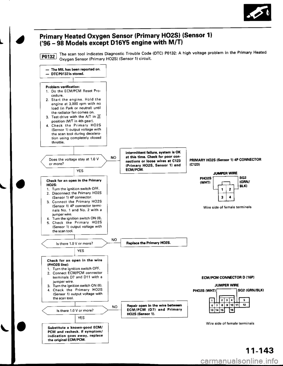
Primary Heated Oxygen Sensor (Primary HO2SI (Sensor 1)
('96 - 9b Models except Dl6Y5 engine with M/Tl
PHO29IWHT}
The scan tool indicates Diagnostic Trouble Code (DTC) P0132: A high voltage problem in the Primary Heated
Oxygen Sensor (Primary H02S) (Sensor'l) circuit.
PRIMARY HO2S (Sonso. 'll 4P CONNECToR
tc123t
sG2IGRN/BLKI
Wire side ot female terminals
ECM/PCM CONNECTOR D I16PI
JUMPER WIRE
PHO2S (WHT}SG2 IGRN/BLKI
Wire side of tem6le terminals
Probl€m verification:1. Do the ECM/PCM Reset Pro-
cedure.2. Start the engine. Hold the
engine at 3,000 rpm with no
load (in Park or neutral) until
the radiator fan comes on
3. Test-drive with the A/T in Eposition (M/T in 4th gear)
4. Check the PrimarY HO2S(Sensor 1) oLltPut voltage with
the scan tool during decelera'tion using completely closed
throttle.
Int.rmittont fiilur., system it OK
at thb timo. Chock for Poot con-
nections or loo3a wir63 at Cl23
lPrimarY HO2S, SensoJ 1l .nd
ECM/PCM.
Does the voltage stay at 1.0 V
or more?
Check for an open in the Primary
HO2S:1. Turn the ignition switch OFF.
2. Disconnect the Primary HO2S(Sensor 1) 4P connector'
3. Connect the PrimarY HO25
lSensor l) 4P connector termi-
nals No. 1 and No. 2 with a
4. Turn the ignition switch ON (ll).
5. Check the PrimarY H02S(Sensor 1i outPut voltage with
the scan tool.
lsthere 1.0 V or more?
Check for an open in the wiro
{PHO2S line):1. Turn the ignition switch OFF.
2. Connect EcM/PcM connector
terminals D7 and D11 with ajumper wrre,3. Turn the ignition switch ON lll)4. Check the PrimarY HO2S(Sensor 1) output voltage withthe scan tool,
Replir open in tho wirc b€twccnECM/PCM lo?) and Prim!.Y
HO2S lsonsor 1).ls there 1.0 V or more?
Substitute a known-good ECM/PCM and recheck. lf 3ymptom/indicetion goos awey, roplacethe oliginal ECM/PCM.
11-143
Page 413 of 2189

PGM-FI System
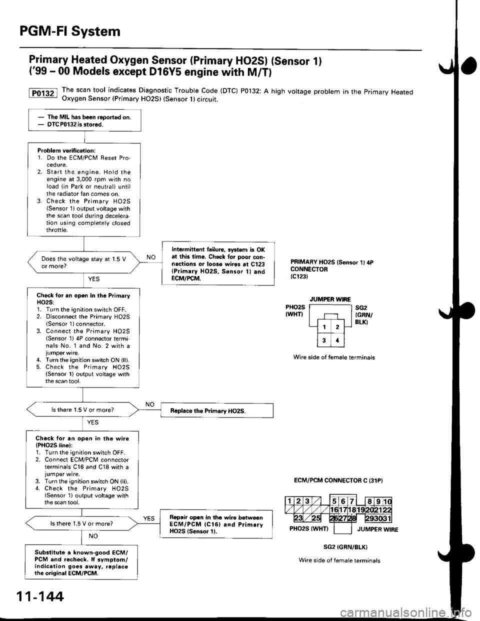
Primary Heated Oxygen Sensor (Primary HO2SI (Sensor 1)
('99 - 00 Models except D16Y5 engine with M/T)
The scan tool indicates Diagnostic Trouble Code (DTC) P0132: A high voltage problem in the primary HeatedOxygen Sensor (Primary HO2S) {Sensor I ) circuit.
PRIMARY HO2S ls€n3or 1' 4PCONNECTOR(c123t
PHO2SIWHTI
Wire side of temale terminals
ECM/PCM CONNECTOR C 131PI
sG2(GRN/
BLK)
SG2 IGRN/8LK}
Ware side of female terminals
The MIL has been reported on.OTCP0132 is stored.
Problem vorificalion:1. Do the ECM/PCM Reset Procedure,Start the engine. Hold theengane at 3,000 rpm with noload (in Park or neutral) untilthe radiator fan comes on.Check the Primary HO25{Sensor lioutput voltage withthe scan tool during decelera-taon using completely closedthrottle.
Intermittent tailure, systom k OKat this time. Chock tor poor con-nections or looso wir* at Cl23(Primaly HO2S, Sonsor 1) andECM/PCM.
Check lor an open in the PrimaryH02S:1. Turn the ignition switch OFF.2. Disconnect the Primary HO2SlSensor 1)connector.3. Connect the Primary H02S(Sensor 1)4P connector terminals No. 1 and No. 2 with a
4. Turn the ignition switch ON (ll).5. Check the Primary H02S{Sensor l) output voltage withthe scan tool.
ls there 1.5 V or more?
Check lor an open in th€ wire(PHO25 lin€l:1. Turn the ignition switch OFF.2. Connect ECM/PCM connectorterminals C16 and C18 with ajumper wire.3. Turn the ignition switch ON {lli.4. Check the Primary HO2S(Sensor 1i output voltage withthe scan tool,
Roptir op.n in tho wire betweonECM/PCM lCl6l and Prim.ryHO2S lsensor 11.
ls there 1.5 V or more?
Subsiitute a known-good ECM/PCM and r.check. lf symptom/indication goos away, replecethe original ECM/PCM.
11-144
Page 423 of 2189

PGM-FI System
I
a
a
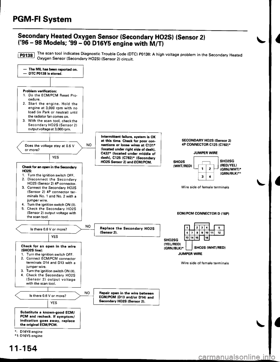
9ggoqOfry Heated Oxygen Sensor (Secondary HO2S) {sensor 2l('96 - 98 Models; '99 - 00 D16YS engine with M/Tl
The scan tool indicates Diagnostic Trouble Code (DTC) PO'138: A high voltag€ problem in the Secondary HeatedOxygen Sensor (Secondary HO2SI (sensor 2) circuit.
SECONDARY HO2S ls.nsor 2l4P CONNECTOR C125 tc782t*
JUMPER WIRE
sHo2sIWHT/RED}
sHo2sG(RED/YEL)(GRN/WHT)*(GRN/BLK)*'
Wire side of female terminals
ECM/FCM CONN€CTOR D Il6PI
sH()2sG{YEL/RED){GRN/BLK}'
JUMPER WINE
Wire side of female terminals
'i D16Yg engine*1i Dl6Y5 engine
- Ths MIL ha3 bcen r6port.d on.- DTC m138 i. 3tored.
Problem vorilication:1. Do the ECM/PCM Reset Pro-cedure.2. Start the engine. Hold theengine at 3.000 rpm with noload (in Park or neutral) untilthe radiatorfan comes on.3. With the scan tool, ch€cktheSecondary HO2S {Sensor 2)outputvoltageat 3,000rpm.
Into.mittant failurc, sy3tem b OKrt thi3 tims. Ch6ck tor poor con-n6clionr or loo3€ wiroa at C13'l*(locat d und6r right lido of dr'h),C/€2r (loc.tod und€r middle old.rhl, C125 {C782lr (Socond.ryHO2S S6n3or 2) .nd ECM/PCM.
Chcd( for rn open in the Socond!ryf|o2s:1. Turn the ignition switch OFF.2. Disconnect the SecondaryHO2S (Sensor 2) 4P connector.3. Connect the Secondary HO2S(Sensor 2) 4P connector ter-minals No. 1 and No.2 with aJUmper wire.4. Tu.n the ignition switch ON (ll).5. Chock the Secondary HO2S(Sensor 2) output vollage withthe scan tool.
ls there 0.6 V or more?
Check tor an open in the wiro(SHO2S lin6l:1. Turn th6 ignition switch OFF.2. Connect ECM/PCM connectorterminals D14 and D13 with ajumper wire.3. Turn the ignition switch ON {ll}.4. Check the Secondary HO2S(Sensor 2) oltput voltagewith the scan tool.
Rapair op.n in the wiio botw.onECM/PCM lD13 and/or Dlal andS.cond.ry HO2S ls€nsor 21.
ls thore 0.6 V or more?
Subslituto a known-good ECM/PCM .nd rccheck. lt symptom/indication goe! rway, replacethe original ECM/PCM.
11-154
Page 424 of 2189

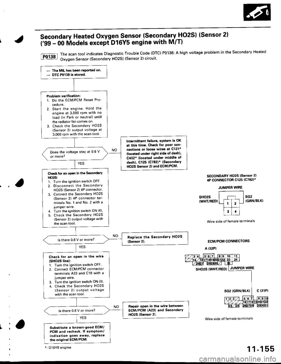
Secondary Heated Oxygen Sensor (SecondarytlO2S) (Sensor 2l
('99 - 00 lilodels except DtGYS engine with M/T)
The scan tool indicates Diagnostic Trouble code (DTC) P0138: A high voltage problem in the secondary Heated
Oxygen Sensor (Secondary H02S) (Sensor 2) circuit.
SECONDARY HO2S {S€nsot 2}
4P CONNECTOR Cl25 lc782l'
JUMPER WIRE
Ir
sH02s(WHT/RED)sG2{GRN/BLKI
Wire side of female termanals
ECM/PCM CONNECTORS
A (32P1
Wire side ot female termlnals
gs92g 111yp17p5py | .lutuPea wtne
- The MIL has beon reportod on.- DTC m138 is.tored.
Ploblem vorification:1. Do the ECM/PCN4 Reset Pro-
cedure.2. Start the engine Hold the
engine at 3,000 rpm with no
load (in Park or neutral) until
the radiator{an comes on
3. Check the SecondarY H02S(Sensor 2) output voltage at
3,000 rpm with the scan tool
lntormittont failuio, sYstom b OK
st thir timo. Check for Poor con_
nections ot loo39 wiJo3 af Cl3lr(located under right ride ot desh),
C432' (locatod undot middle of
dashl, Cl25 {C782lr (Secondaiy
HO2S Son3or 2l and ECM/PCM.
Does the voltage stay at 0 6 V
or more?
Ct€d( tor an opan in the Secondary
l|o2s:1. Turn the ignition switch OFF
2. Disconnect the SecondarY
HO2S (Sensor 2) 4P connector.
3. Connect the Secondary HO2S(Sensor 2) 4P conneclor ter_
minals No. 1 and No.2 with a
iumper wire.4. Turn the ignition switch ON (ll)
5. Check the SecondarY HO2S
lSensor 2) outptlt voltage with
the scan tool,
lsthere 0.6 V or more?
Check lor an open in the wiro(SHO2S line):1. Turn the ignition switch OFF.
2. Connect ECM/PCM connector
terminals A23 and C18 with ajumper wrre,
3. Turn the ignition switch ON (ll).
4. Check the SecondarY HO2S
{Sensor 2) outPut vo ltage
with the scan tool.
Repair opon in tho wire betwecn
ECM/PCM (A23) and SocondarY
HO2S {Sansor 2).ls there 0.6 V or more?
Substitut€ a known'good ECM/
PCM and recheck. It symptom/indication goes awey, JePlaco
the otiginel ECM/PCM
*i 016Y8 engine1 1-155