Page 280 of 2189
\-
816A2 engine:
AIR CLEANER (ACLI
Replacement, Page 11-244
THROTTLE BODY {T8)Inspection. page 11-247Removal, page 1 '1-248
Disassembly, page 1 1-249THROTTLE CABLElnspection/Adiustment, page 1 1 -244
lnstallation, page 1 1-245
POSITIVE CRANKCASEVENTILATION IPCVI VALVEInspection, page 1 1-266
11-11
Page 377 of 2189

PGM-FI System
Engine Control Module/Powertrain Control Module (ECM/PCMI
('96 - 98 Models,'99 - 00 Dl6Y5 engine with M/Tl (cont'd)
NOTE:. When there is oo Diagnostic Trouble Code (DTC) stored, the MtL wi
stay on if the SCSservace connector is connected and the ignition switch is on,. lf this symptom is intermittent, checklor:- A loose Fl E/M 115 A) fuse in the under hood luse/relay box- A loose No. 13 FUEL PUMP fuse (15 A) in the underdash fuse/relay box- An intermittent shon in the wire between the ECM/PCM (C7) and the service cnecKconnector- An intermittent short in the wire between the ECM/PCM (A18) and the gaugeassembly- An intermittent shon in the wire between the ECM/PCM {D4) and the MAp sensorAn intermittent short in the wire between the ECM/PCM (D10), the Tp sensor, theEGR valve l:ft sensor (D16Y5 engine) and/or the Fuel tank pressure sensor (,96Dl6Y8 engine (coupe), '97 016Y7 engine (coupe: KL model, sedan: KL (LX) modeli,'97 016Y8 engine {coupe: all models, sedan: KL modeti,'98,all models}- PGM-FImain relay. See the OBD ll scan tool or Honda PGM Tester user's manuals lor specitic operatinginstructions.
ECM/PCM CONNECTOR C 13lPI
Wire side of female terminals
(To page 11 109)
(To page 11,109)
11-108
The Maltunction Indicator Lamp(MlLl stays on o. comes on eftartwo s€conds,
Check the Oiagnoslic TroubleCode {DTC}I1. Connect a scan tool or HondaPGM Tester.2. Turn the ignition switch ON (ll).
3. Read the DTC with the scantool or Honda PGM Tester.
Go to troubleshooting p.oc€dur€s(se€ pago 11{11.Are any DTC{s) indicated?
Check the DTC by MIL indication:1. Turn the ignition switch OFF.2. Connect the SCS service con,nector to the service checkconnector.3. Turn the ignition switch ON (lli.
Repair opon ol short in wirebotwoen the ECM/PCM (C8)
and Data Link Connector.Go to troublelhooting proce-dure ls6e page 11-811.
Does the MIL indicate any DTC?
Try to start the engine.
Does the engine start?
Check for a short in the wire(SCS lin€l:1. Disconnect the SCS serviceconnector.2. Stop the engine and turn theignition switch ON {lli.3. Measure voltage between theECM/PCM connector terminalC7 and body ground.
Ropair short to body Iround inthe wire betweon ECM/PCM lCTland sorvice check connector.
ls there approx. 5 V?
scs tBRNI
Page 485 of 2189

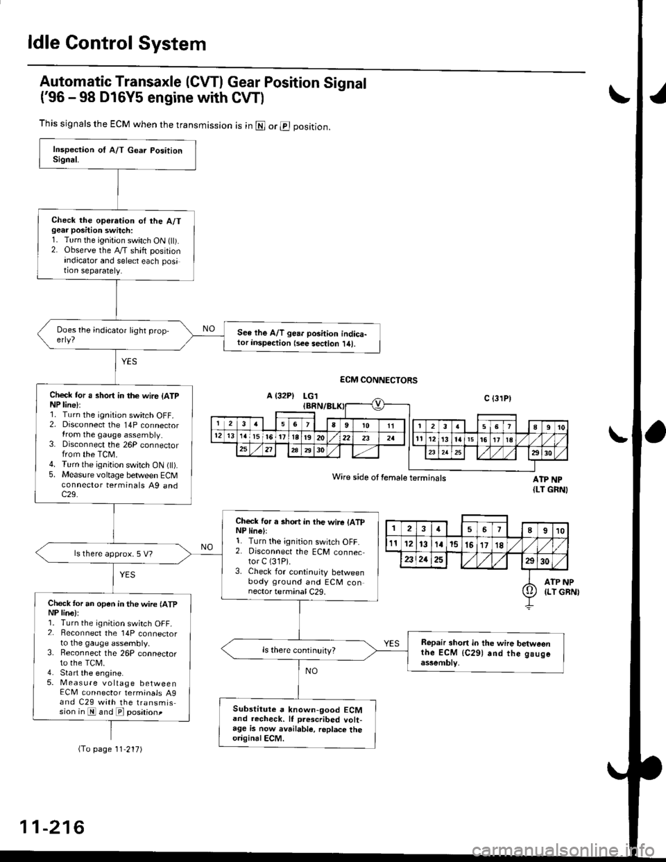
ldle Control System
Automatic Transaxle (CVTI Gear Position Signal
('96 -98 D16Y5 engine with CW)
ATP NP{LT GRNI
INP
GBN)
This signals the ECM when the transmission is in @ or @ position.
Check the operation oI the A/Tgear position switch:1. Turn the ignition switch ON flt).2. Observe the A/T shift positionindicator and select each position separately.
See lhe A/T gear position indica-tor insp€ction {see sec{ion l/tl.
Check tor a short in the wir6 (ATpNP line):1. Turn the ignition switch OFF.2. Disconnect the 14P connectorIrom the gauge assembly.3. Disconnect the 26P connectorfrom the TCM.4. Turn the ignition switch ON fll).5. Measure voltage between ECMconnector terminals A9 andc29.
Check for a short in the wire lATpNP linell1. Turn the ignition switch OFF.2. Disconnect the ECM connector C (31P).
3. Check for continuity betweenbody ground and ECM connector terminal C29.
ls there approx. 5 V?
Check for an open in the wire lATpNP lina):1. Turn the ignition switch OFF_2. Beconnect the 14P connectorto the gauge assembly.3. Reconnect the 26P connectorto the TCM.4. Sta rt the engine.5. Measure voltage betweenECM connector terminals A9and C29 with the transmission in E and E posationt
Repair short in the wire betweenthe ECM {C291 and the gaugeassemblv,
Substitute a known-good ECMand recheck. lf prescribed volt-age is now avrilable, replace theo.iginalECM.
Wire side ot female terminals
2457I910
t112131a15151718
2321252930
ATP(LT io
(To page 11'217)
11-216
Page 498 of 2189
t
Belore connecting a new fuel tube/quick-connect fining
assembly, remove the old retainer from the mating pipe
with thetabs pulled
apan, removeand discard the
I
retarner
New FUEL TUBE/OUICK.CONNECTFITTING ASSEMELY
3. Align the quick-connect fiftings with the pipe, and
align the retainer locking pawls with the connector
grooves. Then press the quick-connect fittings onto
the pipe until both retainer pawls lock with a click-
ing sound.
NOTE: lf it is hard to connect, put a small amount
of new engine oil on the pipe end.
Connection with new retainer:
4. Make sure the connection is secure and the pawls
are firmly locked into place; check visually and by
pulling the connector.
RCTAINER
Reconnect the battery negative cable, and turn the
ignition switch ON (ll). The fuel pump will run for
about two seconds, and fuel pressure will rise.
Repeat two or three times, and check that there is
no leakage in the fuel supplv system
11-229
Page 517 of 2189
Intake Air System
J
Throttle Body (cont'dl
Removal
D16Y5, Dl6Y8, 81642 engine:
D15Y7 engine:
AIR CLEANER
{ACLI
22 N.m12.2 kgl.m,16 rbf.ftl
NOTE:
. Do not adjust the throttle stop screw.. After reassembly, adjust the throttle cable {see page l l-244).. The TP sensor is not removable.
IAT SENSOR
MAP SENSOR
GASKETReplace.
11-248
THROTTLE CABLE
Page 586 of 2189

Transmission Assembly
Removal (cont'dl
8. Remove the driveshafts (see section 161.
NOTE: Coat all the precision finished surfaces with
clean engine oil or grease. Tie plastic bags over the
driveshaft ends,
DRIVESHAFT
10 x 1.25 mrn43 N.m 14.4 kgt.m,32 rbf.frl
COTTER PINReplace. SELF12 x 1.25 mm49-59 N.m (5.0 -6.0 kgt.m,36-43 lbf.ft)
9. Remove exhaust pipe A.
Replace.12 x 1.25 mm64 N.m {6.5 kgt.m,47 lbf.tr)
GASKETSReplace.
IF\sELF-LocKtNG NUT.''1/Replace.8 x 1.25 mm16 N.m {1.6 kgf'm,12 tbf.ft)
EXHAUSTPIPE A
SELF-LOCKING NUTReplace.I x 1.25 mm22 N.m (2.2 kgf.m,16 tbt'fr)
SELF-LOCKING NUTReplace.D16Y5, D16Y7 engines:
33 N.m {3.4 kgf.m,25 lbt.ft)D16YB engine:10 x 1.25 mm54 N.m 15.5 kgl'm,40 lbf.ttl
SET RING
13-6
v'10. Remove the shift rod and extension rod.
SI'IIFT BOD
8x22mmSPRING PINReplace.
EXTENSION ROD
PIN PUNCH, 8.O mm(Commercially available)f-
'1'1. Remove the engine stiffeners and clutch cover.
D16Y5, D16Y8 engines:
10 x 1.25 mm44 N.m (4.5 kgt.m,33 tbf.tr)
I x 1.25 mm24 N.m (2.4 kgf.m17 lbt.frl
COVER
8 x 1.25 mm24 N.m 12.4 kgf'tn,17 tbt.tr)
Page 588 of 2189

Transmission Assembly
Removal(cont'd)
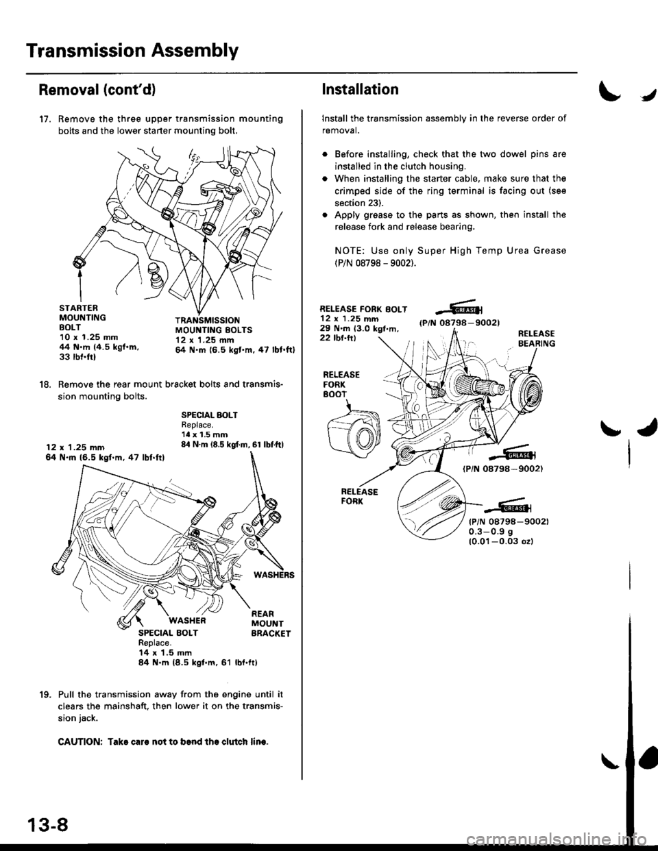
17. Remove the three upper transmission mounting
bolts and the lower starter mounting bolt,
STARTERMOUNTINGBOLT10 x 1.25 mm44 N.m (4.5 kgf.m,33 rbnftl
TRANSMISSIONMOUI{TING EOLTS12 x 1.25 mm& N.m (6.5 kgt'm,47 lbl.ftl
18. Remove the rear mount bracket bolts and transmis-
sion mounting bolts.
12 x 1.25 mm64 N.ft 16.5 kgl.m,47 lbl.ftl
SPECIAL BOLTReplace.'ll x 1.5 mm84 N.m (8.5 kgf.m, 61 lbf.ftl
SPECIAL BOLTReplace.14 x 1,5 mln84 N.m (8.5 kgl.m, 61
WASI{ERREARMOUNTBRACKET
rbl.ftt
Pull the transmission away from the engine until it
clears the mainshaft. then lower it on the transmis-
sion jack.
CAUTION: Take caro not to b6nd tho clutch lin€.
1(|
Installation
Install the transmission assembly in the reverse order of
removal.
Before installing, check that the two dowel pins are
installed in the clutch housing.
When installing the starter cable, make sure that the
crimped side of the ring terminal is facing out (see
section 23).
Apply grease to the parts as shown, then install the
release fork and release bearing,
NOTE: Use only Super High Temp Urea Grease
(P/N 08798 - 9002).
RELEASE FORK BOLT12 x 1.25 mm29 N'm 13.0 kgt,m,(P/N 08798-90021
22 tbl.ttlR€LEASEBEARING
J
RELEASEFORK8()07
ra
{PiN 08798-9002)
tP/N 08798-900210.3-0.9 g
10.01-0.03 ozl
Page 591 of 2189

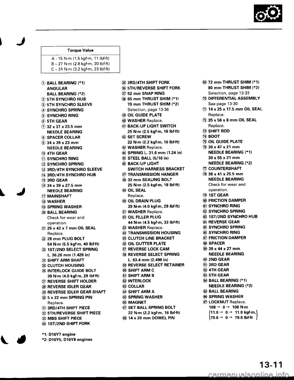
Torque Value
A - 15 N.m (1.5 kgf.m, 1'1 lbf.ft)
B - 27 N.m (2.8 kgf.m. 20 lbift)
C - 31 N.m {3.2 kgnm, 23 lbift)
\
O BALL BEARING (*T)
ANGULAR
BALL BEARING {*2I
O 5TH SYNCHRO HUB
O 5TH SYNCHRO SLEEVE
€) SYNCHRO SPRING
o SYNCHRO B|NG
@ 5TH GEAR
@ gz xgt x 23.5 mm
NEEDLE BEARING
@ SPACER COLLAR
@34x39x23mm
NEEDLE BEARING
(D 4TH GEAR
O SYNCHRO RING
C) SYNCHRO SPRING
CO 3RD/4TH SYNCHRO SLEEVE
@ 3RD/4TH SYNCHRO HUB
(} 3RD GEAR
@34x39x27.5mmNEEDLE BEARING
G) MAINSHAFT
G) WASHER
@ SPRING WASHER
@ BALL BEARING
Check for wear and
operation.(E 26x42x7 mm OIL SEAL
Replace.
@ 28 mm PLUG BOLT
5,1 N.m {5.5 kgf'm, /t0 lbt'ft)
@ lsT/zND SELECT SPRING
L. 36.26 mm (1./P8 in)
@ SHIFT ARM SHAFT
@ CLUTCH HOUSING
@ INTEELOCK GUIDE BOLT
39 N.m (4.0 kgf.m, 29 lbf.ftl
@ REVERSE SHIFT HOLDER
@ REVERSE IDLER GEAR
@ REVERSE IDLER GEAR SHAFT
@ 5 x 22 mm SPRING PIN
Replace.
@ 3RD/4TH SHIFT PIECE
@ 5TH/REVERSE SHIFT PIECE
@ MBS SHIFT PIECE
@ 1ST/2ND SHIFI FORK
*1:D16Y7 engine*2: D16Y5, D16Y8 engines
@ 3RD//|TH SHIFT FORK
@ 5TH/REVERSE SHIFT FORK
@ 52 mm SNAP RING
@ 65 mm THRUST SHIM (*11
70 mm THRUST SHIM (*21
Selection, page 13-36
@ OIL GUIDE PLATE
@ wASHER Replace.
@ BACK.UP LIGHT SWITCH
25 N.m (2.5 kgf'm, 18 lbf'ft)
@ sET SCREW
22 N.m {2.2 kgf.m, 16 lbl.ft}
@ WASHER Replace.
@D SPRING 1.31.6 mm (1.2,1inl
@ STEEL BALL 15/16 in)
@ BACK-UP LIGHT
SWITCH HARNESS BRACKET
@ TRANSMISSION HANGER
@ 32 MM SEALING BOLT
25 N.m (2.5 kgf.m, 18 lbt'ft)
@ OIL SEAL
Replace.
@ OIL DRAIN PLUG
39 N.m (4.0 kgf.m, 29 lbf.ft)
@ WASHER Replace.
@} OIL FILLER PLUG
44 N.m (4.5 kgf.m, 33 lbf'ftl
@ WASHER Replace.
@) TRANSMISSION HOUSING
€) CLUTCH LINE BRACKET
@ OIL GUTTER PLATE
@ REVERSE LOCK CAM
@ REVEBSE SELECT SPRING
L. 63.4 mm {2.,196 in)
@ REVERSE SELECT RETAINER
@ SHIFT ARM C
@ SHIFT ARM B
@ INTERLoCK
@ COLLAR
@ SHIFT ARM A
@ SPRING WASHER
@ MAGNET
@ sET BALL SPRING BOLT
22 N.m (2.2 kgf.m, 16 lbf.ftl
@ 14 x 20 mm DOWEL PIN
@ 72 mm THRUST SHIM l*11
80 mm THRUST SHIM (*21
Selection, page '13-33
@ DIFFERENTIAL ASSEMBLY
See page 13-30
@ 14 x 25 x 17.5 mm OIL SEAL
Replace.
@ 35 x 56 x 8 mm OIL SEAL
Replace.
@ SHIFT ROD
@ BOOr
@ OIL GUIDE PLATE
@30x47x21 mm
NEEDLE BEARING (* 1}
30x55x21 mm
NEEDLE BEARING {'2)
@ COUNTERSHAFT
@36x41 x 25.5 mm
NEEDLE BEARING
Check for wear and
operatron.
@ lsT GEAR
@ FRICTION DAMPER
@ SYNCHRO RING
@ SYNCHRO SPRTNG
@ lST/2ND SYNCHRO HUB
@ REVERSE GEAR
@ SYNCHRO SPRING
@ SYNCHRO RING
@ FRICTION DAMPER
@ SPACER
@39x4lx27mm
NEEDLE BEARING
@ 2ND GEAR
@ 3RD GEAR
@ 4TH GEAR
@ sTH GEAR
@) BALL BEARING {* 1}
NEEDLE BEARING (*2}
@ BALL BEARING
@) SPRING WASHER
@ LoCKNUT Replace.
108 - 0- 108 N.m
ftt.o* o- 1r.o kst.m,l
179.6- 0- 79.6 rbtft I
13-1 1