Page 113 of 2189
Special Tools
(
Ref. No. I Tool Number
o
o
@
@
oor@-1
andO-2
@
o
OTHAH _ PJTOl OB
07JAA - 001010A
07JAB - 0010204
OTLAJ _ PR3O2OB
07NAB - 0010404
07NAJ - P07010A
01406 - 0020201
OTMAJ - PY4O'114
07MAJ - PY40120
07406 - 0070300
07742 - 0010100
Valve Guide Reamer, 5.5 mm
Socket, 17 mm
Holder Handle
Air Stopper
Holder Attachment. 50 mm
Pressure Gauge Adapter
A/f Pressure Hose
A/T Pressure Hose,2,210 mmAy'T Pressure Adapter
A,/T Low Pressure Gauge WPanelValve Guide Driver, 5.5 mm
6-43
6-16
o- to
6-8, 10
6-16
6-4
6-4
6-4
6-4
6-4
6-4't, 42
-rE=-!fT----F
o@
@@
o
O-r
-A\
g
@El
ril
6l
A-2
a
6-2
Page 149 of 2189
Valves, Valve Springs and Valve Seals
Removal
NOTE: ldentify valves and valve springs as they areremoved so that each item can be reinstalled in its orioi-nal oosition.
'1. Using an appropriate-sized socket and plastic mal-let. lightly tap the valve retainer to loosen the valve
keepers before installing the valve spring compres-
sor.
Install the spring compressor. Compress the spring
and remove the valve keeper.
PLASTIC MALLET
SOCKET
VALVE SPRII{G COMPRESSORSnlp-on CF711 or KD-383whh #32 JAWS
6-38
L
(
3. Install the valve guide seal remover.
SEAL REMOVER vat vF GI nF !
4. Remove the valve seal.
I
VALVE GUIDE SEAL REMOVERLISLE P/N 57900 or KD3350
Page 160 of 2189
Special Tools
(\
Ref. No. I Tool NumberDescriptionOty Page Relerence
q oTHAH PJ7010B
g I 07JAA-001020A
g I 07JAB-0010204
I 07JAB - 0010404
g 07LAJ - PR3020A
|6) 07MAA - PR70100
g I ozvu,r - enu orzo
g 07MAF - PR9010A
g 07742 - 0010100(!D I 07757-PJ10104
Valve Guide Reamer,5.5 mm
Socket, 19 mm
Holder Handle
Pulley Holder Attachment. 50 mm
Air Stopper
Tappet Adjuster
Tappet Locknut Wrench
Valve Spring Compressor Attachment ExtensionValve Guide Driver, 5.5 mm
Valve Spring Compressor Attachment
1 I 6-81
1 659
1 6-59
1 ] 6-5s
1 I 6-55
1 6-57
1 6-57
1 J 6-77
1 6-80, 81
1 6-71
ta;
aL)'n
-=<-,,LE;;
(D
a
6-50
\-
Page 187 of 2189

Valves, Valve Springs and Valve Seals
Removal
NOTE: ldentify valves and valve springs as they are
removed so that each item can be reinstalled in its origi-
nal Dosition.
l. Using an appropriate-sized socket and plastic mal-
let, lightly tap the valve retainer to loosen the valve
keeoers.
PLASTIC
Install the valve spring compressor. Compress the
spring and remove the vSlve keepers.
VALVE SPRINGCOMPRESSORATTACHMENT07757 - PJ1010A
VALVE SPRINGCOMPRESSOR ATTACHMENTEXTENSIONOTMAF - PRgOIOA
I
Sn.p-on CFr1lCOMPRESSOR
6-77
3. Installthe valve guide seal remover.
VALVE GUIDE SEAL REMOVERCOMMERCIALLY AVAILABLELtst-E P/N 571100 ()R KD3350
4. Remove the valve guide seal.
Valve Dimensions
lntake Valvo
A Standsrd {Newl; 32.90 - 33.10 mm (1.295 - 1.303 in}
B St ndard {New}: 101.00 - 101.30 mm (3.976 - 3'988 in}
C Stsndard (Nowl: 5./t5 - 5.,185 mm (0.2156 - 0.2159 in)
C Servico Limit 5.445 {0.21/l| in)
D Siandard (N!w): 1.05 - 1.35 mm (0.041 - O.05il inl
D S€.vice Limit: 0.85 mm {0.033 inl
Exhaust Valve
A Standard lNewli 27.90 - 28.10 mm (1.098 - 1.106 in)
B Stlndard {Nowl: 100.m - 1qr,90 mm {3.961 - 3.972 in)
C Stsndard {Now}: 5.450 - 5.,[60 mm {0.21,16 - 0.2150 in)
C Service Limit 5.420 10.213,0 inl
D Standard {New): 1.65 - 1.95 mm (0.065 - 0.077 in)
D Sorvico Limit: l.ils mm 10.057 inl
Page 1295 of 2189

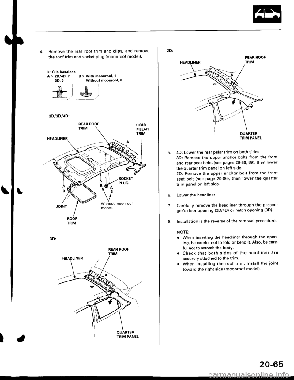
4. Remove the rear roof trim and clips, and remove
the roof trim and socket plug (moonroof model).
>: Clip locationsA> 2DllD,7 B > With moonroof, 'l
3D.5 Without moonroof,3
[il',fEl
t% .l €E .l':: =,/ _._- ,/
2D l3D l4Dl
REAR ROOFTRIM
3D:
t
REAR ROOF
TRIM
2D:
5.
7.
OUARTERIRIM PANEL
4D: Lower the rear pillar trim on both sides
3D: Remove the upper anchor bolts from the front
and rear seat belts (see pages 20-86, 89), then lower
the quarter trim panel on left side.
2D: Remove the upper anchor bolt from the front
seat belt (see page 20-86), then lower the quaner
trim panel on left side.
Lower the headliner.
Carefully remove the headliner through the passen-
ger's door opening (2Dl4D) or hatch opening (3D).
Installation is the reverse of the removal procedure.
NOTE:
. When inserting the headliner through the open-
ing, be careful not to fold or bend it. Also, be care-
ful not to scratch the bodY.
. Check that both sides of the headliner are
securely attached to the trim.
. When installing the roof trim, install the joint
toward the right side (moonroot model)
6.
8.
20-65
Page 1299 of 2189
Glove box removal:
Remove the bolts, then remove the glove box.
>: Bolt locations,2
Installation is the reverse of the removal proceoure
Side air vent/Side defogger trim removal:
SIOE DEFOGGER TRIMSHOPTOWET_Carefully PrY rt at the
then remove it,side edge,
SIDE AIR VENTRemove the driver's dashboard lower
cover, or oPen the glove Dox,
HOOKS
then push the cliPs from each
opening by hand, and Pull it
out. Disconnect the connedors(driver's side).
HOOKS
DASH LIGHTSBRIGHTNESSCONTROLLERCONNECTOR{for some models)
CFUISE CONTROLMASTER SWITCHCONNECTOR(for some models)
Center dashboard lower covel:
1. Remove:
. Driver's dashboard lower cover
. Glove box
2. Remove the screws and bolt, then remove the cen-
ter dashboard lower cover. Disconnect the accesso-
ry socket connector'
>i Boh, screw locations
a>, 1 B>'5
A s*o.e-- I A
@;*;ry'-1'-.J _e)
3. Installation is the reverse of the removal proceoure'
(cont'd)
20-69
LOWER COVER
Page 1386 of 2189
Troubleshooting -'96 - 98 Models
From page 21-10
Check the under-hood fuse/relayDOX:N/leasure the voltage between theNo. 3 terminal of the blowermotor relay 4P socket and bodyground,
ls there baftery voltage?
Check lor an open in th€ wire:1. Turn the ignition switch ON (ll).
2. Measure the voltage betweenthe No. 4 terminal of the blow-er motor relay 4P socket andbody ground.
Repair open in tho wire betweenthe No. 17 fuss and tho blowelmotor rclay,
Check for en opon in the wire:1. Turn the ignition switch OFF.2. Check for continuity betweenthe No. 2 terminal of the blow-er motor relay 4P socket andbody ground.
Check foi an open in the wirebetwe€n the blower motor relavand body glound. lf the wiro isOK, check fo. poor ground atG{01 and G4O2.
ls there continuity?
Repair open in the BLU/WHTwire b€tween the blower motorrelav and the blower motor.
Blower Motor (cont'dl
BLOWER MOTOR RELAY 'P SOCKET
1211
tt-l_T
trv)
i
21-12
Page 1406 of 2189

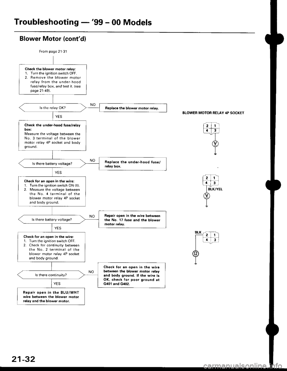
Troubleshooting -'99 - 00 Models
From page 21-31
Check the blower motor relay:1. Turn the ignition switch OFF.2. Remove the blower motorrelay from the under hoodfuse/relay box, and test it- (seepage 21'49).
Replace the blower motor relay.
Check the under-hood tuse/relaybox:Measure the voltage between theNo. 3 terminal of the blowermotor relay 4P socket and bodyground.
Check tor an open in the wire:1. Turn the ignition switch ON (ll).
2. Measure the voltage betweenthe No. 4 terminal of theblower motor relay 4P socketand body ground.
Repair opon in lhe wire betweenthe No. 17 fuse and the blowetls there battery voltage?
Check for an open in the wire:1. Turn the ignition switch OFF.2. Check for continuity betweenthe No. 2 terminal of theblower motor relay 4P socketand body ground.
Check lor an ooen in the wirebetween the blowor motor relayand body ground. It the wiie isOK, check for poor ground atG401 and G402.
ls there continuityl
Repair open in the BLU/WHTwiae between the blower motorrelay and the blower motor,
BLOWER MOTOR RELAY 4P SOCKET
21-32