2000 HONDA CIVIC Valve
[x] Cancel search: ValvePage 1205 of 2189
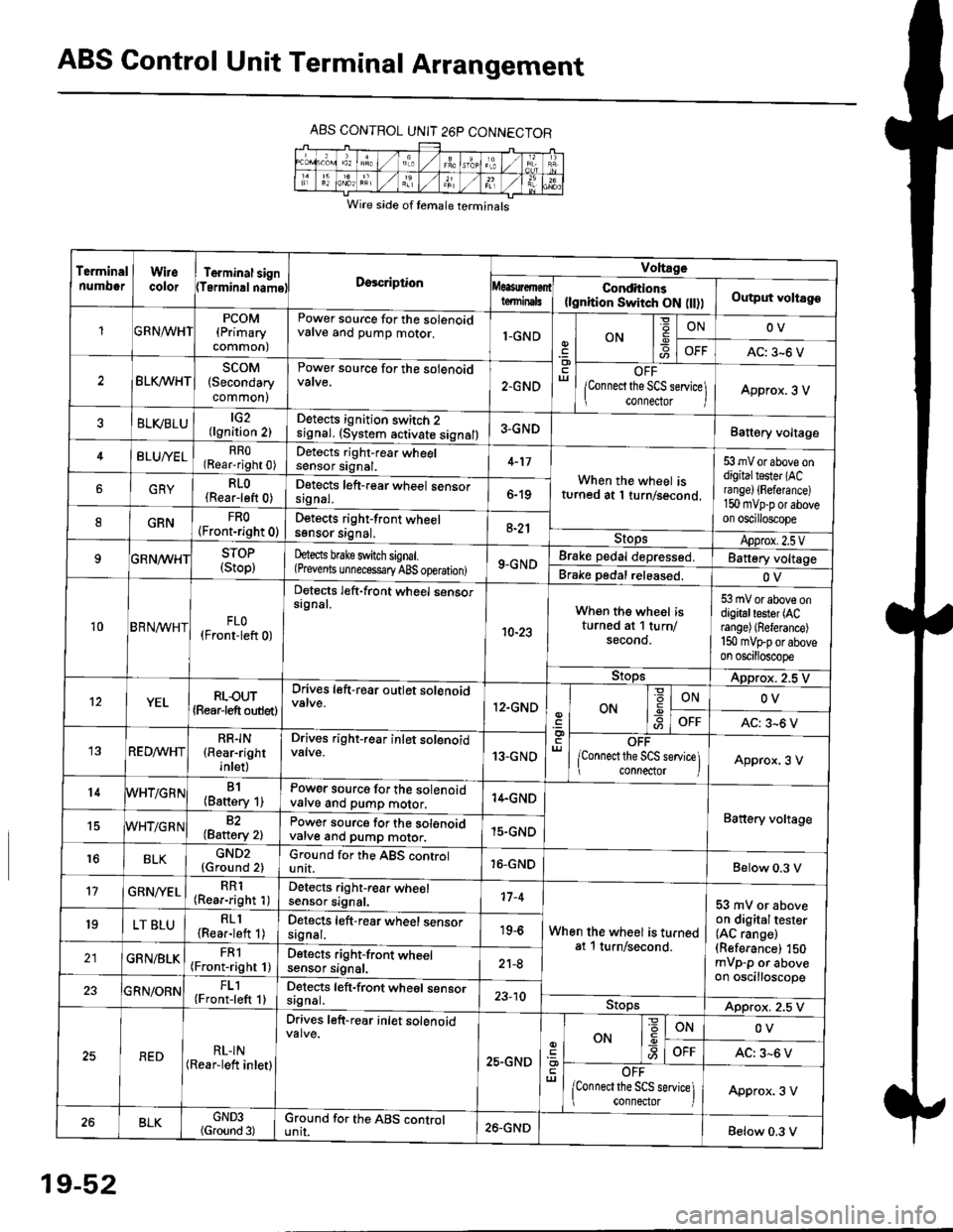
ABS Control Unit Terminal Arrangement
ABS CONTROL UNIT 26P CONNECTOR
Wire side of temale terminals
Terminalnumo0rWirecolorTerminal signTerminalnamoDgscriptionVoltage
Conditions(lgnition Switch ON flt))Output voltagoteminals
PCOM(Primary
common)
Power source for the solenoidvalve and pump motor.1-GNDON
=ONOV
AC: 3-6 V
BLK/WHTscoM(Secondary
common)
Power source for the solenoid
2.GNDOFF
lConnect the SCS service\
conneclor lApprox. 3 V
ELVBLUtG2(lgnition 2)Detects ignition switch 2
!9nal. (system activate signal)3-GNDBatt€ry voltage
BLU/YELRRO(Rear-right 0)Detects right-rear wheelsensor signal.4-17
When the wheel isturned at 1 turn/second.
53 mV or above ondigitaltester (ACra nge) {Fefera nce)150 mvp-p or aboveon oscilloscope
6GRYRLO(Rear-left 0)Detects left-rear wheel sensorsrgnal.6-19
8GRNFRO(Front-right 0)D€tects right-front wheelsgnsor srgnal,a-21StopsApprox.2.5VSTOP(Stop)hects brake switch signal.(Prevents unnecess€ry ABS operation)9-GNDBrake pedal depressed.Battery voltage
Brake pedal released.OV
10BRN^/vHTFLO(Front-left 0)
Detects left-front wheel sensorsignal.
10-23
When the wheel isturned at 1 turn/secono.
53 mV or above ondigitaltester (ACrange) (Referance)
150 mVFporaboveon oscilloscope
9!opsApprox. 2.5 V
12YELRLOUT(Rearjeft outlet)
Drives left-rear outlet solenoid
12.GNDON-9ONOV
OFFAC: 3^6 V
REDMHTRR]N(Rear-right
inlet)
Drives right-rear inlet solenoidvalve.13-GNDOFF
lconnect the SCS service]i connector IApprox. 3 V
14B1(Battery 1)Power source for the solenoidvatve and pump motor.14.GND
Battery voltage15WHT/G R N82(Baftery 2)Power source for the solenoidvarve ano pump motor.15.GND
r6BLKGND2{Ground 2)Ground for the ABS controlunit.16-GNDBelow 0.3 V
17GRN/'/ELRR1(Rear-right 1)Detects right-rear wheelsensor signal.17-4
When the wheel is turnedat 1 turn/second.
53 mV or aboveon digitaltester(AC range)(Referance) 150mVp-p or aboveon oscilloscope
19LT BLURLl(Rea.-left 1)Detects left-rear wheel sensorsagnal.19-6
GRN/BLKFRl(Front-right 1)Detects right-front wheelsensor signal.21-8
FL1(Front-left 1)Detects left-front wheel sensorsignal.23-10StopsApprox. 2.5 V
REDRL-IN(Rear-lett inletl
Drives left-r€ar inlet solenoid
25.GND
ut
ON
'6
-9ONOV
OFFAC: 3-6 V
OFF
lconnect the SCS service] connector lApprox. 3 V
BLKGND3(Ground 3)Ground for the ABS cgntrolunit.26.GNDBelow 0.3 V
19-52
Page 1206 of 2189
e\
t
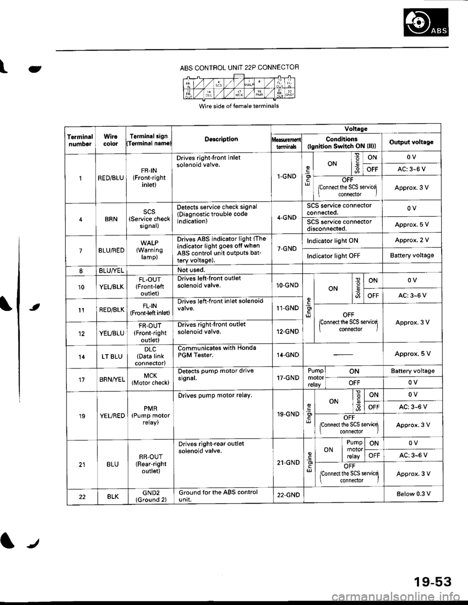
ABS CONTROL UNIT 22P CONNECTOR
Wire side of female terminals
TerminalnumbelWirocororTerminalsignDe3cription
Volt.ge
ConditionE(lgnition Switch ON (ll)lOutput voltagolTqrminal namslterminils
RED/BLUFR-IN{Front-rightinlet)
Drives right-front inletsolenoid valve.
I-GNDriJ
ON-9ONOV
OFFAC: 3-6 V
OFF
/Connect the SCS servicq
connector IApprox. 3 V
BRNscs(Service checksignal)
Detects service check signal
{Diagnostic trouble codeindication)4-GND
SCS service connectorconnected.OV
SCS service connectordisconneded.Appro)(. 5 V
7BLU/RED(Warning
ramp)
Drives ABS indicator light (The
indicator light go€s off when
ABS control unit outputs bat-
tery volta9e),
7-GND
Indicator light ONApprox, 2 V
Indicator light OFFBattery voltage
8BLU/YELNot used.
10YEUBLKFL.OUT{Front-leftoutlet)
Drives left-front outletsolenoid valve.10-GNOON
ONOV
OFFAC:3-6 V
11RED/BLKFLIN{Front-l€ft inlet)
Drives left-front inlet solenoid11-GNDOFF
lconnect the SCS servicq
connector IApprox. 3 V
YEUBLU
FR.OUT(Front-right
outlet)
Drives right-front outlet
solenoid valve.12-GNO
l4LT BLUDLC(Data linkconnector)
Communicates withPGM Tester.Honda14.GNDApprox. 5 V
17BRNA/ELMCK
lMotor check)
Detects pump motor drivesrgnal.17.GNDPumpmotorreray
ONBattery voltage
OFFOV
19YELREDPMR(Pump motorreray,
Drives pump motor relay.
19-GND
ONONOV
OFFAC: 3-6 V
OFFponnect the SCS sewicq
connedor lApprox. 3 V
BLURR-OUT(Rear-right
outletl
Drives right-rear outlel
solenoid valve.
21-GNDuJ
ON
Pumpmotorrelay
ONOV
OFFAC: 3-6 V
OFF
lconnect the SCS servicq
connedor )Approx. 3 V
22BLKGND2(Ground 2)Ground for the ABS controluntt.22-GNDBelow 0.3 v
19-53
Page 1207 of 2189
Troubleshooting Precautions
ABS Indicator Light
I The ABS indicator light comes on when the ABS control unit detects a problem in the system. However, even thoughthe system is normal, the ABs indicator light can come on, too, under the following conditions. To determine theactual cause of the problem, question the customer about the problem, taking the following conditions into consider-ation.
. Signal disturbance
. Wheel soin
. Only drive wheels rotate. Battery voltage fluctuates
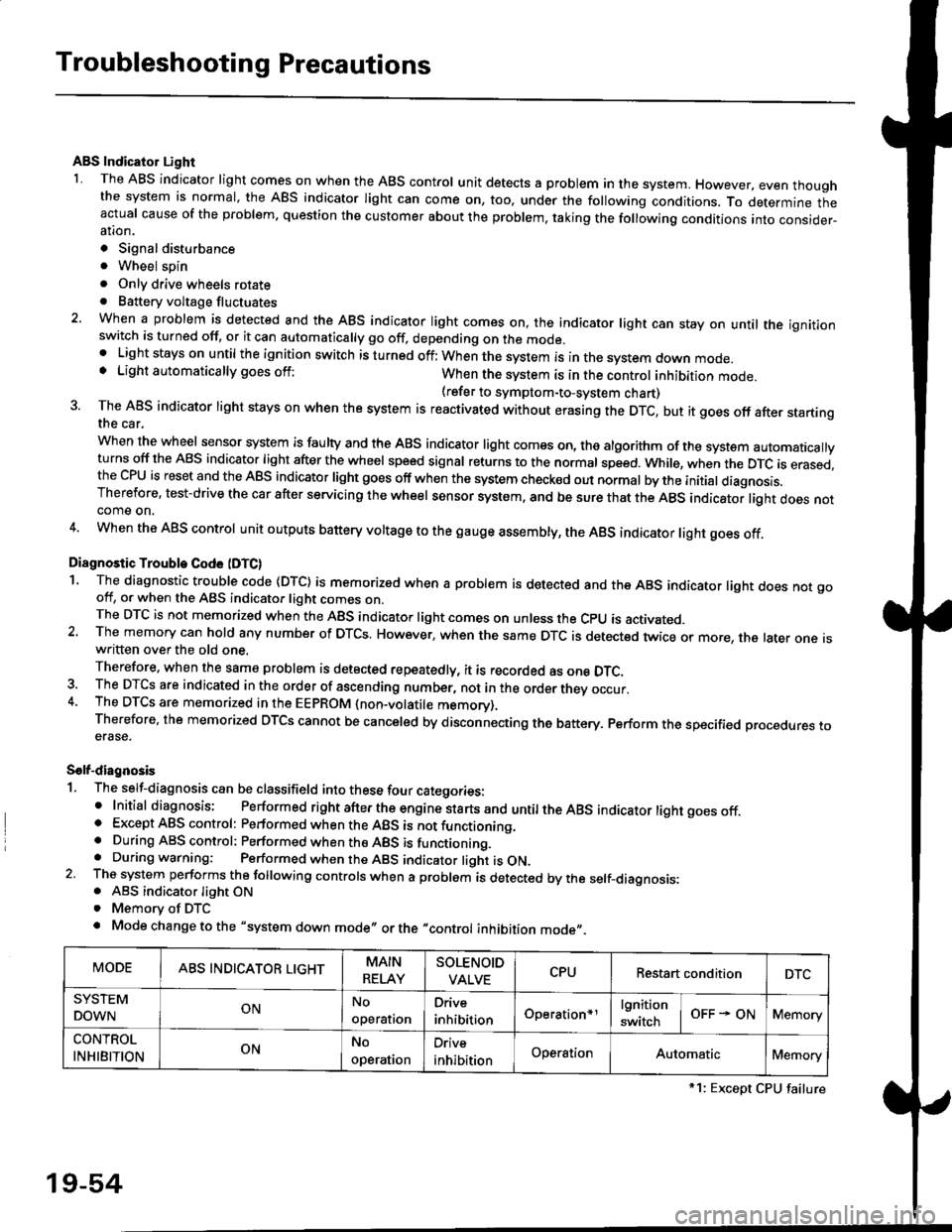
2. When a problem is detected and the ABS indicator light comes on, the indicator light can stay on untat the ignitionswitch is turned off, or it can automatically go off, depending on the mode.. Lightstayson until the ignition switch isturned off;When the system is inthesvstem down mode.o Light automatically goes off:When the system is in the control inhibition mode.(refer to symptom-to-system chart)3 The ABS indicator light stays on when the system is reactivated without erasing the DTC, but it goes off after startingthe car.
when the wheel sensor system is faulty and the ABS indicator light comes on, the algorithm of the system automaticallyturns off the ABS indicator light after the wheel speed signal returns to the normal speed. while, when the DTC is erased,the CPU is reset and the ABS indicator light goes off when the system check€d out normal by the initial diagnosis.Therefore, test-drive the car after servicing the wheel sensor system, and be sure that the ABS indicator light does notcome on.
4. When the ABS control unit outputs battery voltage to the gauge assembty, the ABS indicator light goes off.
Diagnostic Trouble Code (DTC)
1. The diagnostic trouble code (DTC) is memorized when a problem is detected and the ABS indicator light does not gooff, or when the ABS indicator light comes on.The DTC is not memorized when the ABs indicator right comes on unress the cpU is activated.2. The memory can hold any number of DTCs. However, when the same DTc is detected twice or more, the later one iswritten over the old one.
Therefore. when the same problem is detected repeatedly, it is recorded as one DTC.3. The DTCS are indicated in the order of ascending number, not in the order thev occur.4. The DTCS are memorized in the EEpROM {non-volatile memorv}.Therefore, the memorized DTCS cannot be canceled by disconnecting the battery. perform the specified orocedures toerase.
Solf-diagnosis
1. The self-diagnosis can be classifield into these four categories:' Initial diagnosis; Performed right after the engine sta rts and untiltheABs indicator light goes off.o Except ABS control: Performed when the ABS is not functioning,. During ABS control: Performed when the ABS is functioning.. During warning: Performed when the ABS indicator light is ON.2 The system performs the following controls when a problem is detected by the self-diagnosis:. ABS indicator light ON. Memory of DTC
. Mode change to the "system down mode,, or the "control inhibition mode,,.
MODEABS INDICATOR LIGHTMAIN
RELAY
SOLENOID
VALVECPURestart conditionDTC
SYSTEM
DOWNONNo
operal|on
Drive
inhibitionOperation+rlgnition
switchOFF - ONMemory
CONTROL
INHIBITIONONNo
operat|on
Orive
inhibitionOperationAutomaticMemory
*1: Except CPU failure
19-54
Page 1208 of 2189
tJ
t\
Kickback
1. The motor operates when the ABS is functioning, and the fluid in the reservoir is forced out to the master cylinder
causing kickback at the brake pedal.
2. TheABScontrol unit operates the solenoid valve when the brake pedal is released afterthe initial diagnosis Youmay
hear the faint solenoid valve operation sound at this time. but it is normal.
Pump Motor
1. The pump motor operates when the ABS is functioning
2. The ABS control unit checks the pump motor operation during acceleration. You may hear the faint operation sound
at this time. but it is normal.
Brake Fluid Replacament/Air Blsading
1. Brake fluid replacement and air bleeding procedures are the same as for conventional brakes
Troubleshooting
1. The troubleshooting flowcharts explain the procedures on the assumption that the cause of the problem is still pre-
sent and the ABS indicator light is still on.
Note that troubleshooting following the flowchart when the ABS indicator light does not come on can result in incor-
rect judgment.
2. Ouestion the customer about the conditions when the problem occurred, and try to reproduce the same conditions
for troubleshooting.
self,diagnosis is made at various times such as the initial diagnosis, except ABS control. during ABS control, during
acceleraiion, during the specified vehicle speed, etc. Therefore, the symptom cannot be checked unless the check
conditions match with the problem conditions
3. When the ABS indicator light does not come on during the test drive, but the troubleshooting is performed based on
the DTC, check for the loose connectors. poor contact of the terminals, etc, before troubleshooting.
4. After troubleshooting, erase the DTC and test-drive the car. Be sure that the ABS indicator light does not come on.
5. The connector illustrations show the female connectors with a single outline and the male connectors with a double
ouflrne.
6. The connector terminal cavities containing female terminals are always numbered by looking at the connector from
the wire side. and the cavities containing male terminals are always numbered by looking at the connector from the
terminal side.
r'
19-55
Page 1212 of 2189
Le
\.t
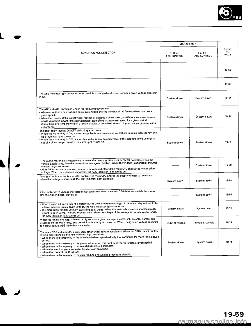
CONDITION FOR DETECTION
MANAGEI\,4ENT
FEFERTOPAGEDUNINGABS CONTFOLEXCEPTABS CONTAOL
19-60
19-62
The ABS indicator lighl cones on when vehicle is stopp€d and wheel sensor a given vohaqe does nol
19 64
The ABS indicaror comes on under th€lollowing conditions.When morethan one otwheels are a standstiland thelelocirv otthe fastest wheel reaches a
' fohen th. velocity of the faslesl wheel reaches or exceds a given sped, and it there ar€ somewh@lswhose velocity is slowe.lhan a cenain percenlage oi lh€ fast6t wheelsped for 3 given period. when rhere are lemporary open or short ctcuits ol rhe wheel sonsor' chipp€d pulser gear, orsrgnalorslJrbaaLe
19 64
The main relay repeats ON/OFF switching atalltimes.WhenthemainrelayisON,ashortt$tpulseissentloeachvalve lfthere s some dis'repa ncv, lheABS indicalor lightcomes on.. When rhe main relay is OFF, a shonl€sl pulse is s€nlto each valve lfth6 solenoid drive voltage rsout ol a qiven range, the ABS ndicalor lighl comes on19-66
'The pump nolot s activaled orc€ o' Mrce sfier every gn't'on sw'lch ON (ll) operarion whrle lte -^vchicle acLelerales lrenthemolorotivevo'taSersrhecled When lhevolla96 rs abnormar,lre Absindicaror llghl comes on.. Afte. ABS ;onl rol com pletion, the moror isswitched ofi 6nd the main CPU checks the molor dnvevoltase. when rhe vortase is abnormsl, the ABS indicato49!!!99!:l!:_-
19-68
D!rino an active motor lesl or AAS control,lhe main CPU checks ihe supplv voltage to the motor'whe;lhe vohage s abnofmal, the ABS indicator lightcomes on19,68
lirhe moror drvevoltage indicates molot operalion when the main cPU does notswilch the motoroN, rhe ABs indicaro. comes on19-64
. Wh"" " ".1"".1d ""1r. f"llure is detecred, the CPU checksth€ voltage ofthe main rel6v output lllhevohaqe is lowerthan 6 given vohage, theABS indicator light comes on. The ;ain r€lay repeats ON/OFF switching ar a!ltimss when the main rel.v is ofi, a shorl l6st pulse
is sent ro €ach valve. The CPU mon tors the reJer€nce vohage ll the vohage is out ot a g iven range'
the ABS indic.tor lightcomes on
19 71
wt'",, rt'e lgnitlon rottag" is ower or higherthan a given voltage,lhe CPU inhibils ABSlonlrolandswirches oli the ma in relaY, 6nd the ABS indicaror lig ht com€s on When the ig n ilion vohage recove'sto normal f6ng6, ABS inhibition is canceled.19.73
rimln CpU anO suU CeU ch€ck each other undercertain condnions. Whon rhe CPUS dstectthe fol'lowing discrepanaies, rhe ABS indicator light comss on. whe; rh€re is discGpancv n lhacarculated wheelspeed velocirv thar continuosJor more than a given
.i^/hen rhere is discrcoancv in the ehase informalion lhat continuesfor morerhan a given period' When rhere is discrepancY in thecalculared conlfol pa.amerer'. When thewatch dog conrrolp!lsetailslof a given penod. When th6 checkotth€ ROM tai1s.. when there is disrepancy inrhe data roading.nd wriung prcledurc ot RAM
19 7'l
tr
19-59
Page 1280 of 2189
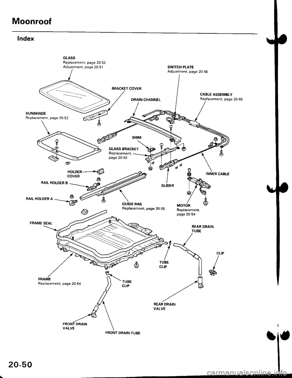
Moonroof
SWITCH PLATEAdjustment, page 20 56
REAR DRAINTUBE
Y<
/ ?'''�u8E ll /LfP ll I
U6
./w
FRONT ORAIN TUBE
CABLE ASSEMBLYReplacement, page 2O-55
Index
SUNSHADEReplacement, page 20-52
RAIL HOLDER B
RAIL HOLDER A
REAR DRAINVALVE
--:=::
0\g TNNER CAELE
20-50
Page 1285 of 2189
L
L
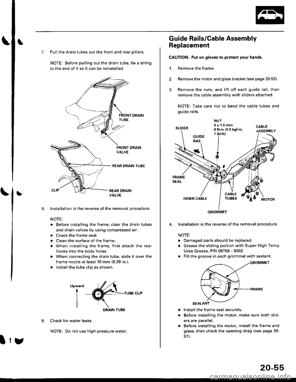
7. Pull the drain tubes out the front and rear pillars.
NOTE: Before pulling out the drain tube, tie a string
to the end of it so it can be reinstalled.
Installation is the reverse of the removal procedure.
NOTE:
. Before installjng the frame, clear the drain tubes
and drain valves by using compressed air.
. Check the frame seal.
. Clean the surface of the frame.
. When installing the frame, first attach the rear
hooks into the body holes.
. When connecting the drain tube, slide it over the
frame nozzle at least 10 mm (0.39 in.).
. Install the tube clip as shown.
UpwardI
I
I
TUBE CLIP
Check for water leaks.
NOTE: Do not use high-pressure water.
DRAIN TUBE
Ity
20-55
Guide Rails/Cable Assembly
Replacement
CAUTION: Put on gloves to protect your hands,
1. Remove the frame.
Remove the motor and glass bracket (see page 20-52).
Remove the nuts, and lift off each guide rail, then
remove the cable assembly with sliders attached.
NOTE: Take care not to bend the cable tubes and
guide rails.
Installation is the reverse of the removal procedure.
NOTE:
. Oamaged parts should be replaced.
. Grease the sliding portion with Super High Temp
Urea Grease, P/N 08758 - 9002.
. Fillthe groove in each grommet with sealant.
a
a
Install the frame seal securely.
Before installing the motor. make sure both slid-
ers are parallel.
Before installing the motor. install the frame and
glass, then check the opening drag (see page 20-
GROMMET
Page 1377 of 2189
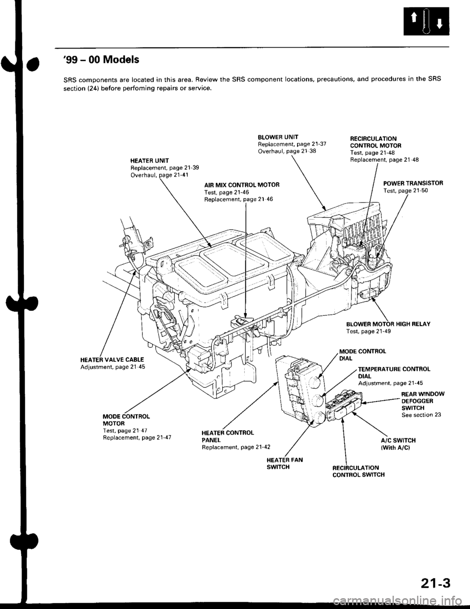
'99 - 00 Models
SRS components are located in this area, Review the SRS component locations, precautions, and procedures in the SRS
section (24) betore perfoming repairs or service.
HEATER UNITReplacement, page 21'39
Overhaul, page 21-41
BLOWEB UNITReplacement, page 21-37Overhaul, page 21 38
HEATER FANswtTcH
RECIRCULATIONCONTROL MOTORTest, page 21-48Beplacement, page 21-48
AIR MIX CONTROL MOTOBTest, page 21-46Replacement, page 21 46
BLOWERTest, page 21-49
POWER TRANSISTORTest, page 21 50
HIGH RELAY
MODE CONTROLDIALHEATER VALVE CABLEAdjustment, page 21 45TEMPERATURE CONTROLDIALAdjustment, page 21-45
REAR WINDOWDEFOGGERswtrcHSee section 23MODEMOTORTest, page 21 47Replacement, page 2 l-47A/C SWTTCH
lwith A/cl
CONTROL SWITCH
21-3