Page 1540 of 2189
Power Distribution
Circuit ldentification (cont'd)
IGN|T 0N SWTTCH (ACo)lFrom page 23-69)
*3 (or PNn -
Anernal0rVSS
HO2SEVAP conlrol canister vent shr,,l vafoeEVAP Flrge conrol so enord valveECM/PCM"
Back-!p lighls
SRS unri (VB)
i.1 :'96,98 modesr.2 : 99 mode*3 :GRY ('96-97 models):GRN (98'00 models)
sLrwHT+ Ft"t:itJY;i
BLI{WHT -}rcutcwt.,
BLKr'r{HT - Chargir! syslem trghl
InteEalei conLol unft
Shin lock soenod I r!/r\lnleiock mnlrol un I J '- '
Galge ass€mblySRS indicalor lighlABS indicrtor lghlA/Igear posilion nd€lorl d,mmino qrcu,luru6e notcaoa ) -
Inlegraled conlrcl un t
Windshield wiper molor
GRN,B-< ........- ImeEaleo cortolull| (viawndshieLd wi9el swllci)- wrrdsi erd washer .nolor(Via swrn)
Accessory power sockel (ACC)
oplioial conneclor (Acc)
Audio unil
UNDEF.DASH FUSE/REtAY BOX
No 1s (7 sA)
POWERWINDOW RELAY(To page 23-71 )
N0.25 (7.5A)
GBN/OF -- Moolroolopel relay- MOOlrOOldOSe relav
(Fusoirelay box sockel)
YEL-
(Fuse/relay box socl€l)
Y_ *,n,,*
23-70
Page 1545 of 2189
Ground Distribution
Circuit ldentification
(To
I 8an6ry ground cable
: Engine ground caue A
Primary HO2S (M/I) IEGR valve (,tffT) | {Ot6y5 engtne)EGB conrol Isllenoid va ve (vT) lwEc flessure switdr (Bl6A2engine)
vss
PSP swtch
Baaery
BLK -* bqiu"trl'ff lso",ilE o;l?f ;".,L ur,u" "ou.,,r,oo, "*'n",
Trlnsmission ho!gng
BLK
BLK
BLK
BRN/BLK
I
I
Vp?oe 23-76, 77)
'96-98 models'99-00 models 816A2, D16Y7 engines
99-00 modors D16Y5, D16Y8 engines
s,-( -i-t;lBL(- pcM Frman reray' E ) tc" 't*' tn''n''*t'''
wEC pressurc sMch(016Y5, D16Y8 engines : 98-00 models)
@
E
Efal
i Engine grcund cable B
: Engrne wire hamess
(cont'd)
23-75
El , M"in ttire hatn"."
Page 1717 of 2189

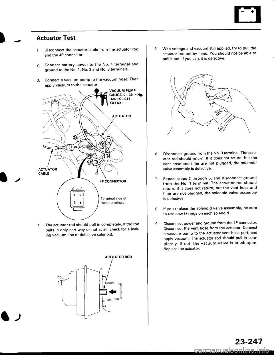
)Actuator Test
't.Disconnect the actuator cable from the actuator rod
and the 4P connector.
Connect battery power to the No 4 terminal and
ground to the No. 1, No. 2 and No. 3 terminals.
Connect a vacuum pump to the vacuum hose Then
apply vacuum to the actuator.
2.
VACUUM PUMPGAUGE,0 - 30 in.Hg.
{A973X - 041 -
xxxxxl
ACTUATOR
,lP CONNEcToR
Terminalside o{male termrnals
4. The actuator rod should pull in completely. lf the rod
pulls in only pan-way or not at all' check for a leak-
ing vacuum line or defective solenoid.
ACTUATOF ROD
l-t
23-247
5. With voltage and vacuum still applied, try to pull the
actuator rod out by hand. You should not be able to
oull it out. ll you can, it is defective
1.
Disconnect ground from the No.3 terminal. The actu-
ator rod should return lf it does not return, but the
vent hose and filter are not plugged, the solenoid
valve assembly is defective.
Repeat steps 2 through 5, and disconnect ground
from the No. 1 terminal. The actuator rod should
return. lI it does not return, but the vent hose and
filter are not plugged. the solenoid valve assembly
is defective.
It you replace the solenoid valve assembly, be sure
to use new O-rings on each solenoid.
Disconnect power and ground from the 4P connector.
Disconnect the vent hose from the actuator. Connect
a vacuum pump to the actuator vent hose port, and
apply vacuum. The actuator rod should pull in com-
pletely. lf not, the vacuum valve is stuck open.
Replace the actuator'
8.
Page 1719 of 2189
)Actuator Solenoid Test
1. Disconnect the 4P connector from the actuator'
ACTUATOR
2. Check for resistance between the terminals accord-
ing to the table.
NOTE: Resistance will vary slightly with tempera-
ture; sDecified resistance is at 70"F (20'C).
SAFETY VALVE
VACUUMVALVE
J
From VENTHOSE
+ To VACUUM
Terminalside otmale terminals
Terminal
Resistance (O) \
234
VENT SOLENOID40 600o---o
VACUUM SOLENOID30- 500G---o
SAFETY SOLENOID40- 600o---o
l)
TANK
23-249
Page 1827 of 2189

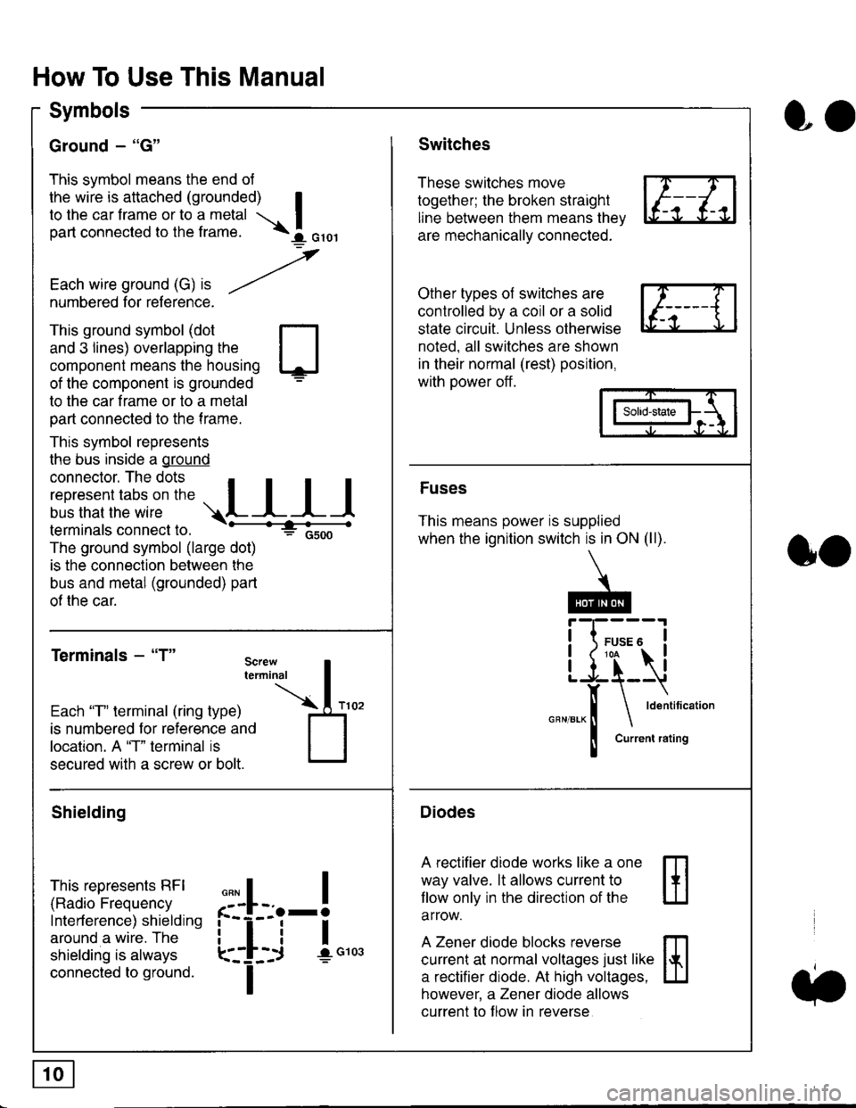
How To Use This Manual
Symbols
Ground - "G"
This symbol means the end ol
the wire is attached (grounded) Ito the car frame or to a metal I
part connected to the frame. \i oro,|
-t'
Each wire ground (G) it --/
numbered for reference.
oo
Switches
These switches move
together; the broken straight
line between them means the,
are mechanically connected.
Other types of switches are
controlled by a coil or a solid
state circuit. Unless otherwise
noted. all switches are shown
in their normal (rest) position,
with power off.
This ground symbol (dot
and 3 lines) overlapping the
component means the housing
of the component is grounded
to the car frame or to a metal
part connected to the frame.
This symbol represents
the bus inside a ground
connector. The dots I
i:l*,':1,'^:*,:"
;"
r"L I I I
terminals connect to.
The ground symbol (large dot)
is the connection between the
bus and metal (grounded) part
of the car.
Terminals - "T"
ffi
ffi
Solid-state
Fuses
This means power is supplied
when the ignition switch is in ON (ll).
Current rating
Diodes
A rectifier diode works like a one
way valve. lt allows current to
llow only in the direction of the
arrow.
A Zener diode blocks reverse
current at normal voltages just like
a rectifier diode. At high voltages.
however, a Zener diode allows
current to f low in reverse
oo
Each "T" lerminal (ring type)
is numbered for reference and
location. A "T" terminal is
secured with a screw or bolt.
Shielding
This represents RFI
(Radio Frequency
Interference) shielding
around a wire. The
shielding is always
connected to ground.
f--l;j-i",..
I
,,,,
T
Page 1840 of 2189

Ground-to-Components I ndex
f.,lONOTE: All ground wires are BLK unless otherwise noted.
GroundPageComponents or Circuit Grounded
Battery (BLKYEL)
Steering pump bracket
t+-rg ITransmission housing
l
G101
(-1)
G101
(-2)
14-2
and
14-3
ano
14-1
Powertrain or engine control module (PG1 and pG2 are BLK: LG1 and LG2 are
BRN/BLK), EGR control solenoid valve (CW, EGR valve and lift sensor (Dt6yS enginewith M,/T), Engine coolant temperature switch, pGM-Fl main relay, power steeringpressure switch (USA), Primary HO2S (D16Y5 engine with l\/,/T), Vehicle speed sensor,VTEC pressure switch (D16Y5/D16Y8 engines), CKF sensor (BRN/BLK), Transmission
control module (CYf) (Pc1 is BLK: LG1 is BRN/BLK)
Shielding betvveen the PCM or ECM and these components (all have BRN/BLK wires):
CKF sensor, TDC/CKP/CYP sensor. Primary and secondary heated oxygen sensors.
Knock sensor (CWDl6YB engine), Mainshaft speed sensor (AiT except CVT),
I Countershaft speed sensor (A/T except CVf)
Shielding between the TCM and these components (CVT) (all have BRN/BLK wires):
Drive pulley speed sensor, Driven pulley speed sensor, Secondary gear shaft
speed sensor
Powertrain or engine control module (PG1 and pG2 are BLK; LG1 and LGz are
BRN/BLK), EGR control solenoid valve (D16Y5 engine), EGR valve (Dt685), Engine
coolant temperature switch, Fuel pressure regulator shut-off solenoid valve (D1685),
PGM-FI main relay, Power steering pressure switch (USA), Vehicle speed sensor, VTECpressure switch (All except D16Y7 engine), CKF sensor (A
except 81642) (BRN/BLK)
Shielding between the PCM or ECM and these components (all have BRN/BLK wires):
CKF sensor, TDC/CKP/CYP sensor, Primary and secondary heated oxygen sensors,
Knock sensor (All except D16Y7 engine), i/ainshaft speed sensor (Arf except CW),
Countershaft speed sensor (A,/T except CVf), Drive pulley speed sensor (CW), Drivenpulley speed sensor (CVT), Secondary gear shaft speed sensor (CVf)
I Badiator fan motor, Right front parking/turn signat tight, Right headtight
G20214-4I Cruise control actuator, Left front parking/turn signal lights, Left headlight, Rear window
I washer motor, Windshield washer motor, Washer fluid level switch (,99-'00 Canada)
G401| +-o
and
14-7
Accessory power socket, Brake fluid level switch, Clutch interlock switch (M/T), Clutchswitch (lillT with cruise/D16Y5 engine with MfD, Combination wiper switch (Z wires),
Cruise control main switch, Cruise control unit, Dash lights brightness controller, Data
link connector, Daytime running lights control unit (Canada), Gauge assembly, Horn('96-'97 models), Integrated control unit, Interlock control unit (ArI), Keyless door lock
control unit ('99-'00 models with keyless), Moonroof close and open relays, Moonroof
switch, Park pin switch (A/r), Power window relay, Rear window defogger relay, Rear
window defogger switch ('96-'98 models), Steering lock, Stereo radio tuner (,96-,98
USA: LX, EX, and HX), Turn signal/hazard relay, Windshield wiper motor.....plus
everything grounded through G402
6-6
Page 1847 of 2189

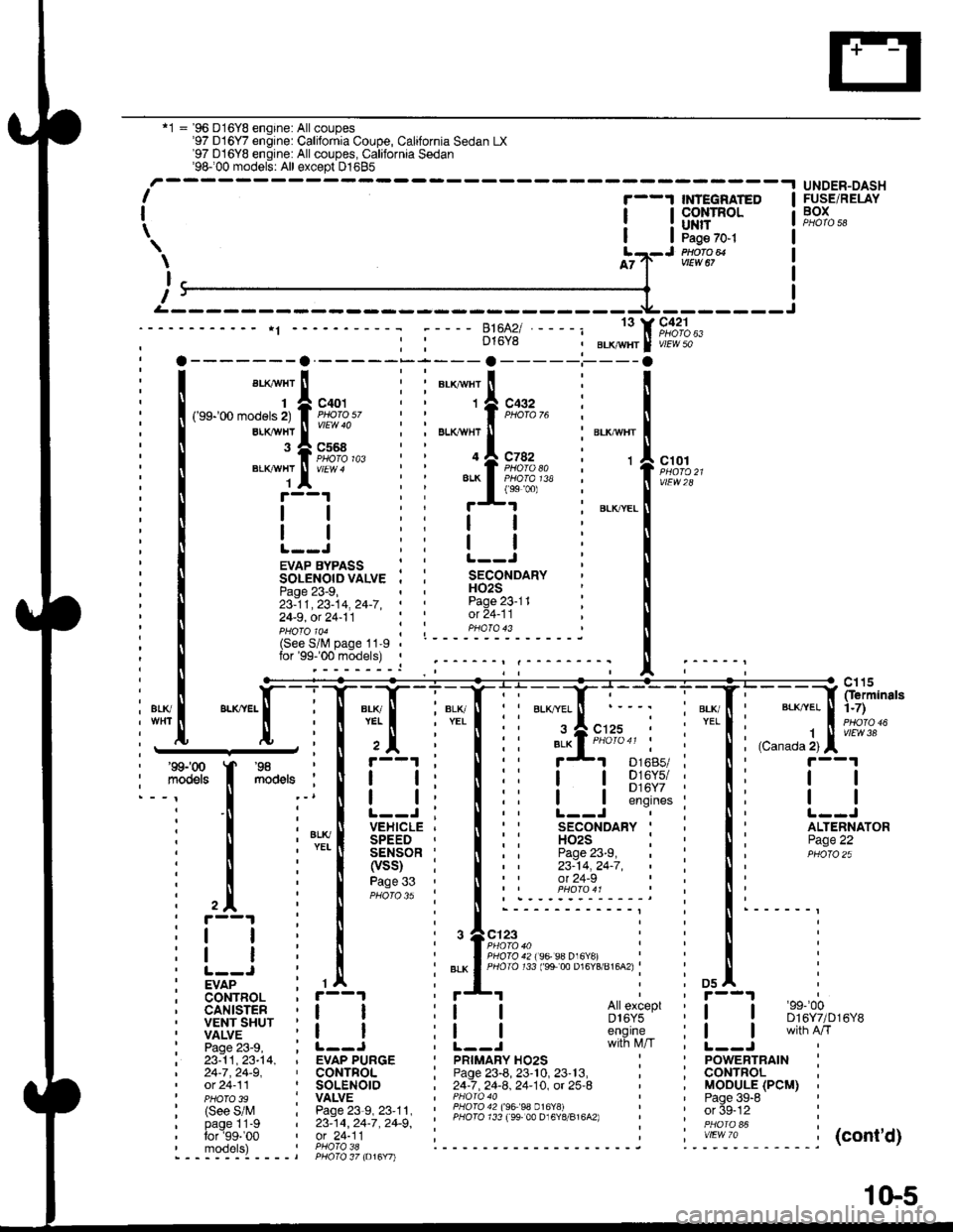
'1 = '96 D16Y8 engine: All coupes'97 D16Y7 engine: California Coupe, California Sedan LX'97 D16YB engine: All coupes, California Sedan'98100 models: All except D1685-.t UNDER-DASHI
I
\
'--1 $NEGRATED
| !s$il:'Ptlofo avtEw 67
c42'lPHO|O 63vlEW 50
ct01
vtEw28
FUSE/RELAYBOX
\
I
T
D16Y8
13
c568
ELKAYTIT
BLKAVHT
1
143
EVAP BYPASS : :SOLENOIDVALVE . ,Page 23-9,23-11,23-14,24-7,' '
24-9, ot 24-11
H02SPage 23-11ot 24-11pHoTolo4 ; ; PHoTo 43(See S/lV page 11-9lor'99-'00 models) ,
i1[
":"[-lT:T
l+Tli'::f;:r i"'{' l;;;]fip;:
I Fs'[
**,
I il i I ii !-l s];$:i i Ii t--l
i ! i'*[ iEi.;*Ti lii
'fl*-i
i li itqii-*
i l il[l?ti
lii iiii;:" i:li
i trr i I i.r^.:.'.'.'i::::;j i !' i
: i i , I i ,+e;::"," i : ! i
itI
i! | i | :".*lfigi3li;ts's"";:tg;u'u^.i : ! :
iv7"-- : rA : *'I i i osl :
; CoNTBOL , r--1
i liiit- i i_j i i_j #s,{;'i' i [__j
ffnih'*'
i 23:11,23-t4, , EVAP PURGE I pRtMARy Ho2s : ' powERTRAtN :| 24-7,24-9, ' CONTFOL ; Page 23-8, 23'10, 23'13, , ; CONTROL ,' ot 24-11 ' SOLENOIO , 24-7 .24-8. 24-10. ot 25-8 ' , MOOULE (PCM) ,' pHoTo 3s : VALVE I PHoro 40 ' ' Paqe 39-8 '
| (see s/M : Pase23-s,23'11, : ii3l311l l3;ll Pl?191,.,"^,, : ' orSe-12 :
' PHoTo 39 I vALvE | ' Paqe 39-6
: (See S/M : Page 23-9, 23'11. ' lHqI94?199 99 0.16Y!i - i ' or 5g-tz :i bi-gllt-g i zs:tq, zc-i, zc-g', ' PHoro 733 ree 00 D16Y8/816A2) i '. in6i "i i
:':1T:9' ',91"?i'l; i------ ------j ".-':-*-'1. -----j(cont'd)- - - -::-:-l - - - - t PHO\O 37 to16Y7l
1(}5
Page 1859 of 2189

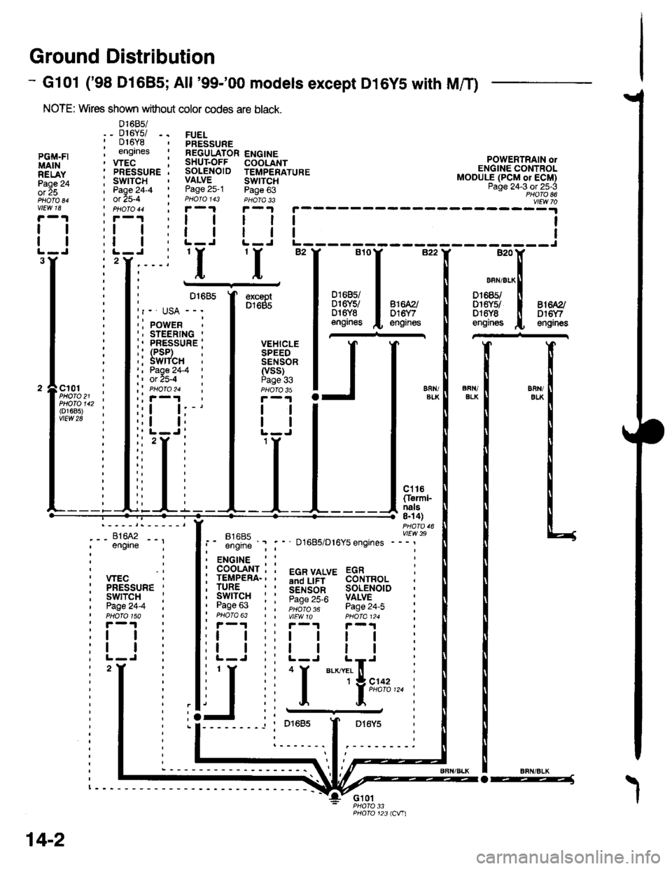
Ground Distribution
- Gl01 ('98 Dl685;All '99-'00 models except D16YS with M/T)
NOTE: Wires shown without color codes are black.
01685/_ D16Y5/ -.016Y8engrnes
.__-;,#'-_,--', engrne ;
, wEc: PRESSURE '
, swtTcH :I Page24-4 iI PHOTO 150: r -'l
:t | :
:l | :,L-J.
FUELPRESSUREREGULATOR ENGINESHUT.OFF COOLANTSOLENOID TEMPERATUREVALVE SWTTCHPage 25-1 Page 63PHOIO 143 PHOTA 33r-1F-.|
llll
lltlL-J L-J
POWERTRAIN olENGINE CONTROLMODULE (PCM or ECM)Page 24-3 ot 25-3PHOTO 86
----:y4
tl
tl
PGi,|.FIMAINRELAYPage 24ol 25
vlEw 18
tl
tl
3Y'I'I
excaptD1685
VEHICLESPEEDSENSOR(vss)Page 336FN/ELKERll/EIKcl01PHOTO 21PHOTO 142(o1685)vtEw 28
ct16Cferml-nals8n 4)
FltaFt( vttw 39t- .''iiti ' " D1685/D16Y5 engrnes ---'
t2
. ENGINE : :
i 933'?il-; i 5"T,Yf,*' 33i,"o, i
i lgfft" i I S.ir1".l^ soL€NorD :' Pase 63 : : ;;;;; - pase 24.i :' PHOTO 63 | | VtEWlO pHOIa124 ;, r-1 | , F-.t r-.r
:l | ;:l | ! | :;t | :,t | | | ;
j,f
ii T.__.,|,,,,,.
j
--
----- --l i otoas I Dr6y5 :
:------.1.--------.
14-2
o-----J