Page 1118 of 2189
Steering Gearbox
Reassembly (cont'd)
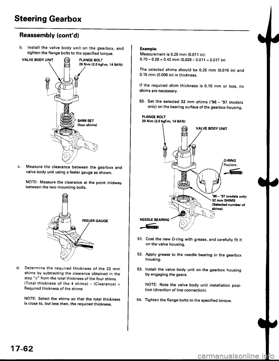
b. Install the valve body unit on the gearbox, andtighten the flange bolts to the specified torque.
VALVE BODY UNTTFLANGE BOLT20 N.m {2.0 ksl.m, 14lbI.ftl
Measure the clearance between the gearbox andvalve body unit using a feeler gauge as shown.
NOTE: Measure the clearance at the point midwaybetween the two mounting bolts.
Determine the required thickness of the 32 mmshims by subtracting the clearance obtained in thestep "c" from the total thickness of the four shims.(Total thickness of the 4 shims) - (Clearance) =
Required thickness of the shims
NOTE: Select the shims so that the total thicknessis close to. but less than, the required thickness,
17-62
54.
Example:
Measurement is 0.28 mm (0.011 in):0.70 - O.28 = 0.42 mm (0.028 - 0.011 = O.Ot7 inl
The selected shims should be 0.28 mm lO.OtO in) and0.15 mm {0.006 in} in thickness.
lf the r€quired shim thickness is 0.10 mm or less, noshims are necessarv.
50. Sot the selected 32 mm shims (,96 - ,97 modelsonly) on the bearing surface ofthe gearbox housing.
FLANGE BOLT20 N.m 12.0 ksf.m, 1l lbtftl
VALVE BODY UNIT
'96 - 37 modsl3 only:32 mm SHIMS{S.loctod numb.r of3him!l
Coat ths new O-ring with grease, and carefully fit iton the valve housing.
Apply grease to the needle bearing in the gearboxhousing.
Install the valve body unit on the gearbox housingby engaging the g€ars.
NOTE: Note the valve body unit installation posi-
tion (direction of line connection).
Tighten the flange bolts to the specified torque.
O-RINGReplace.
-A-l
NEEDLE BEARING
-R1
51.
EA
Page 1121 of 2189
71.Connect the air tube between the right and left
boot.
lnstall the clips on the cylinder lines' then clamp the
air tube with the cliPs.
l./
CYLINDER LINE A
CLIP
l-,
lnstallation
CAUTION: Be carelul not to bend or damage the feed
line and cylinder lines when installing the gearbox'
1, Before installing the gearbox, slide the rack all the
way to right.
2. Install the mounting cushion on the steering gear-
DOX.
Install the pinion shaft grommet, then insert the pin-
ion shaft up through the bulkhead.
NOTE: Align the notch in the pinion shaft grommet
with the tab on the valve housing.
Install the mounting bracket over the mounttng
cushion, then installtwo gearbox mounting bolts'
MOUNTING BRACKET
cusHroN
39 N.m(4.0 kgj m, 29 lbtftlNOTE: Install the bracket
with the arrow Pornllngtoward the front.(cont'd)
17-65
Page 1175 of 2189
Master Cylinder/Brake Booster
IRemovaUlnstallation
CAUTION:
. Be care{ul nol to bend or damage the brake lines when
rsmoving the mastsr cYlinder.
. Do not soill brakefluid on the vehicle; it may damage
the paint; if brake fluid does contact the paint, wssh
it off immediatelY with water'
. To prevent spill3, cover the hose ioints with rags or
shop towels.
9. Remove the four booster mountlng nuts
10. Pull the brake booster forward until the clevis is
clear of the bulkhead.
11. Remove the brake booster from the engine com-
panmenr.'12. Install the brake booster and master cylinder in the
reverse order of removal.
CAUTION:
. When connecting the brake lines. make sure
that there is no inte erence between the brake
lines and oth6r Parts.
r Be careful not to bend or damage the brake lines
when installing the master cylinder.
NOTE: lf replacing the master cylinder or brake
booster, check and adiust the pushrod clearance
be{ore installing the master cylinder (see page 19-221'
Fill the master cylinder reservoir, and bleed the
brake svstem (see Page 19-7).
After installation. check the brake pedal height and
brake pedal tree play (see page l9-5) and adjust if
necessary.
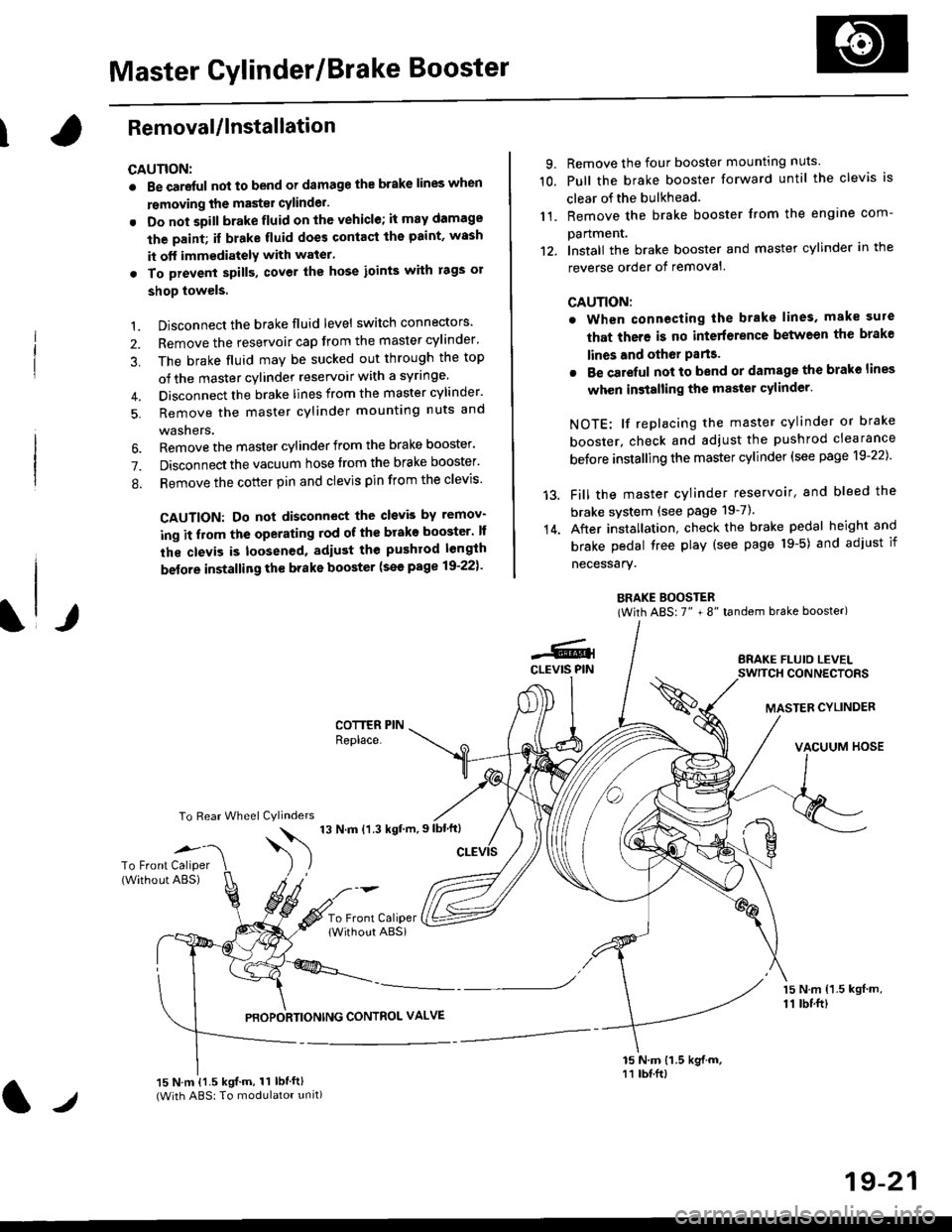
BRAKE BOOSTER(With ABS: 7" + 8" tandem brake booster)
BRAKE FLUIO LEVELSWITCH CONNECTORS
MASTER CYLINDER
VACUUM HOSE
1.
2.
3,
5.
Disconnect the brake fluid level switch connectors'
Remove the reservoir cap from the master cylinder'
The brake fluid may be sucked out through the top
of the master cylinder reservoir with a syrlnge.
Disconnect the brake lines from the master cylinder'
Remove the master cylinder mounting nuts and
washers.
\l/
6. Remove the master cylinder from the brake booster'
7. Disconnect the vacuum hose trom the brake booster'
8. Remove the cotter pin and clevis pin from the clevis'
CAUTION: Do not disconnect the clevb by remov-
ing it from the operating rod of the brako booster' lf
the clevis is loosened, adiust the pushrod length
before installing th€ brake booster (see page 19-221'
COTTER PINReplace.
To Rear Wheel Cylinders
14.
-6.4CLEVIS PIN
To Front Caliper(Without ABS)$
t'N't'ttrnt'-''
To Front CaliperlWithout ABSi
PBOPORTIONING CONTROL VALVE
15 N.m {1.5 kgl m,11 tbtft)
15 N.m {1.5 kgif.m, 11 lbtft}(With ABS: To modulator unit)lr
19-21
Page 1177 of 2189
Brake Booster InsPection
FunctionalTest
1. With the engine stopped, depress the brake pedal
several times to deplete the vacuum reservoir, then
depress the pedal hard and hold it for 15 seconds lf
the pedal sinks' either the master cYlinder is
bypassing internally, or the brake system (master
cylinder. lines. modulator, proportioning control
valve, or caliPer) is ieaking.
2. Start the engine with the pedal depressed lf the
pedal sinks slightly, the vacuum booster is operating
normally. lf the pedal height does not vary, the
booster or check valve is faultY.
3. With the engine running. depress the brake pedal
lightly. Apply just enough pressure to hold back
automatic transmission creep. lf the brake pedal
sinks more than 25 mm (1.0 in.) in three minutes,
the master cvlinder is faulty. A slight change in
pedal height when the A'lC compressor cycles on
and off if normal. (The A/C compressor load
changes the vacuum available to the booster')
Leak Test
1. Depress the brake pedal with the engine running.
then stop the engine. lf the pedal height does not
vary while depressed for 30 seconds, the vacuum
booster is OK. lf the pedal rises. the booster is
faulty.
2, With the engine stopped, depress the brake pedal
several times using normal pressure When the
Dedal is first depressed, it should be low On con-
secutive applications, the pedal height should grad-
uallv rise. lf the pedal position does not vary, checK
the booster check valve.
l./
19-23
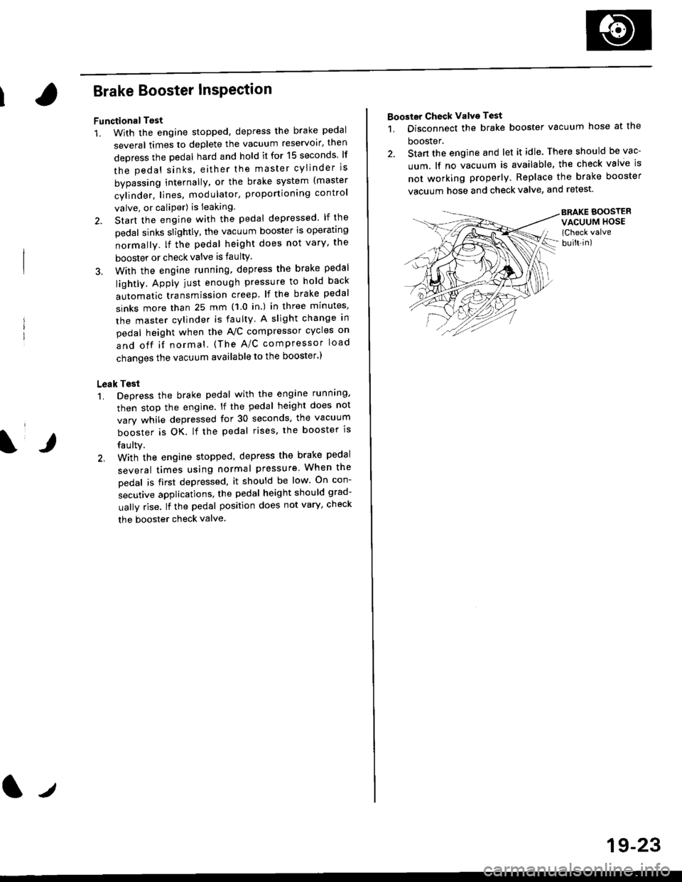
Booster Check Valve Test
1. Disconnect the brake booster vacuum hose at the
booster.
2. Stan the engine and let it idle. There should be vac-
uum. lf no vacuum is available, the check valve is
not working properly. Replace the brake booster
vacuum hose and check valve, and retest.
BRAKE BOOSTERVACUUM HOSE(Check valve
built-in)
Page 1193 of 2189
Brake Hoses/Lines
LJ
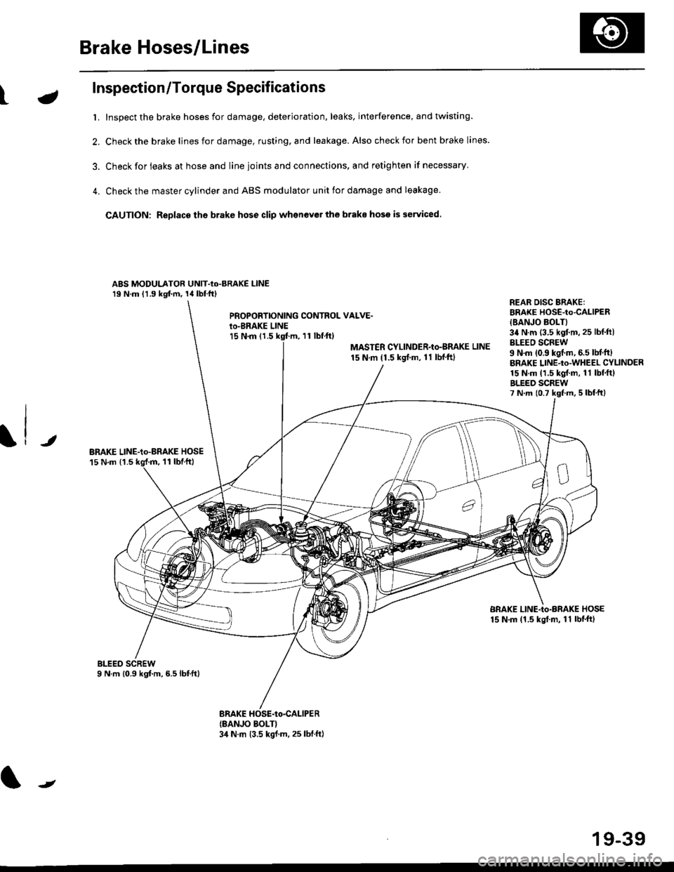
Inspection/Torque Specifications
t. Inspect the brake hoses for damage, deterioration, leaks, interference, and twisting.
2. Check the brake lines for damage, rusting. and leakage. Also check for bent brake lines.
3. Check for ieaks at hose and line ioints and connections, and retighten if necessary'
4. Check the master cylinder and ABS modulator unit for damage and leakage
CAUTION: Replace tho brake hose clip whenev€r the brake hose is serviced.
ABS MODULATOR UNIT-Io-BRAKE l-lNE19 N.m (1.9 kgf.m, 14lbl.ftl
PROPOBTIONING CONTROL VALVE.io-BRAKE LINEl5 N.m (1.511 tbf.ftl
MASTER CYLINDER-Io-BMKE LINE
15 N.m (1.5 ksrf.m, 11 lbf'ft)
REAR DISG BRAKE:BRAKE HOSE-to4ALlPER
{BANJO BOLT}34 N.m (3.5 kgtm,25 lbf ftlBLEEO SCREW9 N'm (0.9 kgf.m, 6.5 lM.ftlBRAKE LINE-to-WHEEL CYLINDER15 N.m (1.5 kgl.m, 11 lbf.ftlBLEED SCREW7 N.m {0.7 kst m, 5 lbf,ttl
JBRAKE LINE-io-aRAKE HOSE15 N.m {1.511 tbtft)
BRAKE LINE-Io-BRAKE HOSE15 N.m (1.5 kgt.m, 11 lbf'ft)
(BANJO BOLT}3,1 N.m 13.5 kgf.m, 25 lbf.ft)
J
19-39
Page 1200 of 2189
t-Operation
t
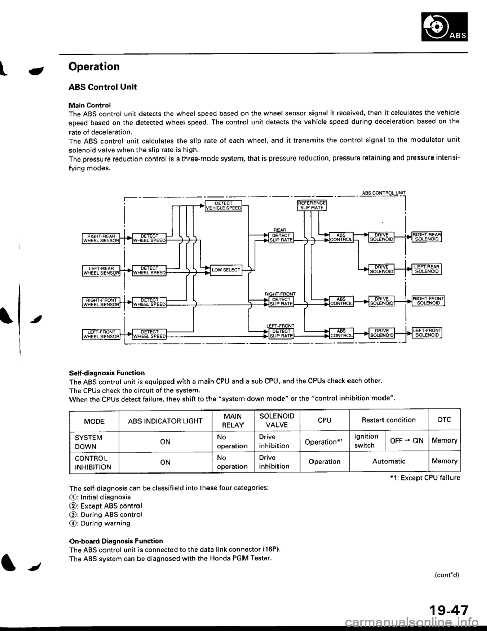
ABS Control Unit
Main Control
The ABS control unit detects the wheel speed based on the wheel sensor signal it received, then it calculates the vehicle
speed based on the detected wheel speed. The control unit detects the vehicle speed during deceleration based on the
rate of deceleration.
The ABS control unit calculates the slip rate of each wheel. and it transmits the control signal to the modulator unit
solenoid valve when the slip rate is high.
The pressure reduction control is a three-mode system, that is pressure reduction, pressure retaining and pressure intensi-
fying modes.
Self -diagnosis Funqtion
The ABS control unit is equipped with a main CPU and a sub CPU, and the CPUS check each other'
The CPUs check the circuit of the svstem.
When the CPUS detect failure, they shift to the "system down mode" or the "control inhibition mode"
The self-diagnosis can be classifield into these four categories:
O: Initial diagnosis
@: Except ABS control
@: During ABS control
@: During warning
On-board Diagnosis Funstion
The ABS control unit is connected to the data link connector {16P).
The ABS system can be diagnosed with the Honda PGM Tester.
(cont'd)
MODEABS INDICATOR LIGHTMAIN
RELAY
SOLENOID
VALVECPURestart conditionDTC
SYSTE IV
DOWNONNo
operation
Drive
inhibitionOperation*rlgnition
switchOFF + ONMemory
CONTROL
INHIBITIONONNo
operalron
Drive
inhibitionOperationAutomaticMemory
*1: Except CPU failure
/
19-47
Page 1201 of 2189
Anti-lock Brake System {ABS)
Operation (cont'dl
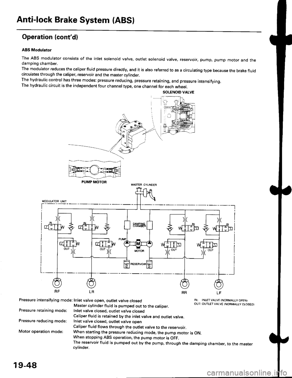
ABS Modulator
The ABS modulator consists of the inlet solenoid valve, outlet solenoid valve, reservoir, pump, pump motor and thedamping chamber.
The modulator reduces the caliper fluid pressure directly, and it is also referred to as a circulating type because the brake fluidcirculates through the caliper, reservoir and the master cylinder.The hydraulic control has three modes: pressure reducing, pressure retaining, and pressure intensifying.The hydraulic circuit is the independent four channel type, one channel for each wheel.
RF LR
Pressure intensifying mode: Inlet valve open, outlet valve closed
Pressure retaining mode:
Pressure reducing mode:
Motor operation mode:
rN: INLETVALVE {NORMALtY OpENIOUT: OUTIET VALVE {NORMALIY CTOSED)Master cylinder fluid is pumped out to the caliDer.Inlet valve closed, outlet valve closedCaliper fluid is retained by the inlet valve and outlet valve.Inlet valve closed, outlet valve oDenCaliper fluid flows through the outlet valve to the reservoir.When starting the pressure reducing mode, the pump motor is ON.When stopping ABS operation, the pump motor is OFF.The reservoir fluid is pumped out by the pump, through the damping chamber, to the mastercvlinder.
PUMP MOTOR
19-48
Page 1202 of 2189
L
Wheel Soeed and Modulator Contlo
t
OUTLETVALVE ON
OFF
INLETVALVE ON
OFF
t\,40ToR
ON
OFF
when the wheel speed drops sharply below the vehicle speed, the inlet valve closes to retain the caliper fluid pressure
When the wheel speed drops further, the outlet valve opens momentarily to reduce the caliper fluid pressure. The pump
motor starts at this time.
As the wheel speed is restored, the inlet valve opens momentarily to increase the caliper fluid pressure.
Wheel SensoJ
The wheel sensors are the magnetic contactless type
As the gear pulser teeth rotate past the wheel sensor's magnetic coil, AC current is generated The AC frequency changes
in accordance with the wheel speed. The ABS control unit detects the wheel sensor signal frequency and thereby detects
the wheel speed.
There are four wheel sensors, one for each wheel
The gear pulser has 50 teeth.
EEL SPEED
at LOW SPEEDgl
=o
GEAR PULSEBWHEEL SENSOBat HIGH SPEED
/
19-49