Page 1088 of 2189
Inspection and Adjustment
Pump Belt
NOTE: When using a new belt, first adjust the deflection
or tension to the values for the new belt, then readjust
the deflection or tension to the values for the used beltafter running engine for five minutes.
Inspection
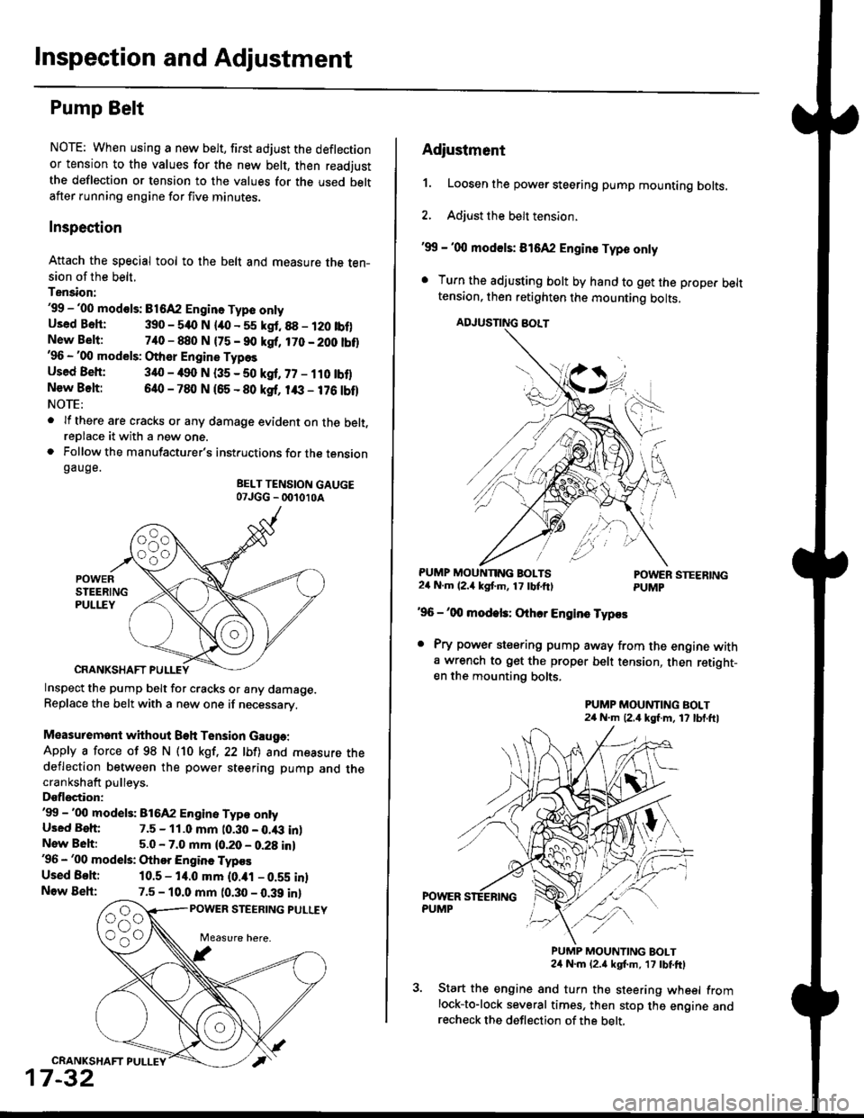
Attach the special tool to the belt and measure the ten-sion of the belt.
Tension:'99 -'00 mod€ls: B1642 Engin. Type onlyUsed Bsh: 390 - 540 N lao - 55 kgt.88 - 120 tbf)New Belt:740 - 880 N {75 - 90 kgf, 170 - 200 tbt}'96 - '00 models: Other Engine Types
Used Beh: 340 - 490 N (35 - 50 kgf, 77 - ilO tbflNew Belt:640 - 780 N 165 - 80 ksf, 1& - 176 tbf)NOTE:
. lf there are cracks or any damage evident on the belt,reDlace it with a new one.. Follow the manufacturer's instructions for the tensiongauge.
BELT TENSION GAUGE07JGG _ 001010A
Inspect the pump belt for cracks or any damage.Replace the belt with a new one if necessary.
Measuremont without Beh Tension Gauga:
Apply a force of 98 N (10 kgt,22 lbfl and measure thedeflection between the power steering pump and thecrankshaft pulleys.
Dsflectior:'99 -'00 model3: 816A2 Engine Typ€ ontyUsed Beh: 7.5 - 11.0 mm t0.30 - 0.43 inlNew Beh:5.0 - 7.0 mm (0.20 - 0.28 in)'96 - '00 models: Othor Engine Typos
Used Behi 10.5 - 14.0 mm (0.ial - 0.59 inlNow Beh:7.5 - 10.0 mm (0.30 - 0.39 inl
POWER STEERING PULUY
CRANKSHAFT PULLEY
17-32
Adiustment
1. Loosen the power steering pump mounting bolts.
2. Adjust the belt tension.
'99 - '00 mod€ls: 816A2 Engin€ Typo only
. Turn the adjusting bolt by hand to get the proper belttension, then retighten the mounting bolts,
ADJUSNNG BOLT
PUMP MOUNNNG BOLTS24 N.m (2.4 kgf'm, 17 tbtftlPOWER STEERINGPUMP
'96 -'00 modek: Othcr Engins Typos
. Pry power steering pump away from the engine witha wrench to get the proper belt tension, then retight-en the mounting bolts.
PUMP MOUNTING BOLT24 N.m (2,4 kgf.m, 17 lbl.ftl
PUMP MOUNTING BOLT24 N.m {2.a kgt m, 17 tbtftl
Start the engine and turn the steering wheel fromlock-to-lock several times, then stop the engine andrecheck the deflection of the belt,
Page 1096 of 2189
Power Steering Pump
RemovaUlnstallation
NOTE: Eefore disconnecting the hoses from the pump,
Dlace a suitable container under the vehicle.
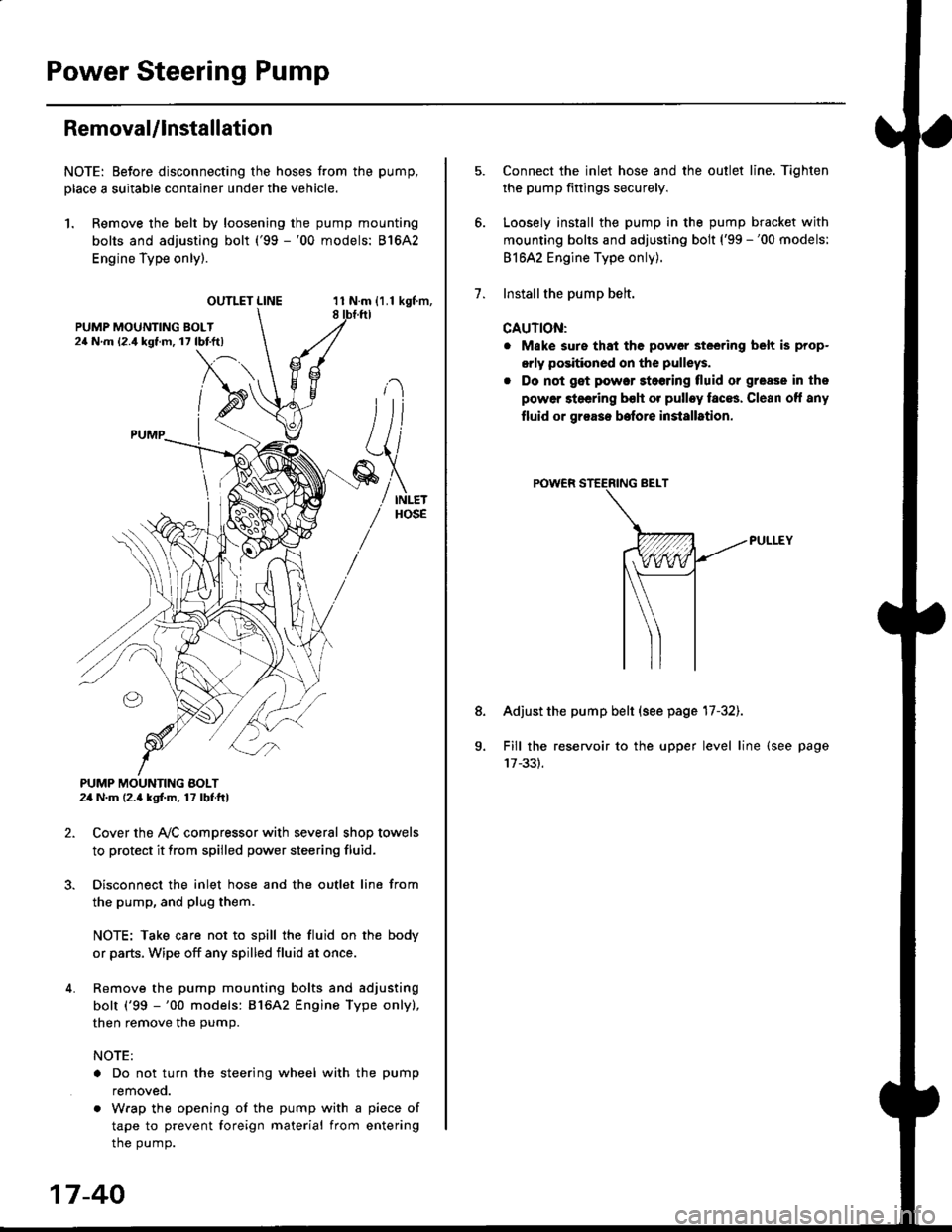
1. Remove the belt by loosening the pump mounting
bolts and adjusting bolt ('99 -'00 models: 81642
Engine Type only).
OUTLET LINE11 N.m {1.1 kgf'm,8
L
PUMP MOUNTING BOLT24 N.m (2.4 kgl.m, 17 lbf ft)
2. Cover the Ay'C compressor with several shop towels
to protect it from spilled power steering fluid.
3. Disconnect the inlet hose and the outlet line from
the pump, and plug them.
NOTE: Take care not to spill the fluid on the body
or parts, Wipe off any spilled fluid at once.
4. Remove the pump mounting bolts and adjusting
bolt ('99 -'00 models: 816A2 Engine Type only),
then remove the pump.
NOTE:
. Do not turn the steering wheel with the pump
removeo.
. Wrap the opening of the pump with a piece of
tape to prevent foreign material from entering
the pump.
17-40
1.
8.
Connect the inlet hose and the outlet line. Tiqhten
the pump fittings securely.
Loosely install the pump in the pump bracket with
mounting bolts and adjusting bolt ('99 -'00 models:
81642 Engine Type only).
Installthe pump belt.
CAUTION:
. Make sure that the power steering belt is prop-
orly positioned on the pulleys.
. Do not get power stoering tluid or grease in the
power steering bsh or pulley faces. Clean off any
fluid or grease before installrtion.
Adjust the pump belt (see page 17-32).
Fill the reservoir to the upper level line (see page
Page 1097 of 2189
Disassembly
CAUTION: The power steering components are made of aluminum. Avoid damaging the components during assembly.
NOTE:
. Ctean the disassembled parts with a solvent, and dry them with compressed air. Do not dip the rubber parts in a sol-
vent.
. Alwavs replace the O-rings and rubber seals with new ones before assembly.
. Apply recommended power steering fluid to the parts indicated in the assembly procedures'
. Do not allow dust, dirt, or other foreign materials to enter the power steering system.
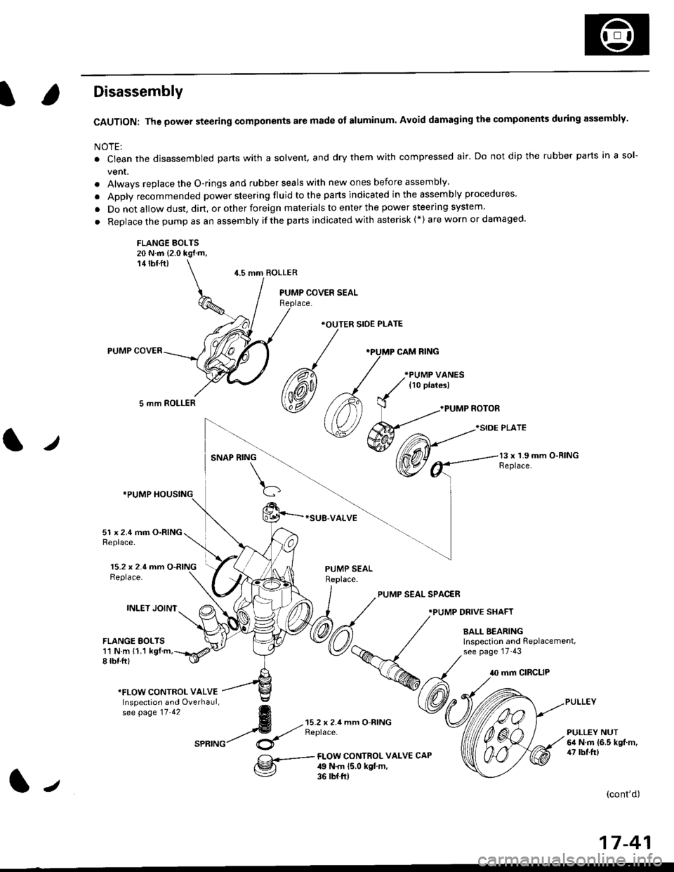
. Replace the pump as an assembly ifthe parts indicated with asterisk (*) are worn or damaged'
FLANGE BOLTS20 N.m {2.0 kgf.m,14 rbf ft)
5 mm ROLLER
4.5 mm ROLLER
*OUTER SIOE PLATE
*SUB-VALVE
.PUMP NOTOR
}SIDE PLATE
l,/SNAP RING13 x 1.9 mm O-RINGReplace.
15.2 x 2.4 mm O-RINGReplace.
INLET JOINT
51 x 2.4 mm O-RINGReplace.
FLANGE BOLTS11 N m 11.1 kgf.m,8 rbf.ftl
PUMP SEALReplace.
PUMP SEAL SPAC€R
.PUMP DRIVE SHAFT
BALL BEARINGlnspection and RePlacement,see page 17-43
10 mm CIRCLIP
*FLOW CONTROI- VALVEInspection and Overhaul,se[ pase tt.tz g
4 --{;'rX!;'seatuc/ $
mm O-RINGPULLEY NUT6il N.m {6.5 kgf.m,47 tbf.frlFI-OW CONTROL VALV€ CAP49 N.m {5.0 kgt m,36 rb{.ft)
(cont'd)
17-41
J
Page 1098 of 2189
Power Steering Pump
Disassembly (cont'dl
2.
't.Drain the fluid from the pump.
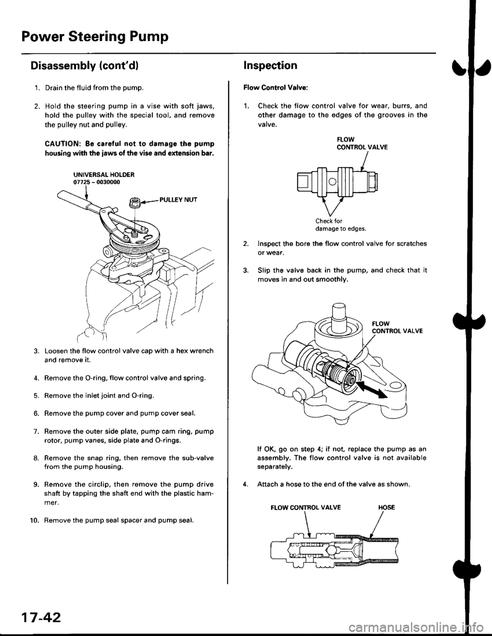
Hold the steering pump in a vise with soft jaws,
hold the pulley with the special tool, and remove
the pulley nut and pulley.
CAUTION: Be careful not to damage the pump
housing with the iaws of the vise and extension bar.
UNIVERSAL HOLDER
Loosen the flow control valve cap with a hex wrench
and remove it.
4. Remove the O-ring, flow control valve and spring.
5. Remove the inlet joint and O-ring.
6. Remove the pump cover and pump cover seal.
7. Remove the outer side plate, pump cam ring, pump
rotor, pump vanes, side plate and O-rings.
8. Remove the snap ring, then remove the sub-valve
from the pump housing.
9. Remove the circlip, then remove the pump drive
shaft by tapping the shaft end with the plastic ham-
mer.
10. Remove the pump seal spacer and pump seal.
17-42
Inspection
Flow Control Valve:
1. Check the tlow control valve for wear. burrs, and
other damage to the edges of the grooves in the
vatve,
FLOWCONTROL VALVE
Check fordamage to edges.
Inspect the bore the flow control valve for scratches
or wear.
Slip the valve back in the pump, and check that it
moves in and out smoothly.
lf OK, go on step 4; if not, replace the pump as an
assembly. The flow control valve is not available
separately.
Attach a hose to the end of the valve as shown.
FLOW CONTROL VALVE TIOSE
4.
Page 1102 of 2189
Power Steering Pump
Reassembly (cont'dl
Coat the O-ring with power steering fluid, and
install it into the grooves in the inlet joint.
Install the inlet joint on the pump housing.
'11 N.m (1.1 kgt.m,8 |bnft)
Install the pulley as shown below, then loosely
install the pulley nut. Hold the steering pump in a
vise with soft jaws.
CAUTION: Be car€ful not io damage the pump hous-
ing with the jaws ot the vise.
15.2 x 2.4Replace.-
EI
17-46
21. Hold the pulley with the specialtool, and tighten the
pulley nut.
UNIVERSAL HOLDERPULLEY NUT64 N.m {6.5 kgf.m,
Check that the pump turns smoothly by turning thepulley by hand.
Page 1454 of 2189
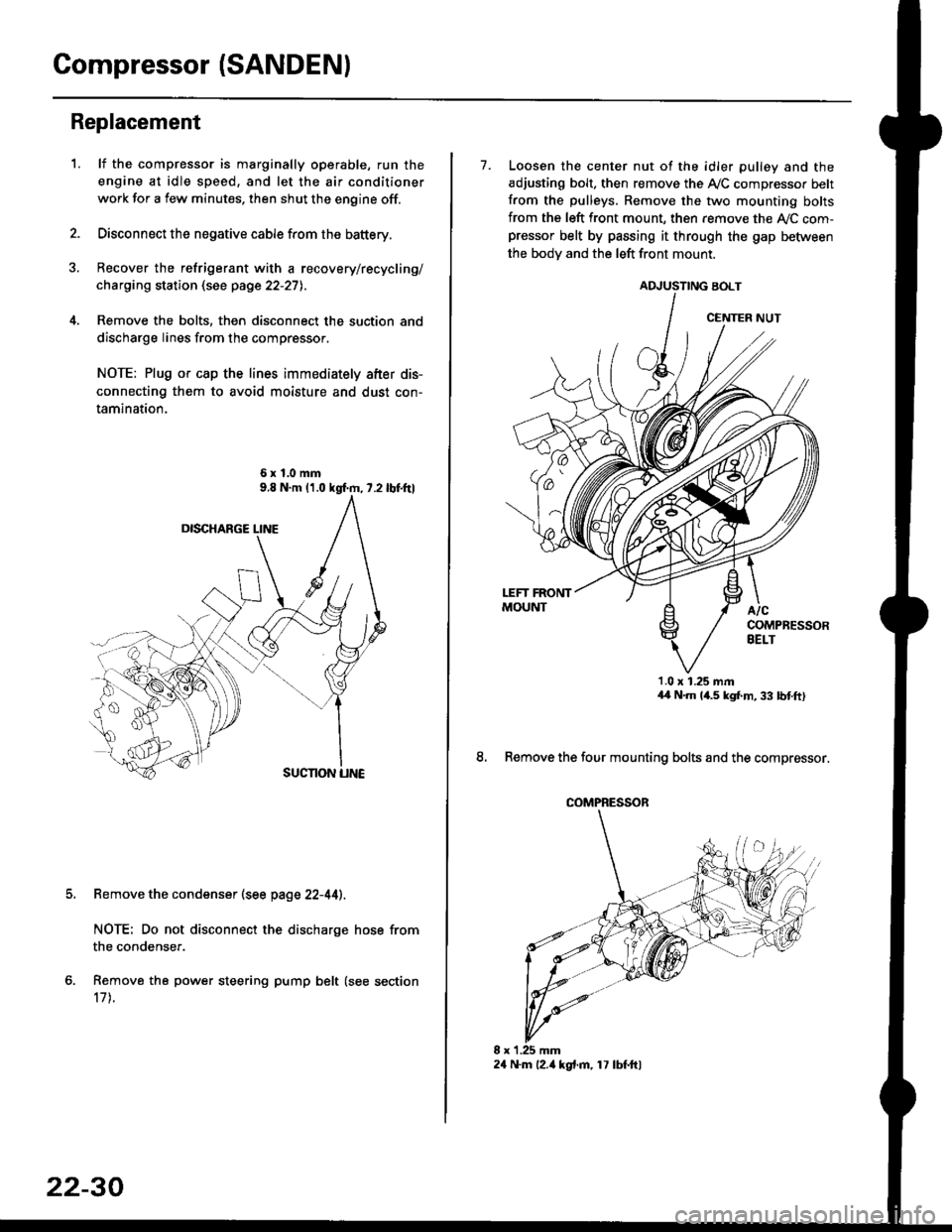
Compressor (SANDENI
Replacement
1.lf the compressor is marginally operable, run the
engine at idle speed, and let the air conditioner
work for a few minutes. then shut the engine off.
Disconnect the negative cable from the battery.
Recover the refrigerant with a recovery/recycling/
charging station (see page 22-27l..
Remove the bolts, then disconnect the suction and
discharge lines from the compressor.
NOTE: Plug or cap the lines immediately after dis-
connecting them to avoid moisture and dust con-
tamination.
6xl.0mm
Remove the condenser (see page 22-44).
NOTE: Do not disconnect the discharge hose from
the condenser.
Remove the power steering pump belt (see section
17 t.
22-30
24 N.m l2.ia kgt.m, 17 lbf.ftl
7. Loosen the center nut of the idler pulley and the
adjusting bolt. then remove the A,/C compressor belt
from the pulleys. Remove the two mounting bolts
from the left front mount, then remove the ly'C com-pressor belt by passing it through the gap befiiveen
the bodv and the left front mount.
ADJUSTING BOLT
1.0 x 1.25 mmaa N.m 14.5 kgf,m, 33 bnft)
8. Remove the four mounting bolts and the compressor.
CENTER NUT
COMPRESSOR
Page 1456 of 2189
Gompressor (SANDEN)
lllustrated Index
CENTER NUTReplace.
<-- ARMATURE PLATElnspection, page 22-33
SNAP RING BReplace.
ROTOR PULLEYInspection, page 22-33
SNAP RING AReplace.
FIELD COILlnspection, page 22-33
sHrM(s)Replace.
COMPRESSoR ](Do not disassembte ) ---------------->l
Replacement. page 22,36
THERMAL PROTECTORReplace.Inspection, page 22-33Replacement, page 22-36
tv
i-
22-32
Page 1457 of 2189
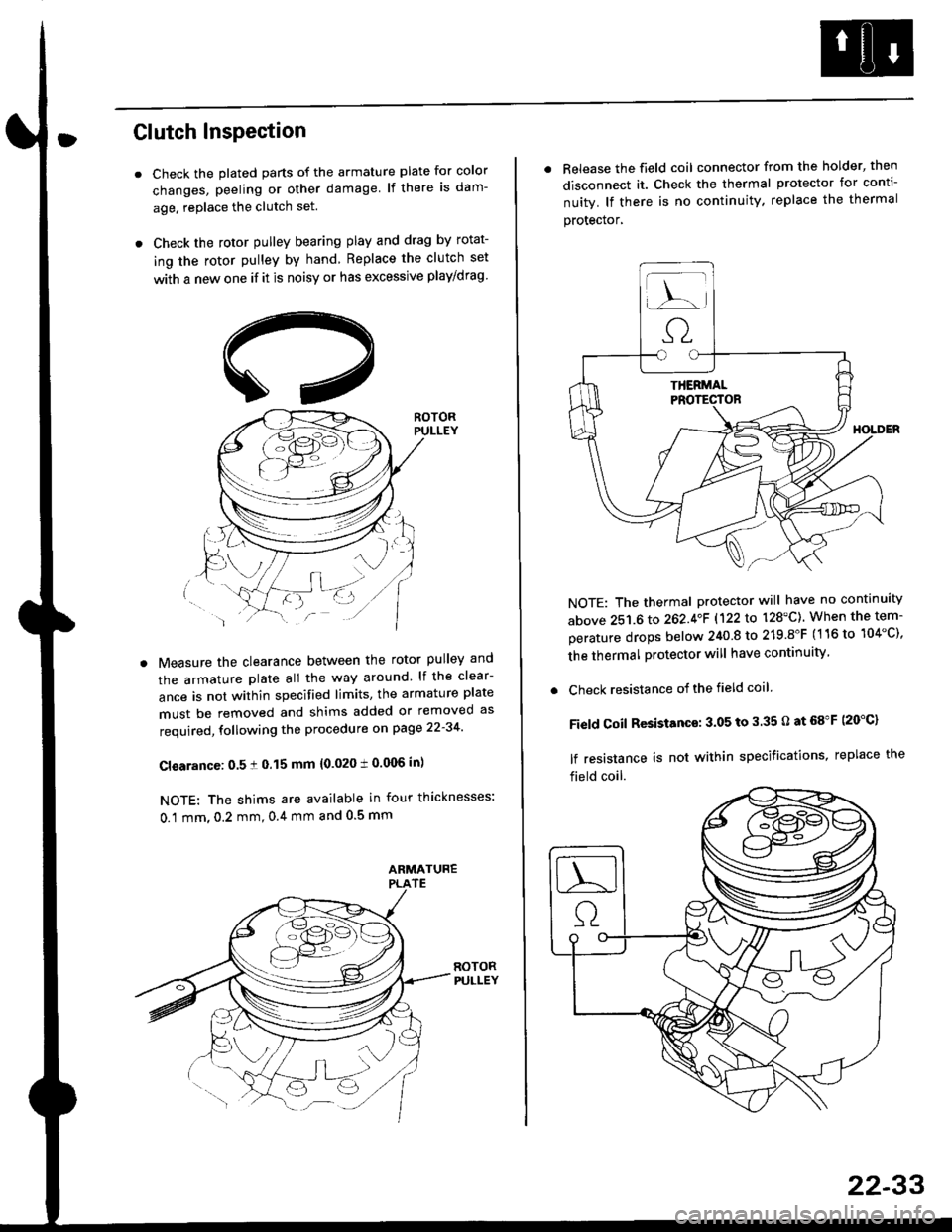
Clutch InsPection
Check the plated parts of the armature plate for color
changes, peeling or other damage lf there is dam-
age. replace the clutch set.
Check the rotor pulley bearing play and drag by rotat-
ing the rotor pulley by hand Replace the clutch set
with a new one if it is noisy or has excessive play/drag
Measure the clearance between the rotor pulley and
the armature plate all the way around lf the clear-
ance is not within specified limits, the armature plate
must be removed and shims added or removed as
required, following the procedure on page 22-34
Cl€arance: 0.5 ! 0.15 mm {0.020 t 0.006 in)
NOTE: The shims are available in four thicknesses:
0.1 mm,0.2 mm,0.4 mm and 0.5 mm
. Release the field coil connector from the holder' then
disconnect it. Check the thermal protector for conti-
nuity. lf there is no continuity. replace the thermal
protecror,
NOTE: The thermal protector will have no continuity
above 251.6 to 262.4oF 1122lo 128'C). When the tem-
perature drops below 240 8 to 219.8"F (116 to 104"C),
the thermal protector will have continuity
. Check resistance of the field coil
Field Coil Resistance: 3.05 to 3.35 O at 68"F (20"C)
lf resistance is not within specifications, replace the
field coil.
22-33