Page 932 of 2189

Troubleshooting Flowchart - Driven Pulley Speed Sensor
NOTE: Record all freeze data before you troubleshoot'
Po3sible Cause
. Disconnected dtiven PulleYso6ed sensor connector. Short or open in driven PulleYapeed sen3or wire. Faulty driven PulloY sPeod 3en-
DRIVEN PULLEY SPEEOSENSOR 2P CONNECTOR
l-_r-|1 2l
:-
t9tt
L_.1
Terminal side of male
TCM CONNECTOR I l22p)
WHT
termrnals
. OBD ll Scan Tool indicates Code
P1886.. Sell-diagnosis E indicator light
indicates Code 35.
ls the driven Pulley speed sen-
sor installed proPerlY?
M€asure Driven Pulley SP€ed Sen_
sor Resbt nce at the Sensor Con-
neclof:1. Disconnect the 2P connector
from the driven PUlley speed
sensor connectol.2. Measure the resistance ot the
driven pulley speed sensor.
ls the resistance 350 600 0?
Check Driven Pulley Speed Sen-
sor {or a Short Circuit:1. Disconnect the B (22P) connec_
tor from the TCM.2. Check for continuity between
body ground and the BB ter
minal and 89 terminal individ'
Repair sho.t in the wiles between
lhe 88 and Bg lerminals tnd the
driven pulleY 3Peed 3€nsor.
Measure Driven Pulley SPeed S€n-
sor Reistance:1. Connect the driven PulleYspeed sensor 2P connector'
2. M easu re the resistance
between the 88 and Bg terml_
nals.
Repair loos€ terminal or oPen in
the wires between the Bg and Bg
torminals and the dtiven Pulley3D6eO S6n50a,
ls the resistance 350 - 600 O?
Check lor loose TCM connector.
lf necessary, substitute a known_good TCM and rechack.
^\, REO/BLUo
12a68910
12131a15'16'171820
Wire side oI female terminals
RED/BLU]
o
WHT
1216810
12131a1516171820
14-255
Page 956 of 2189

Troubleshooting Flowchart - Drive Pulley Speed Sensor
NOTE: Record allfreeze data before you troubleshoot'
Possible Cau3€
. Disconnected diive PulleYsoeed s6n3or connectol. Short or open in drive Pull.Ysooed sonsor wire. FaultY drive PulleY spo€d sen'
301
DRIVE PULEY SPEED
SENSOR @NNEfiOR
Terminal side of male terminals
PCM CONNECTOR D (16PI
NDR SG IGRNI
Wire side o{ Iemale terminals
(cont'd)
14-279
.OBD ll Scan Tool indicates
Code Pl885.. Selt-diagnosb E indicator light
indicatos Code 34
check the drive pulleY sPeed sen-
sor installation, and check it for
damage.
ls the drive PulleY speed sen-
sor installed properly, and not
damaged?
Rein3tall or roplace and techeck
Measuro Drive PulleY Speed Sen_
sor Ro3istanco at the Sonsol
Connector:1. Disconnect the 2P conneclor
from the drive Pulley speed
sensor,2. Measure drive Pulley speed
sensor resislance at the sen-
sor connecror.
ls the resistance 350 - 600 O?
Check Drivo PulleY SP6€d Sen3o.
lor . Short Circuit:1. Disconnect the D {16P) connec-
torlrom the PCM.
2. Check lor continuity between
body ground and the D11 ter
minal and D'l2 terminal indi
vidually.
Repai. short in the wiles
between the Dll lnd D12 termi-
nals and iho drive Pull.Y speed
To page 14-280
Page 957 of 2189
Electrical Troubleshooting ('gg - 00 Models)
Troubleshooting Flowchart - Drive pulley Speed Sensor (cont,d)
PCM CONNECTOR D {16P}
Wire side of temale terminals
From page 14-279
Measure Drivo Pulley Speed Sen-sor Circuit tor an Open:1. Connect the drive pulleyspeed sensor connector,2. lvleasu re the resistancebetween the Dl1 and Dl2 ter-minals.
R6pair loose tgrminal or opan inthe wiros betwo€n tho D1,l .ndOl2 tarminrl! .nd th. drivs pul-ley speed *n3or.
ls the resistance 350 - 600 O?
Ch6ck for loose lerminal tit in thePCM connectors, ll nece3saay,substituto a known-good PCM6nd r€check.
14-280
Page 958 of 2189

Troubleshooting Flowchart - Driven Pulley Speed Sensor
NOTE: Record all freeze data betore you troubleshoot'
Po3sible Caus€
' Oisconnected driven PulleYspeed s6nlor connoctor. Short or opon in d.iven Pulleysoeed sonsol wirc. Faulty driven Pulley speed sen_
sor
DRIVEN PULLEY SPEED
SENSOR CONNECTOR
Terminal side ol male terminals
FCM CONNECTOR D If6P)
NDN IWHTI
Wire side of female terminals
(cont'd)
'OBD lt Sc.n Tool indicates
Code Pl886.. Self-diagnosb E indicator light
indicrt€. Codo 35.
Check the driven Pulley speed
sensor installation, and check it
Ior damage.
lsthe driven pulleY speed sen'
sor installed ProPerly, and not
damaged?
Boin3tall or ropl.ca and recheck.
M..sure Drivon PulloY SPoed
Sonsor Rosblanco at the S6n3or
Conn6ctori1. Disconnect the 2P connector
trom the driven PUlley sPeed
sensor,2. lveasure driven Pulley speed
sensor resistance at the sen_
sor connector.
ls the resistance 350 - 600 0?
Check Dtivon Pulloy SP€ed Sen'
sor for a Short Circuit:
1. Disconnect the D (16P) connec-
torfrom the PCM.
2. Check tor continuity between
body ground and the D10 ter'
minal and Dl6 terminal indi-
vidually.
Raoair shott in tho wi.6s
betwoon th. Dlo end D16 tormi'
nak .nd the ddven Pulley spo€d
Fo page 14'282
14-2A1
Page 959 of 2189
Electrical Troubleshooting ['gg - 00 Models)
Troubleshooting Flowchart - Driven pulley Speed Sensor (cont,dl
NON SG IRED/WHTI
Wire side of female terminals
From page l4 281
M6asure Driven Pulley SpeedSensor Circuit Ior an Op€n:1. Connect the driven pulleyspeed sensor connector,2, Measure the resistancebetween the D10 and Dl6 ter-minals.
Rgpair loose terminal or open inthe wires botwosn the Dlo and016 torminab rnd the drivon Dul-ley speed 3ensoa,
ls the resistance 350 - 600 O?
Check tor loose terminal tit in thePCM connectors, lf necessary,sub3titute a lnown-good PCMand rech6ck.
14-282
Page 969 of 2189
Drive Pulley/Driven Pulley/Secondary Gear Shaft Speed
Sensors
Replacement
CAUTION: While replacing the speed sensor, be sure not to allow dust and other foreign parliclos to enter into the trans-mission.
'1. Disconnect the connectors for the drive pulley, the driven pulley, and the secondary gear shaft speed sensor.
2. Remove the 6 mm bolt from the transmission housing, and remove the drive pulley. the driven pulley, and the sec-ondary gear shaft speed sensors.
3. Replace the O-rings before reinstalling the drive pulley, the driven pulley, and the secondary gear shaft sp€ed sen-sors.
6x1.0mm12 N.m (1.2 kgf.m,8.7 lbf.ft)
6x1.0mm12 N.m (1.2 kgt.m,8.7 tbf.ft)
DRIVEN PULLEY SPEED SENSOB
14-292
Page 972 of 2189

t.
rl,
fl,
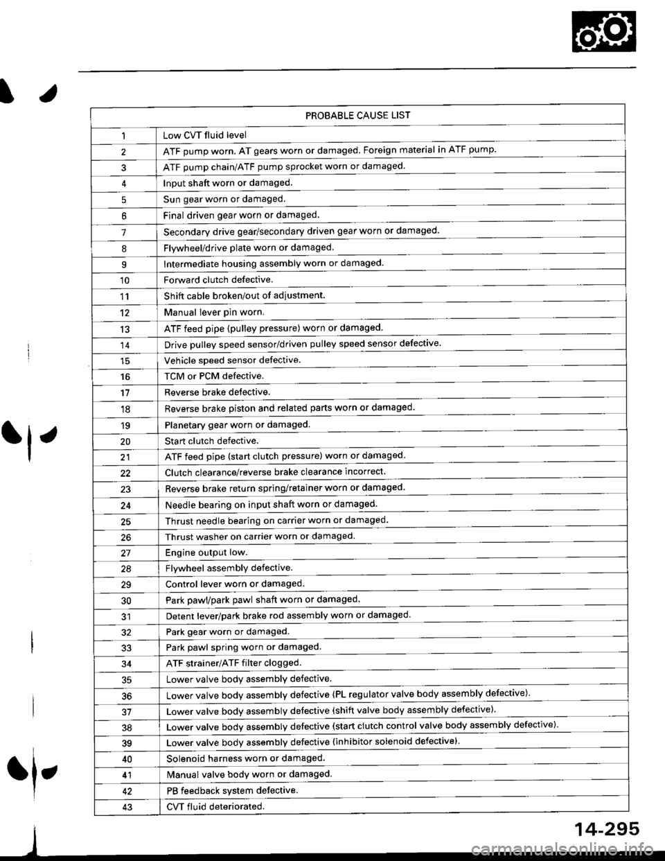
PROBABLE CAUSE LIST
Low CVT fluid level
ATF pump worn. AT gears worn or damaged. Foreign material in ATF pump.
ATF pump chain/ATF pump sprocket worn or damaged.
Input shaft worn or damaged.
Sun gear worn or damaged.
Final driven oear worn or damaqed,
Secondary drive gear/secondary driven gear worn or damaged-
5
6
1
8Flywheel/drive plate worn or damaged.
Intermediate housing assembly worn or damaged.9
'10Forward clutch defective.
Shift cable broken/out of adiustment.
M"nu"t t"uffi
ATF feed pipe (pulley pressure) worn or damaged.
Vchiclc speed sensor defective.
TCM or PCM defective.
Reverse brake detective.
1'�r
't2
13
14
16
'11
'18
1qPlanetary gear worn or damaged.
Sta rt clutch defective.
ATF feed pipe (start clutch pressure) worn or damaged
20
t't
Clutch clearance/reverse brake clearance incorrect.
23Reverse brake return spring/retainer worn or damaged
24Needle bearing on input shaft worn or damaged.
25Thrust needle bearing on carrier worn or damaged.
Thrust washer on carrier worn or damaged.
Enoine outout low.------------------------
Flvwhcel assemblv defective.
Control lever worn or damaged.
Park pawl/park pawl shaft worn or damaged
Detent lever/park brake rod assembly worn or damaged
27
29
30
32Park gear worn or damaged.
Park pawl spring worn or damaged.
ATF strainer/ATF filter clogged.
Lower valve body assembly defective.
Lower valve bodv assemblv defective (PL regulator valve body assembly defective)'
33
34
50
Lower valve bodv assembly defective (shift valve body assembly defective).
Lower valve bodv assemblv defective (start clutch control valve body assembly defective)'
39Lower valve bodv assemblv defective {inhibitor solenoid defective}
40Solenoid harness worn or damaged.
Manual valve body worn or damaged.
PB feedback system defective.
CVT fluid deteriorated.
41
43
14-295
Page 977 of 2189

Pressure Testing
. While testing, be careful of the rot8ling front wheels.
. M8k6 suro lifts, iacks, and satety stands are placed properly lsee section 11.
CAUTION:
. Before testing, be sur. the transmb3ion fluid is fillod to the propor lcvel.. Warm up the engin€ to nolmal operating tsmperature bofore testing. While t€sting, be 3ure not to allow dust and other loreign particles to onler into the transmi$ion.
1. Raise the front of the vehicle, and support it with safety stands (see section 1).
2. Set the parking brake. and block both rear wheels securely.
3. Allow the front wheels to rotate freely.
4. Warm up the engine (the radiator fan comes on), then stop arid connect a tachometer.
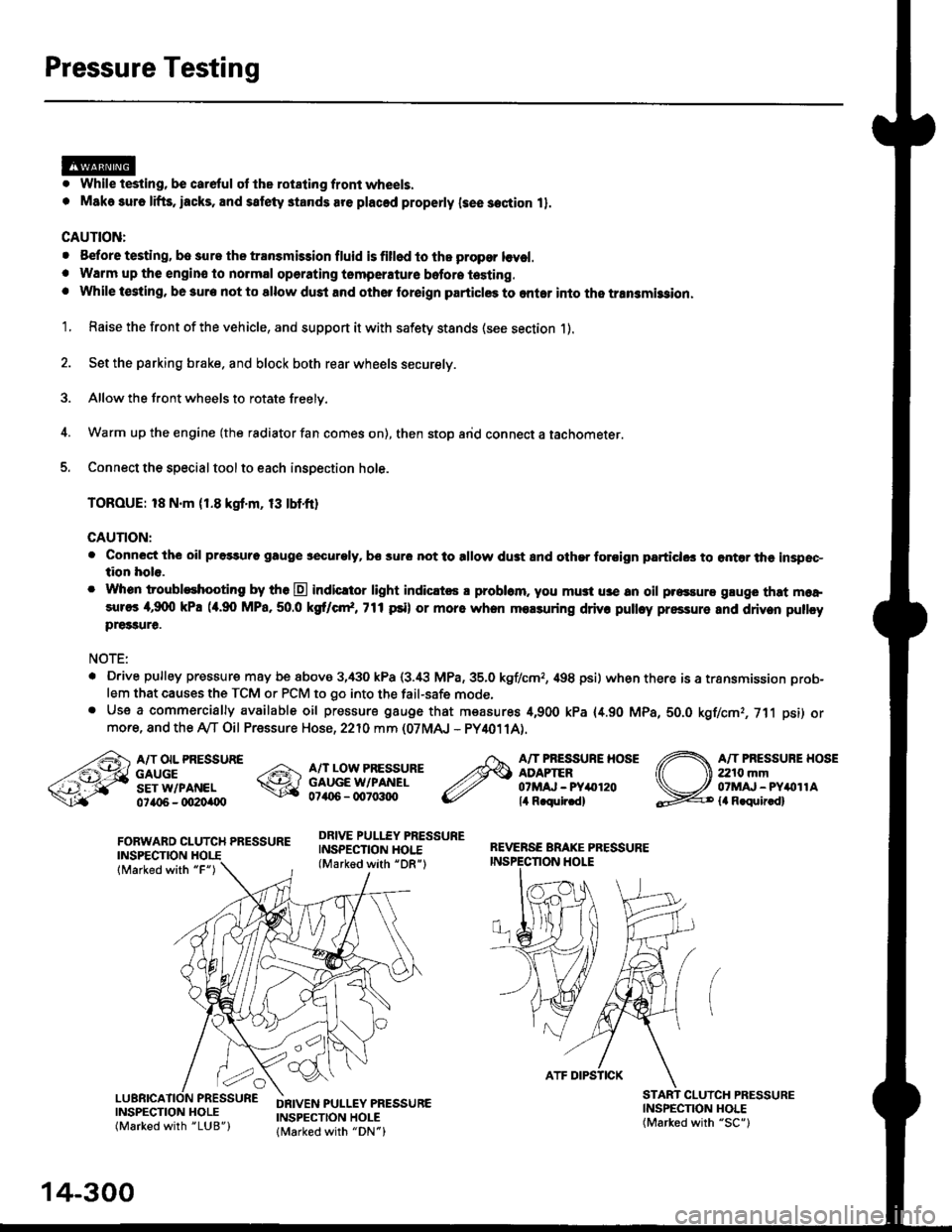
5. Connect the special tool to each inspection hole.
TOROUE: 18 N.m (1.8 kgt'm, 13 tbtfr)
GAUTION:
. Connect the oil pressuro gauge !!€curoly, bs sur6 not to allow dust and other foroign particlG3 to ontar the inspsc-tion hole.
. Whon troubleshooting by tho E indicltor light indic.t6 a problam. you mu3t u3e an oil p.essure gluge that moa,sures 4,9(X) kPa (a.90 MPa,50.0 kS cr*,771psi) or more when molsuring driv. pulley pressure and driven pullcypre33ure.
NOTE:
. D.ive pulley pressure may be above 3,430 kPa (3.i8 MPa,35.0 kgf/cmr, 498 psi) wh€n there is a transmission prob-
lem that causes the TCM or PCM to go into the fail-safe mode,. Use a commercially available oil pressure gauge that measures 4,900 kPa {4.90 MPa, 5O.O kgf/cmr, 711 psi) ormore, and the Ay'T Oil Pressure Hose, 2210 mm (07MAJ - PY4011A).
FORWARD CLUTCH PRESSUREINSPECTION
lMarked with "F")
REVERSE BRAKE PRESSUREINSPECTION I.IOLE
A/T OIL PRESSUREGAUGESET W/PANEL0ta{r6 - oO2Oi|(Xt
A/T LOW PRESSUREGAUGE W/PANEL0706 - qt7o:t{ro
DRIVE PULLEY PRESSUREINSPECTION HOI.E(Marked with "DR")
A/T PRESSURE HOSEADAPTER07MAJ - PYar'120lil R.qulr.d)
A/T PRESSUBE HOSE2210 mm07MAJ - PYitollAla R.quir.d)
(
INSPECNON HOLE(Marked with "SC")
CLUICH PRESSURE
INSPECTION HOLE(Marked with "LUB")
DRIVEN PULLEY PRESSUREINSPECTION HOLElMarked with "DN")
14-300
ATF DIPSTICK