Page 1468 of 2189

Condenser
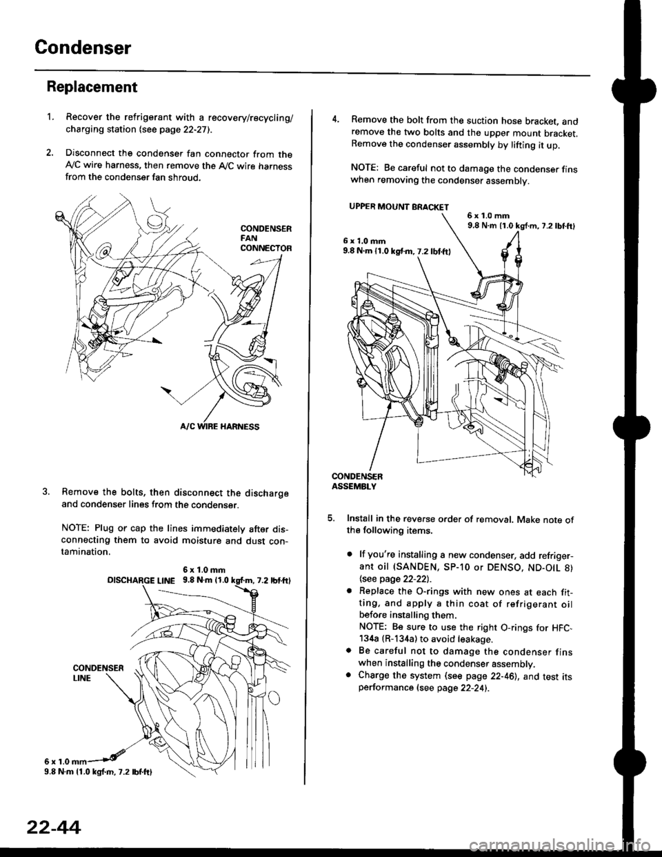
Replacement
1.Recover the refrigerant with a recovery/recycling/
charging station lsee page 22-271.
Disconnect the condenser fan connector from theAy'C wire harness, then remove the A,/C wire harnessfrom the condenser fan shroud.
Remove the bolts, then disconnect the dischargeand condenser lines from the condenser.
NOTE: Plug or cap the lines immediately after dis-connecting them to avoid moisture and dust con-tamination,
6r1.0
6x1.0mmolscHARGE L|NE 9.8 N.m 11.0
9.8 N.m 11.0 kgl.m, 7.2 lbf.ftl
22-44
4. Remove the bolt from the suction hose bracket, andremove the two bolts and the upper mount bracket.Remove the condenser assembly by lifting it up.
NOTE: Be careful not to damage the condenser finswhen removing the condenser assembly.
UPPER MOUNT BRACKET
5. Install in the reverse order of removal. Make note ofthe following items.
. lf you're installing a new condenser, add refriger-ant oil (SANDEN, SP-10 or DENSO, ND-O|L 8)
\see page 22-22l.-
. Replace the O-rings with new ones at each fit-ting, and apply a thin coat of refrigerant oilbefo.e installing them.
NOTE; Be sure to use the right O-rings for HFC,134a (R-134a) to avoid leakage.o Be careful not to damage the condenser finswhen installing the condenser assembly.. Charge the system (see page 22-46), and test itsperformance (see page 22-24i.
6x1.0mm9,8 N.m 11.0 kg{.m, 7.2lbtft}
6x1.0mm9.8 N.m 11.0 kst m, 7.2 lbf.ftl
Page 1471 of 2189

l'f .
Electrical
Special Toofs .,....................,23-2
Troubleshooting
Tips and Precautions ..............,.................... . 23-3
Five-step Troubleshooting .............. ......... . . 23-5
wire color codes ..........,23-5
Schematic Symbols ........,................... . . .. .... 23-6
Relay and Control Unit Locations
Engine Compartment ...,..................... ... .. . 23'7
Dashboard ......................23-8
Dashboard/Door ......... 23-12*Airbags ................. ....... Section 24
Air Conditioning ......... Section 21
Aftelnator ..........."""" """ 23-112
Anti-lock Brake System {ABS) Section 19*A/T Gear Position Indicator .....................,. .... ... 23-149
Automatic Transmission Svstem .... . ....... Section 14
Batterv ......... . . . ... ...... .......23-91
Blower controls .. . ... Section 2l
Charging System ....'...........23'112
Connector ldentilication and Wire Harness
Routing .................. ......23'13
Cruise Control ............,........23-240
Dash Lights Brightness Controller ............. ....... 23-180
Fan controfs "" 23'126
Fuel PumD ........ . ........ section 11
Fuses/Refay ...............,..,,.. 23'62
PGM-FI Control System ......................,....... Section 1 1
*Gauges
Circuit Diagram ....,.,.......23-131
Fuef Gauge ...........'.'.......23-142
Gauge/lndicator .. . .. 23-129
Ground Distribution .. . 23-75
Heatei controls .. . ..... Section 21*Horn................. ...............23-196
*tgnition Switch ....................23-89
lgnition System .......,.... 23-102
*lntegrated Control Unit ....................................... 23-156
fnterlock System ,........ . . , ,23-144
Lighting System . . . .. ......... 23-161
Lights, Exterior
Back-up Lights ..'............23'171
Brake Lights .................. 23'174
Daytime Bunning Lights (Canadal ............... 23'166
Front Parking Lights ......,................ .'. .......... 23-167
Front Turn Signal Lights .......... . . ............ ..,.23-167
Headtights ....".'....-... ..... 23'167
High Mount Brake Light ...................... ... .23'179
License Plate Lights ...... 23'176
Taitfights ................ .......23'171
lnterior Lights ..-.......,, . 23-142
Moonroof ..,.................,........ 23-235
Power Distribution ....... . . .23-61
Power Door Locks .......,,,. .23'251
Power Mirrors ,..............,.,...23'206
Power Relays ....... . ...... . . .. 23-86
Power Windows ............,,....23-220
Rear Window Defogger .......................... . . ... . . 23-2OO
Spark Plugs . ..... . ........ .....23-111
Slarting System ................23-93*stereo Sound Svstem ,................. ..... ... . ... ,.,.,,23'147'Supplemental Restraint System (SRS) ... . Section 24
Turn Signal/Hazard Flasher System .......'.'....-... 23-173
*Undel-dash Fuse/Relay Box ............,.................. 23-85
vehicfe soeed sensor (VSSI """" ""' 23-140+Wipers/Washers .........,.,.,...23-214
NOTE: Unless otherwise specified, references to auto-
matic transmission (Mf) in this section include the CVT.
Page 1477 of 2189
Relay and Control Unit Locations
Engine Compartment
UNDER.HOOD ABS
FUSE/RELAY BOX
CONDENSER FAN
RELAY
UNDER.HOODFUSE/RELAY BOX
MOTORRELAY
A/C COMPRESSORCLUTCH RELAY
RADIATORFAN RELAY
ELD UNIT
t:
tr
tr
uI Il I tl I
23-7
Page 1484 of 2189

Connector ldentification and Wire Harness Routing
Connector or
Terminal
Number of
CavitiesLocalionConnec{s toNotes
T,I
r2
Right side of engine compartment
Right side of engine compartment
Under-hood fuse/relay box
Starter motor
BatteryBattery positive terminal
Starter Cables
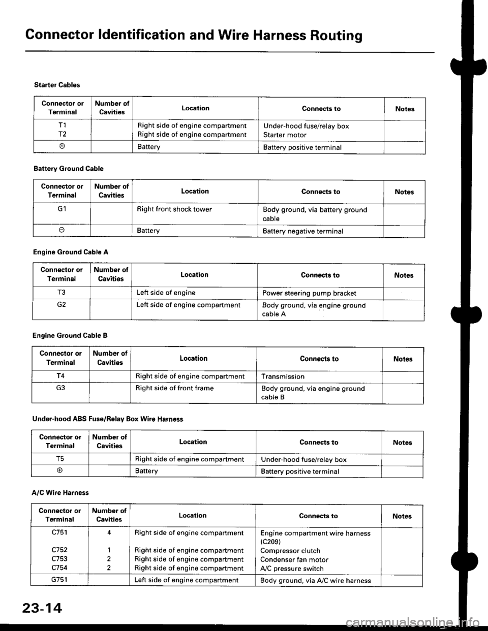
A/C Wire Harness
Battery Ground Cable
Connector or
Terminal
Number of
CavitiesLocationConn€cts toNotos
Right front shock towerBody ground, via battery ground
caDte
oBafteryBattery negative terminal
Engine Ground Cable A
Conn€qtor or
Terminal
Number ot
CavitiosLocationConnects toNoles
T3Left side of enginePower steering pump bracket
G2Left side of engine compartmentBody ground, via engine ground
cable A
Engine Ground Cable B
Connector or
Terminal
Number of
CavitiesLocationConnecls toNoles
T4Right side of engine compartmentTransmission
Right side of front frameBody ground, via engine ground
cable B
Under-hood ABS Fusa/Relay Box Wire Harness
Connector or
Tgrminal
Number oI
CavitiesLocationConneqts toNotes
T5Right side of engine compartmentUnder-hood fuse/relay box
@BaneryBattery positive terminal
Connector or
Terminal
Number of
CavitiesLocationConnects toNotes
c753
c754
1
2
Right side of engine compartment
Right side of engine compartment
Right side of engine compartment
Right side of engine compartment
Engine compartment wire harness(c209)
Compressor clutch
Condenser fan motor
A,/C pressure switch
Left side of engine compartmentBody ground, via A,/C wire harness
23-14
Page 1498 of 2189

Connector ldentification and WireHarness Routing
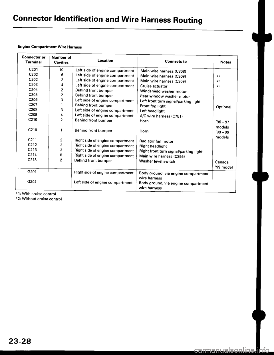
Engine Compartment Wire Harness
conneqtor of
Terminal
Number of
CavitiesLocationConnects toNotes
c201
c202
c202
c203
c204
c205
c206
c207
c208
c209
c210
c210
c211
c212
c213
c214
c215
10
6
2
2
2
1
3
2
1
2
8
Left side of engine companment
Left side of engine companment
Left side of engine companment
Left side of engine compartment
Behind front bumper
Behind front bumper
Left side of engine compartment
Behind front bumper
Left side of engine compartment
Left side of engine companment
Behind front bumper
Behind front bumper
Right side of engine compartment
Right side of engine compartment
Right side of engine compartment
Right side of engine compartment
Behind front bumper
Main wire harness (C308)
Main wire harness (C309)
Main wire harness {C309)Cruise actuator
Windshield washer motor
Rear window washer motor
Left front turn signal/parking lightFront fog light
Left headlight
Ay'C wire harness 1C751)Horn
HOrn
Radiator fan motor
Right headlight
Right front turn signal/parking lightMain wire harness (C355)
Washer level switch
Optional
'96 - 97
models'98 - 99
models
Canada'99 model
G201
G202
Right side of engine compartment
Left side of engine compartment
Body ground, via engine compartmentwire harness
Body ground, via engine compartmentwrre harness*1r With cruise control*2: Without cruise control
23-2A
Page 1528 of 2189
Gonnector ldentification and Wire Harness Routing
Heater Sub-harness A: '96 - 98 models
Connector or
Terminal
Number ot
CavitiesLocationConneqts toNotes
c7 21
c722
c723
c724
c727
7
20
2
Under left side of dash
Behind glove box
Behind glove box
Behind glove box
Behind glove box
Behind glove box
Behind glove box
Main wire harness (C440)
Mode control motor
Heater sub-harness B 1C741)Ay'C thermostat
Blower motor
Blower resister
Recirculation control motor
Heater Sub-harness B: '96 - 98 mod€ls
HEATER SUB.HARNESS A
Connoctor 01
Terminal
Number of
CavitiesLocationConngcts loNotes
c7 41
c142
c7 43
20
14
Behind glove box
Behind middle of dash
Behind middle of dash
Heater sub-harness A (C723)
Heater fan switch
Heater control panel
23-58
HEATER SUB-HARNESS B
Page 1532 of 2189
Fuses
Under-hood Fuse/Relay Box
cgo1lTo condensor fan relayl
Gr02lTo blower motor r€layl
c903*: Not usod
NOTE; View from the backside of the under-hood fuse/relav box.
[To radi.lor tan rolayl
cto5[To main wir6 harne$ (C3521]
fto l/c comprdssor]
lclutch relay I
c905lTo main wire ha.ness (C353ll
DE
tr
tr
tr
r-1
IJ
r"l17LI
n51
IJ
r"l56
LI
r"l57IJ
23-62
ITo main w;re ha.ness (C351ll
Page 1533 of 2189
(l'-
Fuse NumberAmpswire ColorComponent(s) or Circuitlsl Protect€d
4180APower distribution
4240AWHT/BLKTo ignition switch (BAT)
437.5 AWHT/REDCeiling light, data link connector, trunk light
4415 AWHT/BLKPGM-Fl main relay
Not used
4640AWHT/BLUPower window motors (via power window relay)
477.5 AWHT/BLUAudio unit, clock, TCM (CVT), ECM/PCM (VBU)
4830AWHTNo.33 (7.5 A) fuse, To combination light switch (headlight)
49Not used
5030AWHT/GRNRear window defogger (via rear window defogger relay)
cl20AWHT/GRNPower door lock control unit, moonroof motor
15 AWHT/GRNHorn system, brake lights, brake signal
10 AWHT/BLKHazard warning light, turn signal/hazard rclay
54404WHT/REDOption {+B)
5540ABLU,A/VHTBlower motor (via blower motor relay)
204WHTCondenser fan motor (via condenser fan relay)
REDl'lc compressor clutch (via IVC compressor clutch relay)
204BLVBEDRadiator fan motor (via radiator fan relay)
23-6