Page 1417 of 2189
Overhaul -'96 - 98 Models
HEATER FAN SWITCHTest, page 21-49
Air Mix Control Cable Replacomenl
1. Cut the inner cable on the lever side of the cable holder, then remove both pieces of the inner cable.
2. Using a sharp knife, cut completely through the end of the cable housing at the two locations.
3. Slidethe largesection ofthecable housing outofthe cable holder, being careful not to da mage the cable stops.
4. Carefully remove the cut pieces of the cable housing with a small flat tip screwdriver.
5. Hook the tip of the new air mix control cable to the temperature control lever, then push the cable housing into the
cable holder until it locks into place.
NOTE: After assembly, check that the temperature control lever slides smoothly through the full stroke lrom right to left.
21-43
Page 1423 of 2189
RelaysHeater Fan Switch
Test
There should be continuity between the No 1 and No. 3
terminals when power and ground are connected to the
No.2 and No. 4 terminals, and there should be no conta-
nuity when power is disconnected.
Blower motor relaY
. Blower motor high relay ('99 00 models)
,I It;€'Y )
Test -'96 - 98 Models
Check for continuity between the terminals according to
the table below.
lerminal
Position14253
OFF
1I�rJ
2o-o
3o-a
4c)-{
21-49
Page 1425 of 2189

Air Conditioning
Speciaf Tools ......'.....' 22-2
f f f ustrated f ndex ......................... ".......' 22-3
Wiring/Connector Locations'.........'.... 22'4
Description
Outfine ............ .......22-s
Circuit Diagram
'96 - 98 Models ......"..........".......'.... 22-6
'99 Modef """""""' 22-7
Troubleshooting
Symptom Chart ".'......""................. 22-8
Flowcharts
Condenser Fan .........".................,..'. 22-9
Compressor .....""" 22-12
A/C System .........'.22'17
A/C Thermostat
Test ........'.......' """'22'21
Relays
Test ....."'......... ..""'22-21
A/C Service Tips and Precautions ......22-22
A/C System Torque Specifications '...22-23
A/C System Service
Performance Test ... '."......... ".... ....'..22-24
Pressure Test Chart .................. .... "' 22-26
Recovery ...".........," 22-27
Evaporator
Replacement .....",' 22'24
Overhauf .....-.....""' 22'29
Compressor {SANDEN}
Repf acement ......'.' 22-30
fffustrated fndex ......"..................'.... 22'32
Cf utch Inspection ......... "............ ...... 22-33
Clutch Overhau I ........................ ....... 22-34
Thermal Protector Replacement .... 22-36
Relief Valve Replacement ......'..."". 22-36
Compressor (DENSO)
Repfacement ..""',' 22-37
lf lustrated Index ............................... 22-39
Clutch lnspection ............."'...... "'.... 22-40
Cf utch Overhaul .....................'......... 22-41
Ref ief Valve Replacement'..'......"'.. 22-42
A/C Compressor Belt
Adiustment ............22'43
Condenser
Repfacement .......,,22'44
A/C System Service
Evacuation ...,,,.......22-45
Charging '..........--'..22'46
Leak rest """""""'22-46
Page 1428 of 2189
Wiring/Gonnector Locations
A/C DIODE.CONDENSER FAN RELAY,COMPRESSOR CLUTCH RELAY(Located in the under,hood fuse/relay box)
COND€NSER FANCONNECTOR
COMPARTMENTWIRE HARNESS
CONNECTOR
22-4
Page 1429 of 2189

Description
Outline
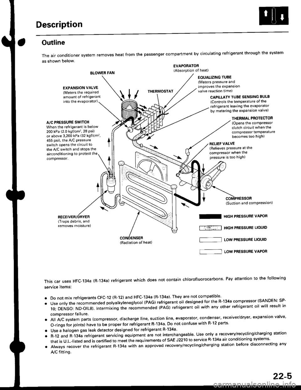
The air conditioner system removes heat from the passenger compartment by circulating refrigerant through the system
as shown below.
BLOWER FAN
EVAPORATOR(Absorption of heati
EOUALIZING TUBE(Meters pressure andimproves the expansionvalve reaction time)
into the evaporator)CAPILLATY TUBE SENSING BULB
lControls the temPerature of the
ref rigerant leaving the evaporator
by metering the expansion valve)
/\
THERMOSTAT
A/C PRESSURE SWITCH
When the refrigerant is below
200 kPa (2.0 kgtcm'�,28 Psi)or above 3,200 kPa 132 kgflcm',
455 psi), the Ay'C pressure
switch opens the circuit to
the A,/C switch and stops the
EXPANSION VALVE(Meters the requiredamount of refrigerant
airconditioning to Protect the
compressor.
RECEIVER/DRYER(Traps debris, andremoves morsturel
THERMAL PROTECTOR
{Opens the comPressorclutch circuit when the
compressor temPeraturebecomes too high)
RELIEF VALVE(Relieves pressure at the
compressor when thepressure is too high)
(Radiation of heat)
I
f-r-�-; I
(Suction and comPression,
HIGH PRESSURE VAPOR
HtGH PRESSUBE LIOUID
LOW PRESSURE LIOUID
This car uses HFC-134a (R-134a) refrigerant which does not contain chlorofluorocarbons Pay attention to the following
service items:
. Do not mix refrigerants CFC-12 (R-12) and HFC-134a (R-134a)' They are not compatible'
. Useonlythe recommended polyalkyieneglycol (PAG) refrigerant oil designedforthe R-134a compressor (SANDEN: SP-
10; DENSO: ND_OIL8). Intermixing ihe re-commended (pAG) refrigerant oil with any other refrigerant oil will result in
compressor failure.
. All A,,ic system parts {compressor, discharge line, suction line, evaporator, condenser, receiver/dryer, expansion valve'
O-rings for joints) have to be proper for refrigerant R- 134a Do not confuse with R-l2 parts'
. Use a halogen gas leak detector designed for refrigerant R-134a
. R-12 and R-134a refrigerant servacing equipment are not interchangeable. Use only a recovery/recycling/charging station
that is u,L.-listed and is certified to meet the requirements of sAE J2210 to service R-134a air conditioning systems'
. Always recover the refrigerant R-134a with an approved recovery/recycling/charging station before disconnecting any
A,/C fitting.
S]
22-5
Page 1430 of 2189
Circuit Diagram
UNDER DASHFUSE/RELAY 8OX
N0.17 (7.54)
'96 - 98 Models
UNDER.HOOD FUSEi BELAY BOX
WHT/SLU BLKYEL
BLK
+
G751
3
'o
I8LK
I
G40lG402
GNITON SWITCH
N0.41 (8rA) N0.42 (40A)
COMPBESSORCLUTCHBELAY
BLUMHT
,l
(E) i,T'
BLUi BED
A/c ITHERMOSTAI BLU/REO
CONDENSEFFAN MOTOR
*F,.X,
FAN rl
BLK
{
G401G402
HEATERswrlcH
32
22-6
Page 1432 of 2189
Troubleshooting
Symptom Chart
NOTE:
. Any abnormality must be corrected before continuing the test.. Because of the precise measurements needed. use a multimeter when testinq.. Before performing any troubleshooting procedures check:- Fuses No. 47 l7 -5 Al, No. 56 (20 A) in the under-hood fuse/relay box, and No. 17 (7.5 A) in the under_dash fuse/relavbox- Grounds No. c401, c402, G751- Cleanliness and tightness of alt connectors
SymptomRemedy
Condenser fan does not run at all.Perform the procedures in the flowchart {see page 22-9).
Compressor clutch does not engage.Perform the procedures in the flowchart lsee page 22-12).
Ay'C system does not come on (compressor and fan),Perform the procedures in the flowchan (see page 22-17).
Both heater and A,/C do not work.. '96 - 98 models-Perform the procedures in the flowchart
{see page 21-18).. '99 - 00 models-Perform the procedures in the flowchart(see page 21-35).
22-8
Page 1433 of 2189
Condenser Fan
CONDENSER FAN RELAY 4P SOCKET
JUMPERwlRE
(cont'd)
22-9
Conden3er fan does not run at all.
Check the No. 56 (20 A) fuse in the
unde.hood frJse/relaY box, and the
No. 17 (7.5 A) fuse in the under-
dash fuse/relay box.
Reolace the fuse{s), and techeck
Remove the condenser lan rclaY'
and test it (see page 22 21i
Replace the condensei fan relav.
Check the under-hood tus6/relaY
Measure the vohage between the
No. 2 terminalofthe condenser fan
relav 4P socket and bodv ground.
ls there battery voltage?
Check the condenser lan Powersupply circuit:Connect the No. 1 and No. 2 teF
minals of the condenser fan relay
4P socket with a jumper wire
Does the condenser fan run?To page 22-10
Io page 22 11