2000 FORD EXPEDITION tow
[x] Cancel search: towPage 102 of 256
Installing the third row seat
Always latch the vehicle seat to the floor, whether the seat is
occupied or empty. If not latched, the seat may cause injury
during a sudden stop.
When reinstalling a rear seat in your vehicle it must be placed in
its original position. Improper installation of the seat will prevent
correct use of the safety belts and could increase the risk of injury.
Refer to the warning label on the seat belt.
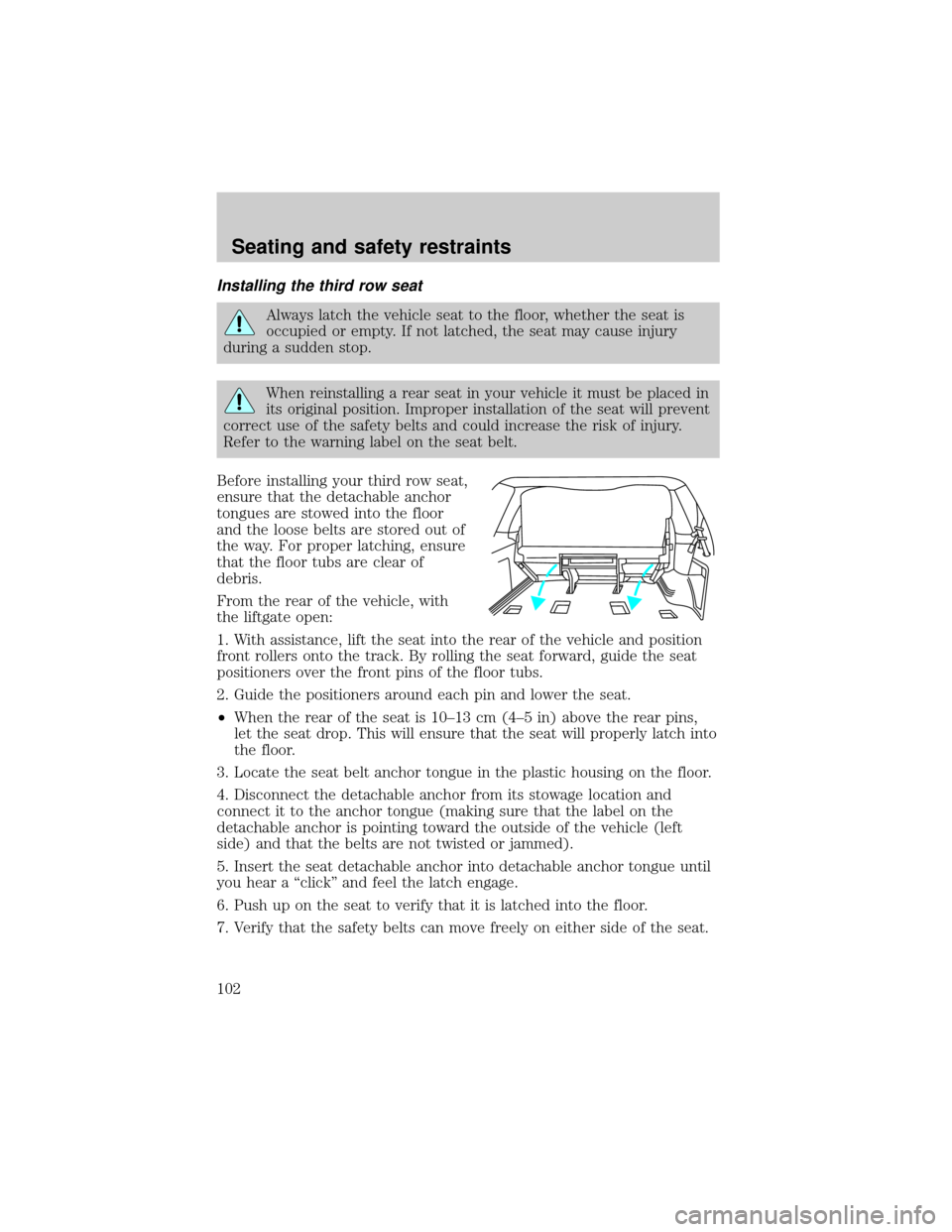
Before installing your third row seat,
ensure that the detachable anchor
tongues are stowed into the floor
and the loose belts are stored out of
the way. For proper latching, ensure
that the floor tubs are clear of
debris.
From the rear of the vehicle, with
the liftgate open:
1. With assistance, lift the seat into the rear of the vehicle and position
front rollers onto the track. By rolling the seat forward, guide the seat
positioners over the front pins of the floor tubs.
2. Guide the positioners around each pin and lower the seat.
²When the rear of the seat is 10±13 cm (4±5 in) above the rear pins,
let the seat drop. This will ensure that the seat will properly latch into
the floor.
3. Locate the seat belt anchor tongue in the plastic housing on the floor.
4. Disconnect the detachable anchor from its stowage location and
connect it to the anchor tongue (making sure that the label on the
detachable anchor is pointing toward the outside of the vehicle (left
side) and that the belts are not twisted or jammed).
5. Insert the seat detachable anchor into detachable anchor tongue until
you hear a ªclickº and feel the latch engage.
6. Push up on the seat to verify that it is latched into the floor.
7. Verify that the safety belts can move freely on either side of the seat.
Seating and safety restraints
102
Page 103 of 256
3rd row tip/stow feature
The 3rd row seat has a tip/stow feature to increase cargo space without
removing the seat from the vehicle.
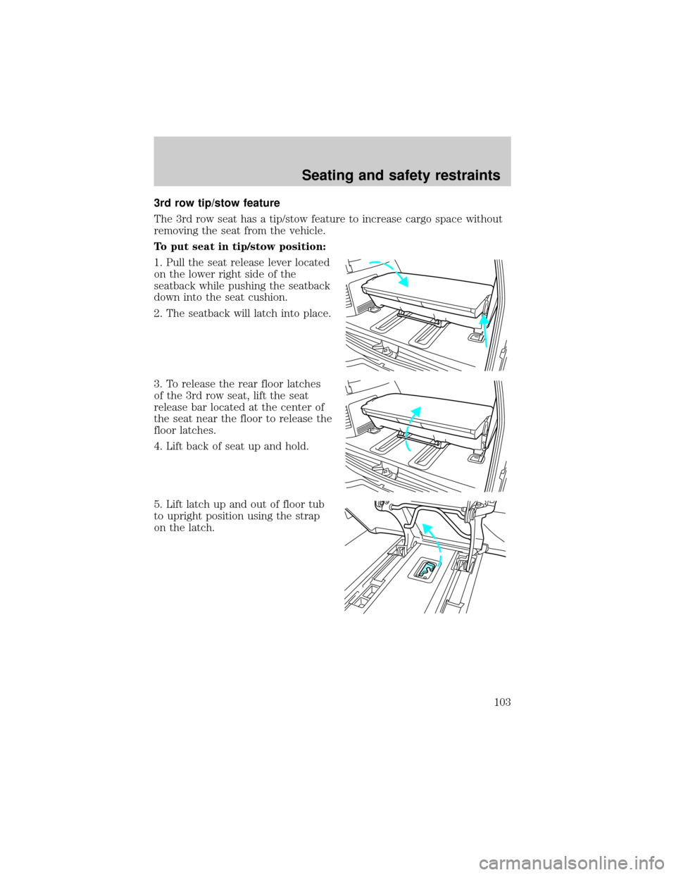
To put seat in tip/stow position:
1. Pull the seat release lever located
on the lower right side of the
seatback while pushing the seatback
down into the seat cushion.
2. The seatback will latch into place.
3. To release the rear floor latches
of the 3rd row seat, lift the seat
release bar located at the center of
the seat near the floor to release the
floor latches.
4. Lift back of seat up and hold.
5. Lift latch up and out of floor tub
to upright position using the strap
on the latch.
Seating and safety restraints
103
Page 126 of 256
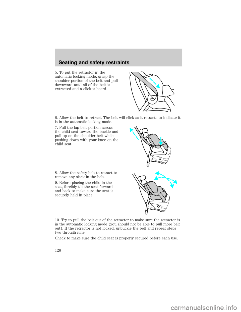
5. To put the retractor in the
automatic locking mode, grasp the
shoulder portion of the belt and pull
downward until all of the belt is
extracted and a click is heard.
6. Allow the belt to retract. The belt will click as it retracts to indicate it
is in the automatic locking mode.
7. Pull the lap belt portion across
the child seat toward the buckle and
pull up on the shoulder belt while
pushing down with your knee on the
child seat.
8. Allow the safety belt to retract to
remove any slack in the belt.
9. Before placing the child in the
seat, forcibly tilt the seat forward
and back to make sure the seat is
securely held in place.
10. Try to pull the belt out of the retractor to make sure the retractor is
in the automatic locking mode (you should not be able to pull more belt
out). If the retractor is not locked, unbuckle the belt and repeat steps
two through nine.
Check to make sure the child seat is properly secured before each use.
Seating and safety restraints
126
Page 127 of 256
Installing child safety seat in the second row center seating
position with an automatic locking retractor
1. Place the child safety seat in the center seating position.
2. In a continuous motion, pull out enough webbing from the retractor to
route the tongue through the child seat.
3. While holding the webbing to prevent it from retracting, route the
webbing through the child seat according to the child seat
manufacturer's instructions. Be sure the belt webbing is not twisted.
4. Insert the tongue into the correct buckle for that seating position until
you hear and feel the buckle engage. Make sure the buckle is latched
securely by pulling on the webbing.
5. If you have not pulled out enough webbing to reach, allow the
webbing to fully retract before attempting to pull it out again and repeat
steps 2 through 4.
6. Pull the webbing through the child seat toward the buckle while
pushing down with your knee on the child seat.
7. Allow the safety belt to retract to remove any slack in the belt. It will
make a clicking noise while doing this.
8. Before placing the child in the seat, forcibly tilt the seat forward and
back to make sure the seat is securely held in place.
9. Check to make sure the child seat is properly secured before each
use.
Installing child safety seat in the third row center seating position
(if equipped)
1. Place the child safety seat in the center seating position.
2. Route the tongue end through the child seat according to the child
seat manufacturers instructions. If the tongue will not reach the buckle,
lengthen the amount of belt by turning the tongue at a right angle to the
belt and pulling on it until it reaches the buckle. Be sure the belt
webbing is not twisted.
3. Insert the tongue into the correct buckle for that seating position
(buckle closest to the direction the tongue is coming from) until you
hear and feel the buckle engage. To tighten the belt, pull the loose end
of the belt through the tongue until all the slack is removed from the
belt. Make sure the buckle is latched securely by pulling on the webbing.
Seating and safety restraints
127
Page 139 of 256
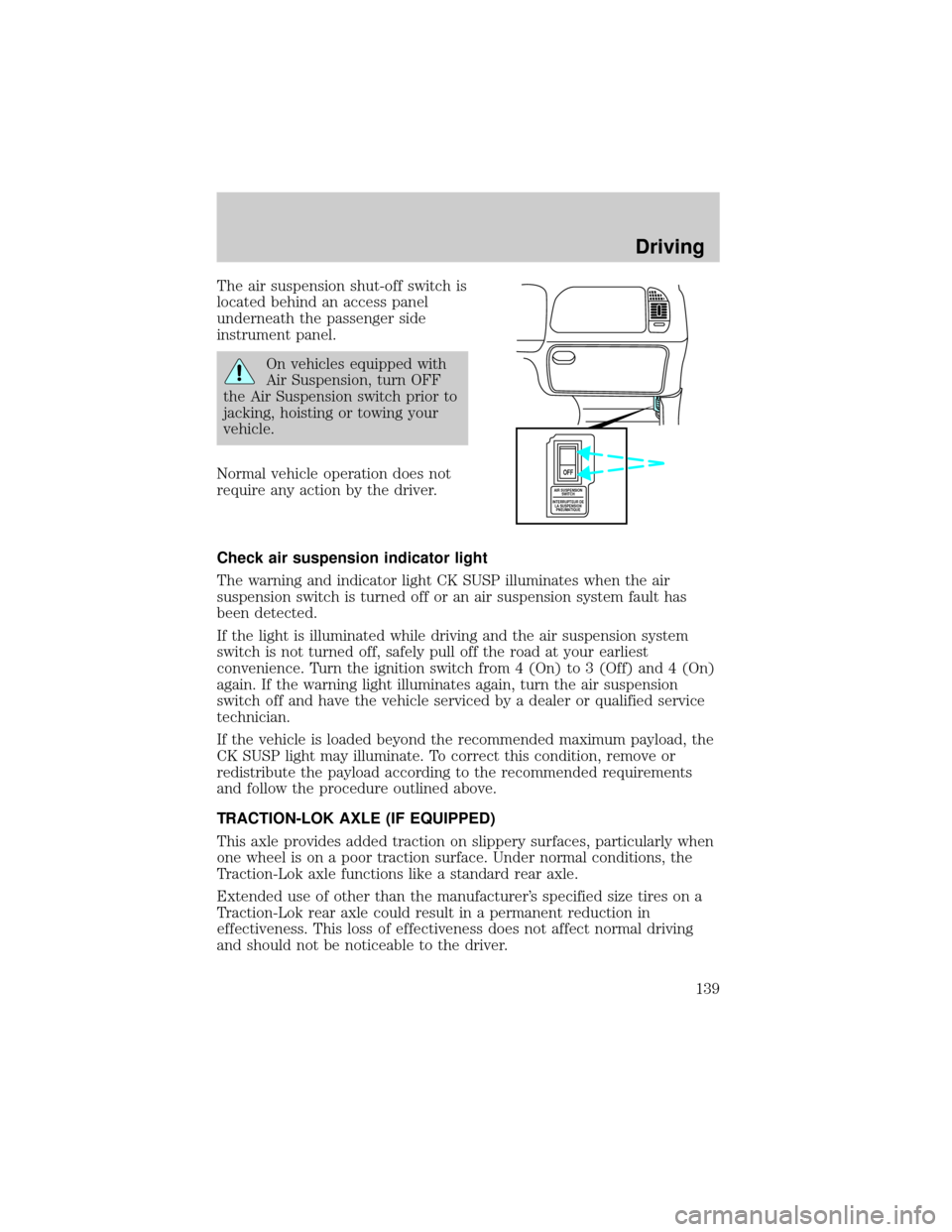
The air suspension shut-off switch is
located behind an access panel
underneath the passenger side
instrument panel.
On vehicles equipped with
Air Suspension, turn OFF
the Air Suspension switch prior to
jacking, hoisting or towing your
vehicle.
Normal vehicle operation does not
require any action by the driver.
Check air suspension indicator light
The warning and indicator light CK SUSP illuminates when the air
suspension switch is turned off or an air suspension system fault has
been detected.
If the light is illuminated while driving and the air suspension system
switch is not turned off, safely pull off the road at your earliest
convenience. Turn the ignition switch from 4 (On) to 3 (Off) and 4 (On)
again. If the warning light illuminates again, turn the air suspension
switch off and have the vehicle serviced by a dealer or qualified service
technician.
If the vehicle is loaded beyond the recommended maximum payload, the
CK SUSP light may illuminate. To correct this condition, remove or
redistribute the payload according to the recommended requirements
and follow the procedure outlined above.
TRACTION-LOK AXLE (IF EQUIPPED)
This axle provides added traction on slippery surfaces, particularly when
one wheel is on a poor traction surface. Under normal conditions, the
Traction-Lok axle functions like a standard rear axle.
Extended use of other than the manufacturer's specified size tires on a
Traction-Lok rear axle could result in a permanent reduction in
effectiveness. This loss of effectiveness does not affect normal driving
and should not be noticeable to the driver.
AIR SUSPENSION
SWITCH
INTERRUPTEUR DE
LA SUSPENSION
PNEUMATIQUE
OFF
Driving
139
Page 143 of 256
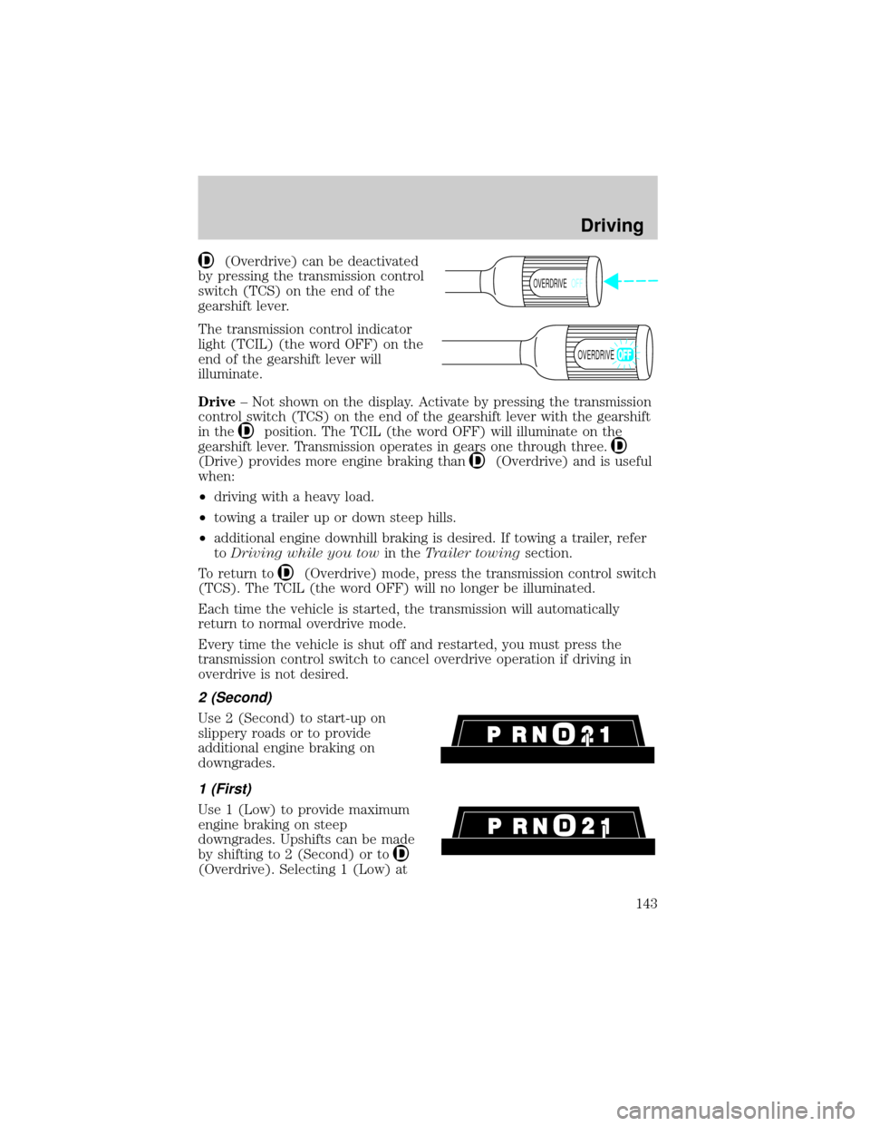
(Overdrive) can be deactivated
by pressing the transmission control
switch (TCS) on the end of the
gearshift lever.
The transmission control indicator
light (TCIL) (the word OFF) on the
end of the gearshift lever will
illuminate.
Drive± Not shown on the display. Activate by pressing the transmission
control switch (TCS) on the end of the gearshift lever with the gearshift
in the
position. The TCIL (the word OFF) will illuminate on the
gearshift lever. Transmission operates in gears one through three.
(Drive) provides more engine braking than(Overdrive) and is useful
when:
²driving with a heavy load.
²towing a trailer up or down steep hills.
²additional engine downhill braking is desired. If towing a trailer, refer
toDriving while you towin theTrailer towingsection.
To return to
(Overdrive) mode, press the transmission control switch
(TCS). The TCIL (the word OFF) will no longer be illuminated.
Each time the vehicle is started, the transmission will automatically
return to normal overdrive mode.
Every time the vehicle is shut off and restarted, you must press the
transmission control switch to cancel overdrive operation if driving in
overdrive is not desired.
2 (Second)
Use 2 (Second) to start-up on
slippery roads or to provide
additional engine braking on
downgrades.
1 (First)
Use 1 (Low) to provide maximum
engine braking on steep
downgrades. Upshifts can be made
by shifting to 2 (Second) or to
(Overdrive). Selecting 1 (Low) at
OVERDRIVEOFF
OVERDRIVE
Driving
143
Page 150 of 256
²Payload:Combined maximum allowable weight of cargo, passengers
and optional equipment. The payload equals the gross vehicle weight
rating minus base curb weight.
²GVW (Gross Vehicle Weight):Base curb weight plus payload
weight. The GVW is not a limit or a specification.
²GVWR (Gross Vehicle Weight Rating):Maximum total weight of
the base vehicle, passengers, optional equipment and cargo. The
GVWR is specific to each vehicle and is listed on the Safety
Compliance Label on the driver's door pillar.
²GAWR (Gross Axle Weight Rating):Carrying capacity for each axle
system. The GAWR is specific to each vehicle and is listed on the
Safety Compliance Label on the driver's door pillar.
²GCW (Gross Combined Weight):The combined weight of the
towing vehicle (including passengers and cargo) and the trailer.
²GCWR (Gross Combined Weight Rating):Maximum combined
weight of towing vehicle (including passengers and cargo) and the
trailer. The GCWR indicates the maximum loaded weight that the
vehicle is designed to tow.
²Maximum Trailer Weight Rating:Maximum weight of a trailer the
vehicle is permitted to tow. The maximum trailer weight rating is
determined by subtracting the vehicle curb weight for each
engine/transmission combination, any required option weight for trailer
towing and the weight of the driver from the GCWR for the towing
vehicle.
²Maximum Trailer Weight:Maximum weight of a trailer the loaded
vehicle (including passengers and cargo) is permitted to tow. It is
determined by subtracting the weight of the loaded trailer towing
vehicle from the GCWR for the towing vehicle.
²Trailer Weight Range:Specified weight range that the trailer must
fall within that ranges from zero to the maximum trailer weight rating.
Remember to figure in the tongue load of your loaded trailer when
figuring the total weight.
Do not exceed the GVWR or the GAWR specified on the
certification label.
Do not use replacement tires with lower load carrying capacities than the
originals because they may lower the vehicle's GVWR and GAWR
Driving
150
Page 151 of 256
limitations. Replacement tires with a higher limit than the originals do
not increase the GVWR and GAWR limitations.
The Certification Label, found on the inside pillar of the driver's door,
lists several important vehicle weight rating limitations. Before adding
any additional equipment, refer to these limitations. If you are adding
weight to the front of your vehicle, (potentially including weight added
to the cab), the weight added should not exceed the front axle reserve
capacity (FARC). Additional frontal weight may be added to the front
axle reserve capacity provided you limit your payload in other ways (i.e.
restrict the number of passengers or amount of cargo carried).
You may add equipment throughout your vehicle if the total weight
added is equal to or less than the total axle reserve capacity (TARC)
weight. You should NEVER exceed the total axle reserve capacity.
Always ensure that the weight of passengers, cargo and equipment being
carried is within the weight limitations that have been established for
your vehicle including both gross vehicle weight and Front and rear
gross axle weight rating limits. Under no circumstance should these
limitations be exceeded. Exceeding any vehicle weight rating limitation
could result in serious damage to the vehicle and/or personal injury.
Special loading instructions for owners of pickup trucks and
utility-type vehicles
For important information regarding safe operation of this type
of vehicle, see thePreparing to drive your vehiclesection in
theDrivingchapter of this owner guide.
Loaded vehicles, with a higher center of gravity, may handle
differently than unloaded vehicles. Extra precautions, such as
slower speeds and increased stopping distance, should be taken when
driving a heavily loaded vehicle.
Your vehicle has the capability to haul more cargo and people than most
passenger cars. Depending upon the type and placement of the load,
hauling cargo and people may raise the center of gravity of the vehicle.
Calculating the load your vehicle can carry/tow
1.
Use the appropriate maximum gross combined weight rating (GCWR)
chart to find the maximum GCWR for your type engine and rear axle ratio.
Driving
151