2000 DODGE NEON fuel pressure
[x] Cancel search: fuel pressurePage 726 of 1285

CAUTION: Do not drive cup plug into the casting
as restricted cooling can result and cause serious
engine problems.
INSTALLATION
Thoroughly clean all debris/rust from inside of cup
plug hole in cylinder block or head. Be sure to
remove old sealer. Lightly coat inside of cup plug hole
with MopartStud and Bearing Mount Adhesive.
Make certain the new plug is cleaned of all oil or
grease. Using a proper driver, drive plug into hole so
that the sharp edge of the plug is at least 0.5 mm
(0.020 inch.) inside the lead in chamfer (Fig. 3).
It is not necessary to wait for curing of the sealant.
The cooling system can be refilled and the vehicle
placed in service immediately.
ENGINE PERFORMANCE
If a loss of performance is noticed, timing belt or
chain may have skipped one or two teeth. Camshaft
and crankshaft timing should be checked. Refer to
Group 9, Engine Timing belt or chain installation.
It is important that the vehicle is operating to it's
optimum performance level to maintain fuel economy
and lowest vehicle emissions. If vehicle is not operat-ing to these standards, refer to Engine Diagnosis in
this section. The following procedures can assist in
achieving the proper engine diagnosis.
(1) Test cranking amperage draw. Refer to Group
8B, Starting.
(2) Check intake manifold for vacuum leaks.
(3) Perform cylinder compression pressure test.
Refer to Engine Diagnosis in this section.
(4) Clean or replace spark plugs as necessary and
adjust gap as specified in Group 8D, Ignition System.
Tighten to specifications.
(5) Test resistance of spark plug cables. Refer to
Group 8D, Ignition System.
(6) Test ignition coils primary and secondary resis-
tance. Replace parts as necessary. Refer to Group 8D,
Ignition System.
(7) Check fuel pump pressure at idle and different
RPM ranges. Refer to Group 14, Fuel System for
specifications.
(8) The air filter elements should be replaced as
specified in Group 0, Lubrication and Maintenance.
(9) Inspect crankcase ventilation system. Refer to
Group 25, Emission Control Systems.
(10) Road test vehicle as a final test.HONING CYLINDER BORES
(1) Used carefully, the cylinder bore resizing hone,
recommended tool C-823 or equivalent, equipped
with 220 grit stones, is the best tool for this honing
procedure. In addition to deglazing, it will reduce
taper and out-of-round as well as removing light
scuffing, scoring or scratches. Usually a few strokes
Fig. 2 Access Plug
1 ± CRANKSHAFT BOLT ACCESS PLUG
2 ± RIGHT MOUNT BOLT ACCESS PLUG
3 ± FASCIA
4 ± SPLASH SHIELD
Fig. 3 Core Hole Plug Removal
1 ± CYLINDER BLOCK
2 ± REMOVE PLUG WITH PLIERS
3 ± STRIKE HERE WITH HAMMER
4 ± DRIFT PUNCH
5 ± CUP PLUG
PLENGINE 9 - 3
GENERAL INFORMATION (Continued)
Page 729 of 1285
any fluid that may possibly be in the cylinder under
pressure.
(4) With all spark plugs removed, rotate engine
crankshaft using a breaker bar and socket.
(5) Identify the fluid in the cylinder(s) (i.e., cool-
ant, fuel, oil or other).
(6) Make sure all fluid has been removed from the
cylinders. Inspect engine for damage (i.e., connecting
rods, pistons, valves, etc.).
(7) Repair engine or components as necessary to
prevent this problem from re-occurring.
CAUTION: Squirt approximately one teaspoon of oil
into the cylinders, rotate engine to lubricate the cyl-
inder walls to prevent damage on restart.
(8) Install new spark plugs.
(9) Drain engine oil and remove oil filter.
(10) Fill engine with specified amount of approved
oil and install new oil filter.
(11) Connect negative battery cable.
(12) Start engine and check for any leaks.
CHECKING ENGINE OIL LEVEL
The best time to check engine oil level is after it
has sat overnight, or if the engine has been running,allow the engine to be shut off for at least 5 minutes
before checking oil level.
Checking the oil while the vehicle is on level
ground will improve the accuracy of the oil level
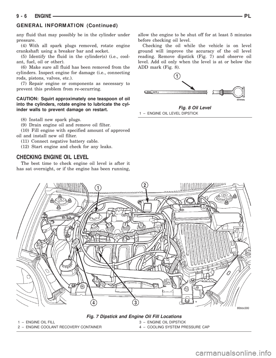
reading. Remove dipstick (Fig. 7) and observe oil
level. Add oil only when the level is at or below the
ADD mark (Fig. 8).
Fig. 7 Dipstick and Engine Oil Fill Locations
1 ± ENGINE OIL FILL
2 ± ENGINE COOLANT RECOVERY CONTAINER3 ± ENGINE OIL DIPSTICK
4 ± COOLING SYSTEM PRESSURE CAP
Fig. 8 Oil Level
1 ± ENGINE OIL LEVEL DIPSTICK
9 - 6 ENGINEPL
GENERAL INFORMATION (Continued)
Page 731 of 1285
ENGINE DIAGNOSIS
TABLE OF CONTENTS
page page
DIAGNOSIS AND TESTING
GENERAL INFORMATION...................8
INTAKE MANIFOLD LEAKAGE DIAGNOSIS......8
CYLINDER COMPRESSION PRESSURE TEST . . . 8
CYLINDER COMBUSTION PRESSURE
LEAKAGE TEST.........................9LASH ADJUSTER (TAPPET) NOISE
DIAGNOSIS............................9
ENGINE OIL LEAK INSPECTION..............9
ENGINE DIAGNOSISÐPERFORMANCE........11
ENGINE DIAGNOSISÐMECHANICAL.........12
DIAGNOSIS AND TESTING
GENERAL INFORMATION
Engine diagnosis is helpful in determining the
causes of malfunctions not detected and remedied by
routine maintenance.
These malfunctions may be classified as either
mechanical (e.g., a strange noise), or performance
(e.g., engine idles rough and stalls).
Refer to the Service DiagnosisÐMechanical Chart
and the Service DiagnosisÐPerformance Chart, for
possible causes and corrections of malfunctions. Refer
to Group 14, Fuel System, for the fuel system diag-
nosis.
Additional tests and diagnostic procedures may be
necessary for specific engine malfunctions that can-
not be isolated with the Service Diagnosis charts.
Information concerning additional tests and diagno-
sis is provided within the following:
²Cylinder Compression Pressure Test
²Cylinder Combustion Pressure Leakage Test
²Engine Cylinder Head Gasket Failure Diagnosis
²Intake Manifold Leakage Diagnosis
INTAKE MANIFOLD LEAKAGE DIAGNOSIS
An intake manifold air leak is characterized by
lower than normal manifold vacuum. Also, one or
more cylinders may not be functioning.
WARNING: USE EXTREME CAUTION WHEN THE
ENGINE IS OPERATING. DO NOT STAND IN A
DIRECT LINE WITH THE FAN. DO NOT PUT YOUR
HANDS NEAR THE PULLEYS, BELTS OR THE FAN.
DO NOT WEAR LOOSE CLOTHING.
(1) Start the engine.
(2) Spray a small stream of water (Spray Bottle) at
the suspected leak area.
(3) If engine RPM'S change, the area of the sus-
pected leak has been found.
(4) Repair as required.
CYLINDER COMPRESSION PRESSURE TEST
The results of a cylinder compression pressure test
can be utilized to diagnose several engine malfunc-
tions.
Ensure the battery is completely charged and the
engine starter motor is in good operating condition.
Otherwise the indicated compression pressures may
not be valid for diagnosis purposes.
(1) Check engine oil level and add oil if necessary.
(2) Drive the vehicle until engine reaches normal
operating temperature. Select a route free from traf-
fic and other forms of congestion, observe all traffic
laws, and accelerate through the gears several times
briskly.
(3) Remove all spark plugs from engine. As spark
plugs are being removed, check electrodes for abnor-
mal firing indicators fouled, hot, oily, etc. Record cyl-
inder number of spark plug for future reference.
(4) Disconnect coil wire from distributor and
secure to good ground to prevent a spark from start-
ing a fire (Conventional Ignition System). For Direct
Ignition System DIS disconnect the coil connector.
(5) Be sure throttle blade is fully open during the
compression check.
(6) Insert compression gage adaptor into the #1
spark plug hole in cylinder head. Crank engine until
maximum pressure is reached on gage. Record this
pressure as #1 cylinder pressure.
(7) Repeat the previous step for all remaining cyl-
inders.
(8) Compression should not be less than (689 kPa)
100 psi and not vary more than 25 percent from cyl-
inder to cylinder.
(9) If one or more cylinders have abnormally low
compression pressures, repeat the compression test.
(10) If the same cylinder or cylinders repeat an
abnormally low reading on the second compression
test, it could indicate the existence of a problem in
the cylinder in question.The recommended com-
pression pressures are to be used only as a
guide to diagnosing engine problems. An engine
9 - 8 ENGINEPL
Page 732 of 1285

should not be disassembled to determine the
cause of low compression unless some malfunc-
tion is present.
(11) Clean or replace spark plugs as necessary and
adjust gap as specified in Group 8, Electrical.
Tighten to specifications.
(12) Test resistance of spark plug cables. Refer to
Group 8, Electrical Ignition System Secondary Cir-
cuit Inspection.
(13) Test coil output voltage, primary and second-
ary resistance. Replace parts as necessary. Refer to
Group 8, Electrical Ignition System.
(14) Check fuel pump pressure at idle and differ-
ent RPM ranges. Refer to Group 14, Fuel System for
Specifications.
(15) The air filter elements should be replaced as
specified in Group 0, Lubrication and Maintenance.
(16) Inspect crankcase ventilation system as out
lined in Group 0, Lubrication and Maintenance. For
emission controls see Group 25, Emission Controls
for service procedures.
(17) Inspect and adjust accessory belt drives refer-
ring to Group 7, Cooling System, Accessory Drive
Belts for proper adjustments.
(18) Road test vehicle as a final test.
CYLINDER COMBUSTION PRESSURE LEAKAGE
TEST
The combustion pressure leakage test provides an
accurate means for determining engine condition.
Combustion pressure leakage testing will detect:
²Exhaust and intake valve leaks (improper seat-
ing).
²Leaks between adjacent cylinders or into water
jacket.
²Any causes for combustion/compression pressure
loss.
WARNING: DO NOT REMOVE THE RADIATOR CAP
WITH THE SYSTEM HOT AND UNDER PRESSURE
BECAUSE SERIOUS BURNS FROM COOLANT CAN
OCCUR.
Check the coolant level and fill as required. DO
NOT install the radiator cap.
Start and operate the engine until it attains nor-
mal operating temperature, then turn the engine
OFF.
Clean spark plug recesses with compressed air.
Remove the spark plugs.
Remove the oil filler cap.
Remove the air cleaner.
Calibrate the tester according to the manufactur-
er's instructions. The shop air source for testing
should maintain 483 kPa (70 psi) minimum, 1,379kPa (200 psi) maximum, with 552 kPa (80 psi) rec-
ommended.
Perform the test procedures on each cylinder
according to the tester manufacturer's instructions.
While testing, listen for pressurized air escaping
through the throttle body, tailpipe and oil filler cap
opening. Check for bubbles in the radiator coolant.
All gauge pressure indications should be equal,
with no more than 25% leakage per cylinder.
FOR EXAMPLE:At 552 kPa (80 psi) input pres-
sure, a minimum of 414 kPa (60 psi) should be main-
tained in the cylinder.
LASH ADJUSTER (TAPPET) NOISE DIAGNOSIS
A tappet-like noise may be produced from several
items. Check the following items.
(1) Engine oil level too high or too low. This may
cause aerated oil to enter the adjusters and cause
them to be spongy.
(2) Insufficient running time after rebuilding cylin-
der head. Low speed running up to 1 hour may be
required.
(3) During this time, turn engine off and let set for
a few minutes before restarting. Repeat this several
times after engine has reached normal operating
temperature.
(4) Low oil pressure.
(5) The oil restrictor pressed into the vertical oil
passage to the cylinder head is plugged with debris.
(6) Air ingested into oil due to broken or cracked
oil pump pick up.
(7) Worn valve guides.
(8) Rocker arm ears contacting valve spring
retainer.
(9) Rocker arm loose, adjuster stuck or at maxi-
mum extension and still leaves lash in the system.
(10) Faulty lash adjuster.
a. Check lash adjusters for sponginess while
installed in cylinder head. Depress part of rocker
arm over adjuster. Normal adjusters should feel very
firm. Spongy adjusters can be bottomed out easily.
b. Remove suspected rocker arms (sohc) or lash
adjuster (dohc) and replace.
ENGINE OIL LEAK INSPECTION
Begin with a thorough visual inspection of the
engine, particularly at the area of the suspected leak.
If an oil leak source is not readily identifiable, the
following steps should be followed:
(1) Do not clean or degrease the engine at this
time because some solvents may cause rubber to
swell, temporarily stopping the leak.
(2) Add an oil soluble dye (use as recommended by
manufacturer). Start the engine and let idle for
approximately 15 minutes. Check the oil dipstick to
PLENGINE 9 - 9
DIAGNOSIS AND TESTING (Continued)
Page 735 of 1285
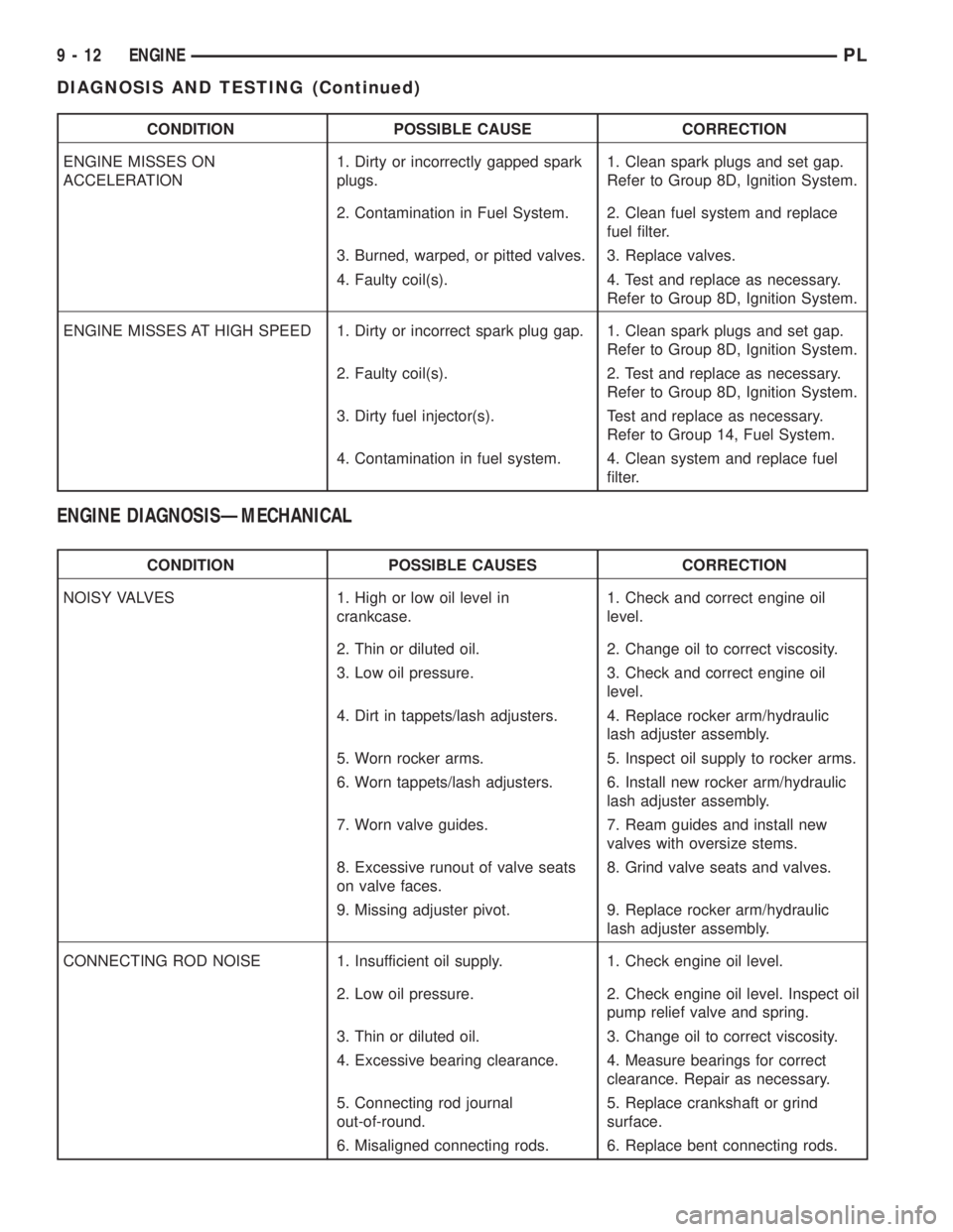
CONDITION POSSIBLE CAUSE CORRECTION
ENGINE MISSES ON
ACCELERATION1. Dirty or incorrectly gapped spark
plugs.1. Clean spark plugs and set gap.
Refer to Group 8D, Ignition System.
2. Contamination in Fuel System. 2. Clean fuel system and replace
fuel filter.
3. Burned, warped, or pitted valves. 3. Replace valves.
4. Faulty coil(s). 4. Test and replace as necessary.
Refer to Group 8D, Ignition System.
ENGINE MISSES AT HIGH SPEED 1. Dirty or incorrect spark plug gap. 1. Clean spark plugs and set gap.
Refer to Group 8D, Ignition System.
2. Faulty coil(s). 2. Test and replace as necessary.
Refer to Group 8D, Ignition System.
3. Dirty fuel injector(s). Test and replace as necessary.
Refer to Group 14, Fuel System.
4. Contamination in fuel system. 4. Clean system and replace fuel
filter.
ENGINE DIAGNOSISÐMECHANICAL
CONDITION POSSIBLE CAUSES CORRECTION
NOISY VALVES 1. High or low oil level in
crankcase.1. Check and correct engine oil
level.
2. Thin or diluted oil. 2. Change oil to correct viscosity.
3. Low oil pressure. 3. Check and correct engine oil
level.
4. Dirt in tappets/lash adjusters. 4. Replace rocker arm/hydraulic
lash adjuster assembly.
5. Worn rocker arms. 5. Inspect oil supply to rocker arms.
6. Worn tappets/lash adjusters. 6. Install new rocker arm/hydraulic
lash adjuster assembly.
7. Worn valve guides. 7. Ream guides and install new
valves with oversize stems.
8. Excessive runout of valve seats
on valve faces.8. Grind valve seats and valves.
9. Missing adjuster pivot. 9. Replace rocker arm/hydraulic
lash adjuster assembly.
CONNECTING ROD NOISE 1. Insufficient oil supply. 1. Check engine oil level.
2. Low oil pressure. 2. Check engine oil level. Inspect oil
pump relief valve and spring.
3. Thin or diluted oil. 3. Change oil to correct viscosity.
4. Excessive bearing clearance. 4. Measure bearings for correct
clearance. Repair as necessary.
5. Connecting rod journal
out-of-round.5. Replace crankshaft or grind
surface.
6. Misaligned connecting rods. 6. Replace bent connecting rods.
9 - 12 ENGINEPL
DIAGNOSIS AND TESTING (Continued)
Page 748 of 1285
STRUCTURAL COLLAR
REMOVAL
(1) Raise vehicle on hoist.NOTE: To remove transaxle dust cover, the front
bending strut must be removed.
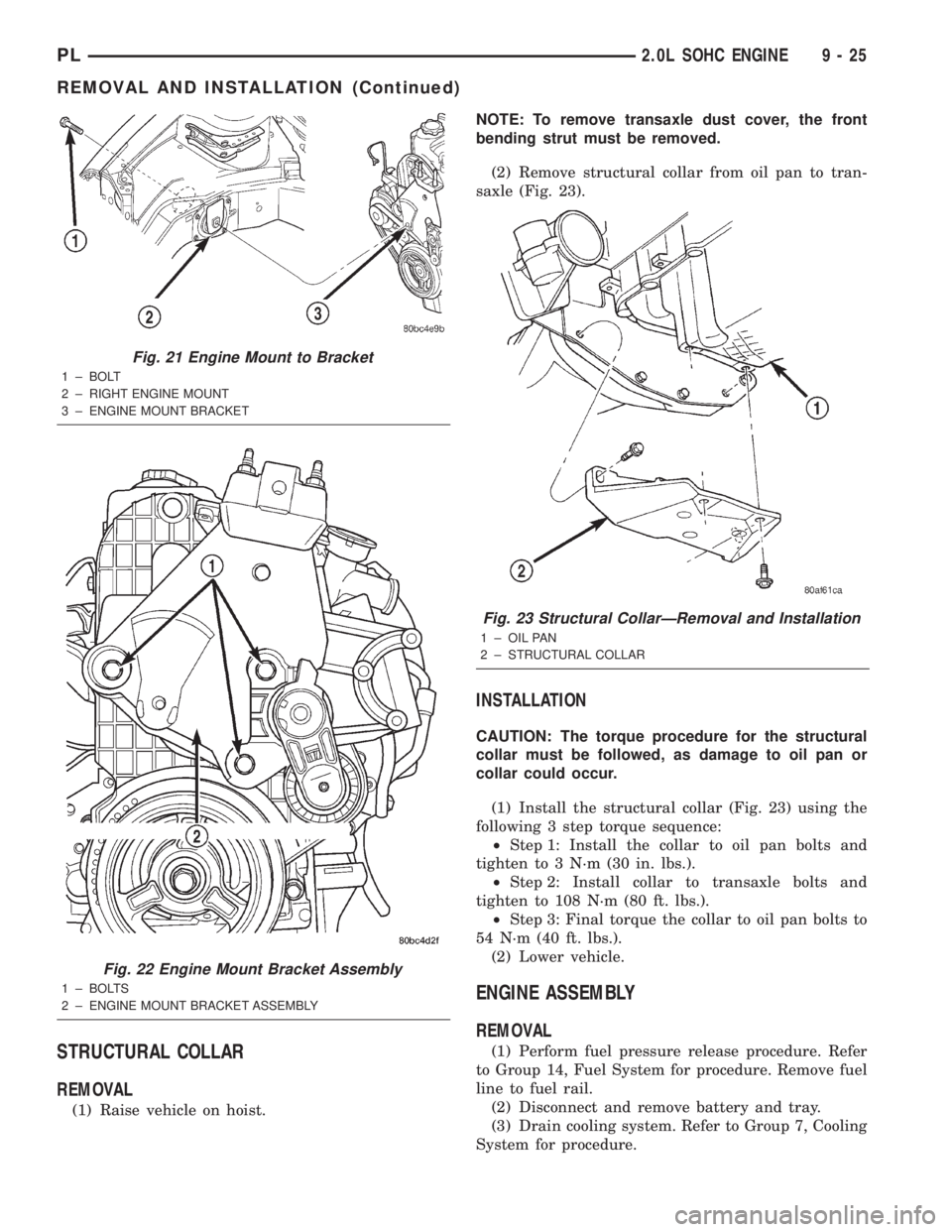
(2) Remove structural collar from oil pan to tran-
saxle (Fig. 23).
INSTALLATION
CAUTION: The torque procedure for the structural
collar must be followed, as damage to oil pan or
collar could occur.
(1) Install the structural collar (Fig. 23) using the
following 3 step torque sequence:
²Step 1: Install the collar to oil pan bolts and
tighten to 3 N´m (30 in. lbs.).
²Step 2: Install collar to transaxle bolts and
tighten to 108 N´m (80 ft. lbs.).
²Step 3: Final torque the collar to oil pan bolts to
54 N´m (40 ft. lbs.).
(2) Lower vehicle.
ENGINE ASSEMBLY
REMOVAL
(1) Perform fuel pressure release procedure. Refer
to Group 14, Fuel System for procedure. Remove fuel
line to fuel rail.
(2) Disconnect and remove battery and tray.
(3) Drain cooling system. Refer to Group 7, Cooling
System for procedure.
Fig. 21 Engine Mount to Bracket
1 ± BOLT
2 ± RIGHT ENGINE MOUNT
3 ± ENGINE MOUNT BRACKET
Fig. 22 Engine Mount Bracket Assembly
1 ± BOLTS
2 ± ENGINE MOUNT BRACKET ASSEMBLY
Fig. 23 Structural CollarÐRemoval and Installation
1 ± OIL PAN
2 ± STRUCTURAL COLLAR
PL2.0L SOHC ENGINE 9 - 25
REMOVAL AND INSTALLATION (Continued)
Page 751 of 1285
(27) Start engine and run until operating temper-
ature is reached.
(28) Ensure engine is properly positioned. Refer to
Torque Struts in this section for adjustment proce-
dure.
(29) Adjust transmission linkage, if necessary.
INTAKE MANIFOLD
REMOVAL
WARNING: RELEASE FUEL SYSTEM PRESSURE
BEFORE SERVICING FUEL SYSTEM COMPONENTS.
SERVICE VEHICLES IN WELL VENTILATED AREAS
AND AVOID IGNITION SOURCES. NEVER SMOKE
WHILE SERVICING THE VEHICLE.
(1) Disconnect negative cable from battery.
(2) Remove the inlet air duct from intake manifold
to throttle body.
(3) Perform fuel system pressure release procedure
before attempting any repairs.Refer to Group 14,
Fuel System for procedures.
WARNING: WRAP SHOP TOWELS AROUND FUEL
HOSE TO CATCH ANY GASOLINE SPILLAGE
(4) Disconnect fuel supply line quick connect at the
fuel tube assembly. Refer to Group 14, Fuel System
for procedures.
(5) Remove fuel rail assembly attaching screws
and remove fuel rail assembly from engine. Cover
injector holes with suitable covering.
CAUTION: Do not set fuel injectors on their tips,
damage may occur to the injectors
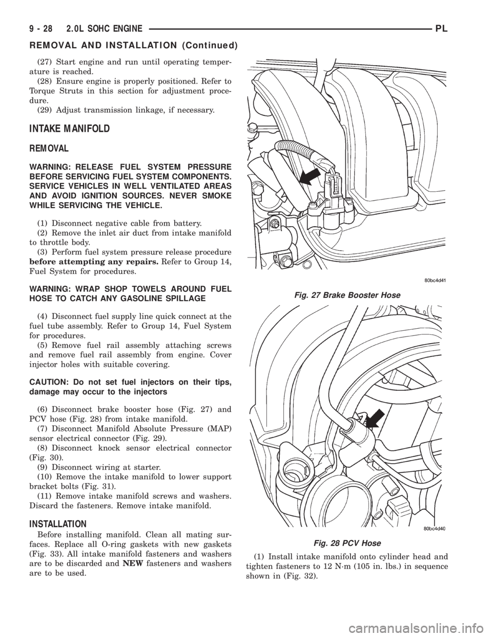
(6) Disconnect brake booster hose (Fig. 27) and
PCV hose (Fig. 28) from intake manifold.
(7) Disconnect Manifold Absolute Pressure (MAP)
sensor electrical connector (Fig. 29).
(8) Disconnect knock sensor electrical connector
(Fig. 30).
(9) Disconnect wiring at starter.
(10) Remove the intake manifold to lower support
bracket bolts (Fig. 31).
(11) Remove intake manifold screws and washers.
Discard the fasteners. Remove intake manifold.
INSTALLATION
Before installing manifold. Clean all mating sur-
faces. Replace all O-ring gaskets with new gaskets
(Fig. 33). All intake manifold fasteners and washers
are to be discarded andNEWfasteners and washers
are to be used.(1) Install intake manifold onto cylinder head and
tighten fasteners to 12 N´m (105 in. lbs.) in sequence
shown in (Fig. 32).
Fig. 27 Brake Booster Hose
Fig. 28 PCV Hose
9 - 28 2.0L SOHC ENGINEPL
REMOVAL AND INSTALLATION (Continued)
Page 752 of 1285
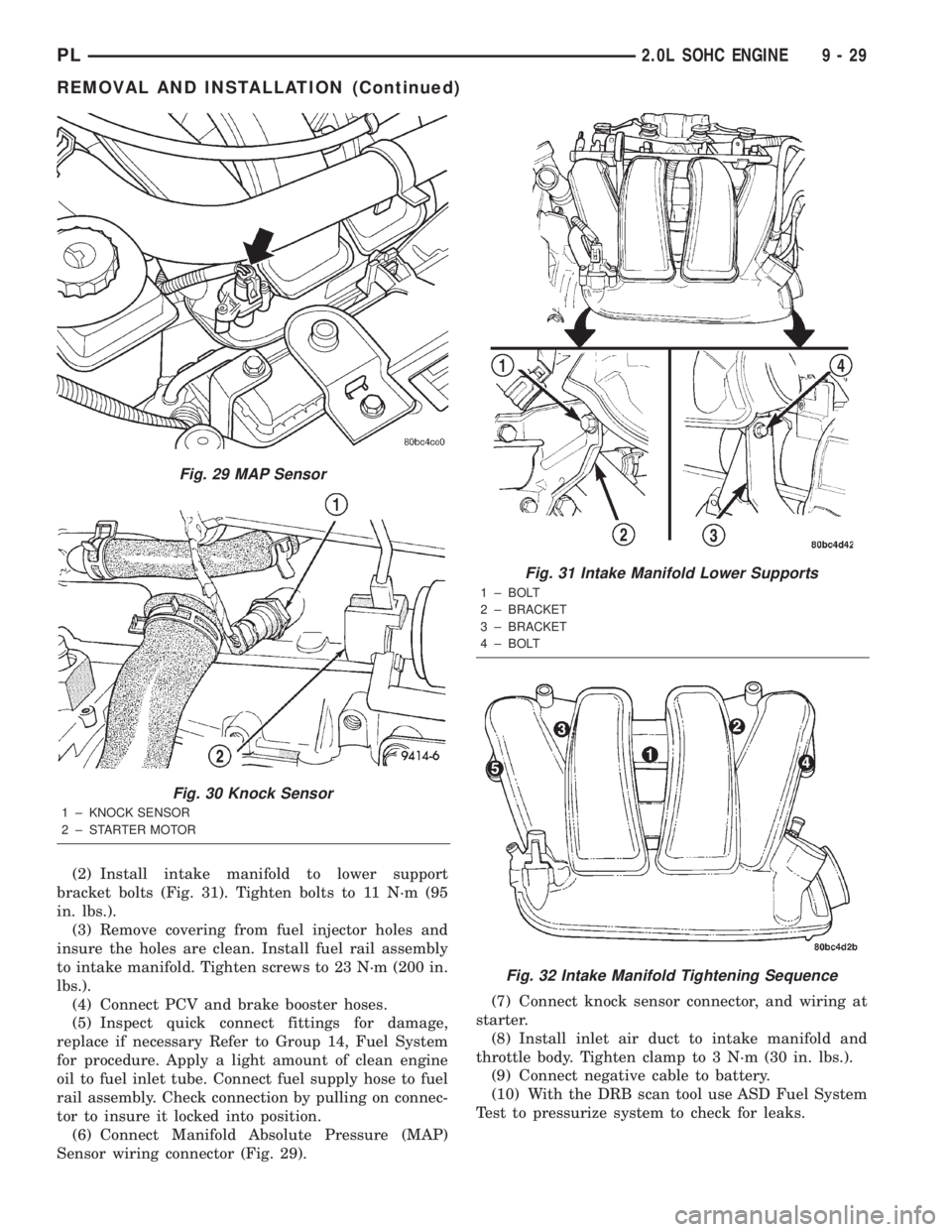
(2) Install intake manifold to lower support
bracket bolts (Fig. 31). Tighten bolts to 11 N´m (95
in. lbs.).
(3) Remove covering from fuel injector holes and
insure the holes are clean. Install fuel rail assembly
to intake manifold. Tighten screws to 23 N´m (200 in.
lbs.).
(4) Connect PCV and brake booster hoses.
(5) Inspect quick connect fittings for damage,
replace if necessary Refer to Group 14, Fuel System
for procedure. Apply a light amount of clean engine
oil to fuel inlet tube. Connect fuel supply hose to fuel
rail assembly. Check connection by pulling on connec-
tor to insure it locked into position.
(6) Connect Manifold Absolute Pressure (MAP)
Sensor wiring connector (Fig. 29).(7) Connect knock sensor connector, and wiring at
starter.
(8) Install inlet air duct to intake manifold and
throttle body. Tighten clamp to 3 N´m (30 in. lbs.).
(9) Connect negative cable to battery.
(10) With the DRB scan tool use ASD Fuel System
Test to pressurize system to check for leaks.
Fig. 29 MAP Sensor
Fig. 30 Knock Sensor
1 ± KNOCK SENSOR
2 ± STARTER MOTOR
Fig. 31 Intake Manifold Lower Supports
1 ± BOLT
2 ± BRACKET
3 ± BRACKET
4 ± BOLT
Fig. 32 Intake Manifold Tightening Sequence
PL2.0L SOHC ENGINE 9 - 29
REMOVAL AND INSTALLATION (Continued)