Page 9 of 92
11
7
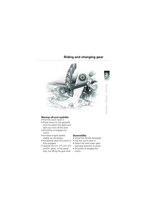
General information and controls
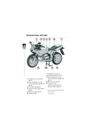
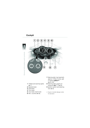
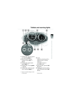
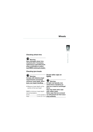
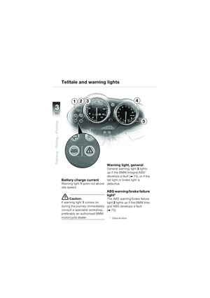
1Telltale light, left turn indica-
tor repeater green
s
2 Warning light, battery
charge current red
r
(
b 62)
3 Telltale light, high (main)
beam blue
q
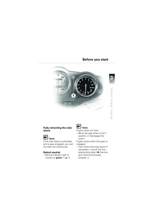
4Telltale light, neutral green
k (b 59)
5 Telltale light, right turn indi-
cator repeater green
t
( ) Figures in brackets bpage number
for description
6 Clock
Adjust by pressing with a
ballpoint pen or similar
object at
point A(minutes) or
point B (hours)
7 Warning light, general red
e (b 62)
8 Telltale and warning lights,
ABS
l/brake failure red *
(
b 62)
* Optional extra
Telltale and warning lights
7
12354
8
B6A
10sbkg4.bk Seite 7 Dienstag, 29. Juni 2010 9:21 09
Page 10 of 92
11
8
General information and controls
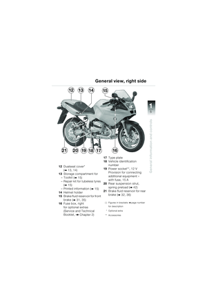
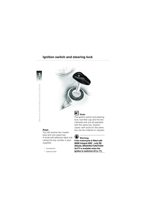
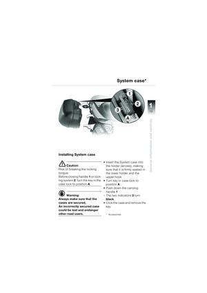
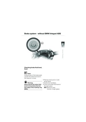
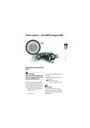
KeysYou will receive two master
keys and one spare key.
A small self-adhesive label indi-
cating the key number is also
supplied.
* Accessories
** Optional extra
L Note:
The ignition switch and steering
lock, fuel filler cap and the hel-
met/seat lock are all operated
with the same key. System
cases
* with locks for the same
key can be ordered on request.
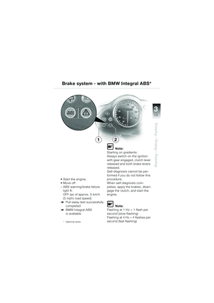
d Warning:
If the motorcycle is fitted with
BMW Integral ABS
**, only RE-
SIDUAL BRAKING FUNCTION-
ALITY is available when the
ignition is switched off (b 71 )
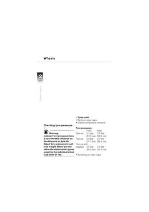
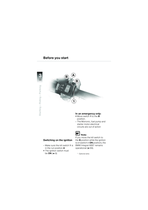
Ignition switch and steering lock
10sbkg4.bk Seite 8 Dienstag, 29. Juni 2010 9:21 09
Page 11 of 92
11
9
General information and controls
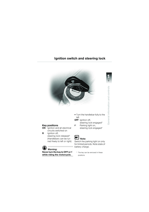
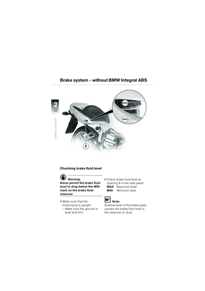
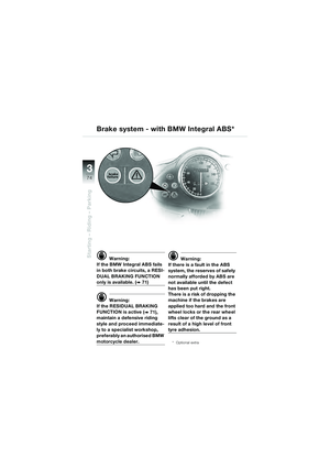
Ignition switch and steering lock
Key positionsONIgnition and all electrical
circuits switched on
R Ignition off,
steering lock released*
(Handlebars can be tur-
ned freely to left or right)
d Warning:
Never turn the key to OFF or
I
while riding the motorcycle. Turn the handlebar fully to the
left
OFF Ignition off,
steering lock engaged*
IParking light on,
steering lock engaged*
L Note:
Switch the parking light on only
for limited periods. Note state of
battery charge.
* The key can be removed in these
positions
10sbkg4.bk Seite 9 Dienstag, 29. Juni 2010 9:21 09
Page 12 of 92
11
10
General information and controls
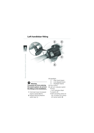
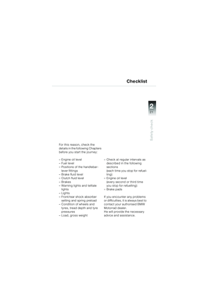
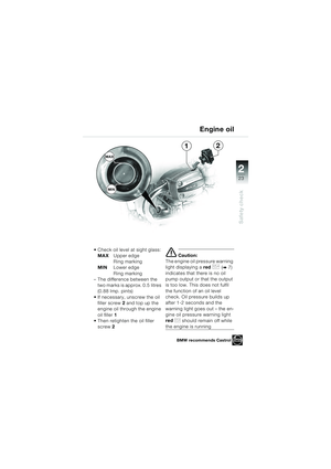
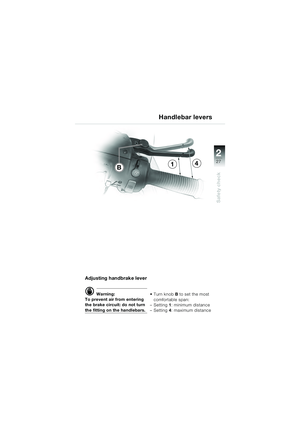
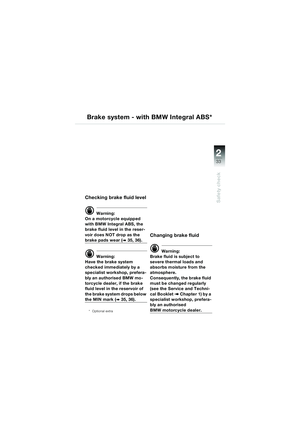
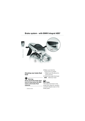
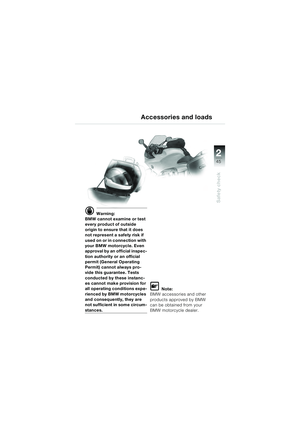
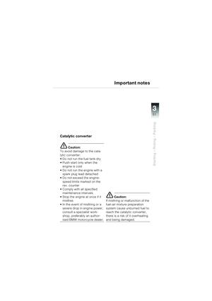
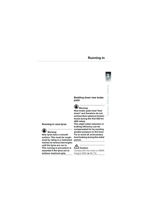
d Warning:
To prevent air from entering
the clutch system: do not turn
the fitting on the handlebars.
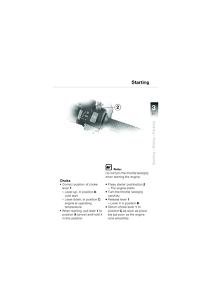
1 Cold start lever (increased
engine speed) (
b 61)
2 Hazard warning flashers
switch (
b 12) 3
Headlight
FHigh (main) beam
GLow (dipped) beam
FHeadlight flasher
4 Horn button
5 Left turn indicator switch
–Turn indicators flash
To switch off:
Self-cancelling while rid-
ing, or press turn-indica-
tor cancel switch 9
Left handlebar fitting
23
4
5
1
10sbkg4.bk Seite 10 Dienstag, 29. Juni 2010 9:21 09
Page 13 of 92
11
11
General information and controls
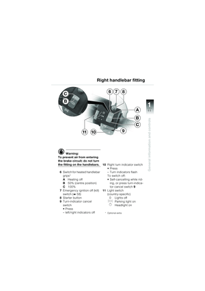
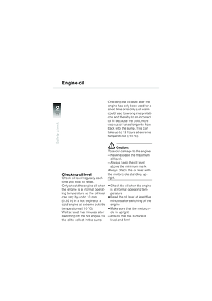
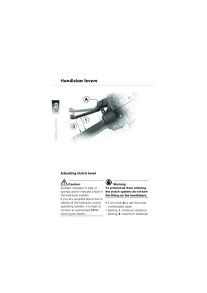
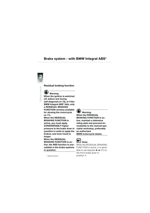
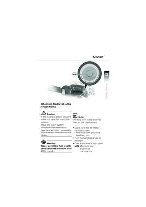
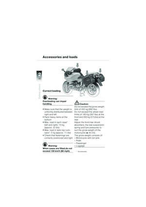
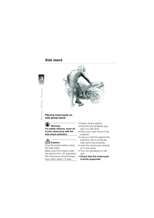
d Warning:
To prevent air from entering
the brake circuit: do not turn
the fitting on the handlebars.
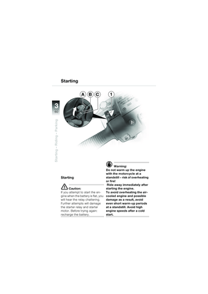
6 Switch for heated handlebar
grips*
A Heating off
B 50% (centre position)
C 100%
7 Emergency ignition off (kill)
switch (
b 58)
8 Starter button
9 Turn-indicator cancel
switch
– left/right indicators off 10
Right turn indicator switch
– Turn indicators flash
To switch off:
Self-cancelling while rid-
ing, or press turn-indica-
tor cancel switch 9
11 Light switch
(country-specific)
0 Lights off
JParking light on
KHeadlight on
* Optional extra
Right handlebar fitting
7
B
C
A
68
91011
C
B
10sbkg4.bk Seite 11 Dienstag, 29. Juni 2010 9:21 09
Page 14 of 92
11
12
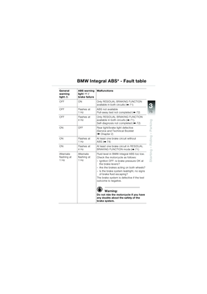
General information and controls
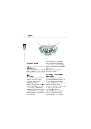
1
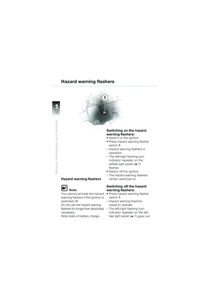
Hazard warning flashers
L Note:
You cannot activate the hazard
warning flashers if the ignition is
switched off.
Do not use the hazard warning
flashers for longer than absolutely
necessary.
Note state of battery charge.
Switching on the hazard
warning flashers:
Switch on the ignition
Press hazard warning flasher switch 1
– Hazard warning flashers in operation
– The left/right flashing turn indicator repeater on the
telltale light panel (
b 7)
flashes
Switch off the ignition
– The hazard warning flashers remain switched on
Switching off the hazard
warning flashers:
Press hazard warning flasher switch 1
– Hazard warning flashers cease to operate
– The left/right flashing turn indicator repeater on the tell-
tale light panel (
b 7) goes out
Hazard warning flashers
10sbkg4.bk Seite 12 Dienstag, 29. Juni 2010 9:21 09
Page 15 of 92
11
13
General information and controls
2
3
14
1
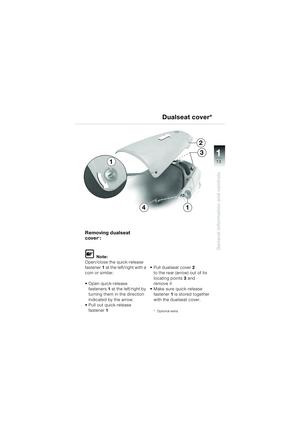
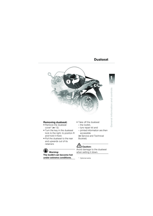
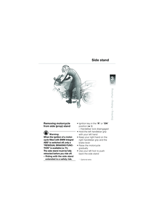
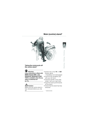
Removing dualseat
cover
*:
L Note:
Open/close the quick-release
fastener 1 at the left/right with a
coin or similar.
Open quick-release fasteners 1 at the left/right by
turning them in the direction
indicated by the arrow.
Pull out quick-release
fastener 1
2
to the rear (arrow) out of its
locating points 3 and
remove it
Make sure quick-release fastener 1 is stored together
with the dualseat cover.
* Optional extra
Dualseat cover*
10sbkg4.bk Seite 13 Dienstag, 29. Juni 2010 9:21 09
Page 16 of 92
11
14
General information and controls
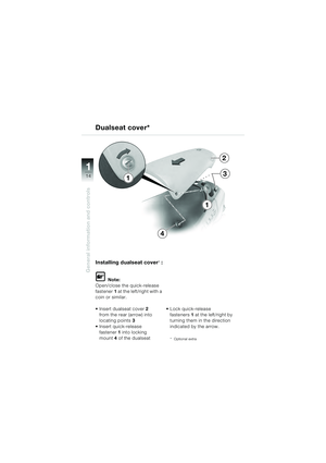
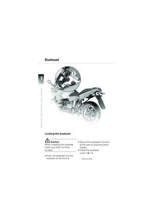
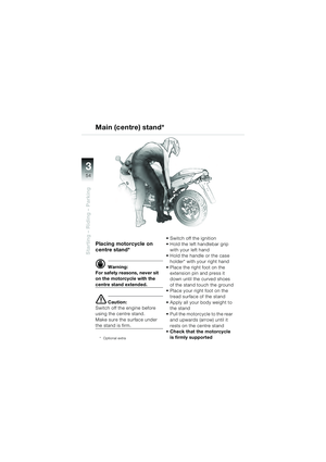
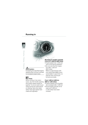
Installing dualseat cover*:
L Note:
Open/close the quick-release
fastener 1 at the left/right with a
coin or similar.
Insert dualseat cover 2
from the rear (arrow) into
locating points 3
Insert quick-release fastener 1 into locking
mount 4 of the dualseat Lock quick-release
fasteners 1 at the left/right by
turning them in the direction
indicated by the arrow.
* Optional extra
Dualseat cover*
2
3
4
1
1
10sbkg4.bk Seite 14 Dienstag, 29. Juni 2010 9:21 09


 11
7
General information and controls
1Telltale light, left turn indica-
tor repeater green
s
2 Warning light, battery
charge current red
r
(
b 62)
3 Telltale light, high (main)
beam blue
q
4")
 11
8
General information and controls
KeysYou will receive two master
keys and one spare key.
A small self-adhesive label indi-
cating the key number is also
supplied.
* Accessories
** Optional extr")
 11
9
General information and controls
Ignition switch and steering lock
Key positionsONIgnition and all electrical
circuits switched on
R Ignition off,
steering lock released*
(Handlebars can be tur-")
 11
10
General information and controls
d Warning:
To prevent air from entering
the clutch system: do not turn
the fitting on the handlebars.
1 Cold start lever (increased
engine speed) (
b 61)
2 Ha")
 11
11
General information and controls
d Warning:
To prevent air from entering
the brake circuit: do not turn
the fitting on the handlebars.
6 Switch for heated handlebar
grips*
A Heating off
B 50%")
 11
12
General information and controls
1
Hazard warning flashers
L Note:
You cannot activate the hazard
warning flashers if the ignition is
switched off.
Do not use the hazard warning
flashers for")
 11
13
General information and controls
2
3
14
1
Removing dualseat
cover
*:
L Note:
Open/close the quick-release
fastener 1 at the left/right with a
coin or similar.
Open quick-release fasteners 1")
 11
14
General information and controls
Installing dualseat cover*:
L Note:
Open/close the quick-release
fastener 1 at the left/right with a
coin or similar.
Insert dualseat cover 2
from the rear (")