2000 AUDI ALLROAD heating
[x] Cancel search: heatingPage 10 of 306

1
2
3
4 5
6
7
8
9
10
11 12
13 14
15
16
17 Power
window switches
Door handle
Power locking switch
Light switch
Air vents
Turn signals I headlight dimmer switch lever ...
Cruise control ................. .............
Instrument illumination
Horn, driver's airbag •••••
0 •• 0 •• 0 0 •• 0 ••• 0 ••• 0
Radio I CD I buttons ................
........
Radio I CD I telephone buttons ...............
Instrument cluster ....... ... ... ... ... .. .....
Warning I indi cator lights ••••••••
0 0
••••••••••
Windshield wiper I washer lever ..............
Tri p computer function control switch .........
Steering lock I ignition I starter switch
Switch for the Electronic Stability Program (i::SP)
Switches for the ride heigh t adjustment and
level display •••••••••••••••
0 •• 0 •• 0 0 •• 0 0 ••••
Emergenc y flasher
Cup holder
Glove compartment (lockable)
Front passenger's airbag
Radio Page
69
59 62
148 165
15 6
15 8
149
25
185
18 6
11 6
12 2
16 0
146
113
15 2
15 3
15 2
18 2
17 8
25 -------GE NERA L ILLUST
RATION
Page
18 Thumb wheel for seat heating
150
19 Switch for rear window defogger 151
20 Climate controls
162
21 Ashtray ...................................
180
Cigarette lighter ............................ 181
22 Gearshift lever or
Selector lever ..............................
104
23 Adjuster control for outside mirrors
72
24 Parking brake lever
103
25 Navigation System switch or
Cup holder
•••••••••••••••• 0 •••• 0 •••• 0 •••••
182
26 Storage compartment
27 Service wallet compartment
183
28 Adjustable steering wheel
98
29 Data Link Connector (DLC) for On Board
Diagnostics (OBD)
128
30 Release lever for engine hood 231
31 Memory for driver's seat
81
Notes
• Some features mentioned are standard equipment on some
models only and options on others.
• For technical reasons, the arrangement of the switches and indi
cator /warning lights may differ. The govern ing factor is the symbol
on the switch itself.
9
Page 151 of 306

CONTROLS AND
EQUIPMENT--------------------
1 and 4-Electrically heated ... 8
seats• utJ
The heating elements in both seats can be
turned on and regulated separately with the
two thumb wheel switches.
With the ignition on, the seat cushion and
backrest of the front seats can be heated
electrically.
15 0 1
- Use this thumb wheel switch to activate
and regulate the heating elements in the
driver's seat.
4- Use this thumbwheel switch to activate
and regulate the heating elements in the
front passenger's seat.
From position 0, roll thumbwheel upward to
activate the heating elements.
Select the desired temperature setting be
tween positions 1-6. When the heating ele
ments are activated, the numbers on the
thumb wheel will light up.
The steering wheel heating* is
swit ched on automatically when the seat
heating is switched on. The temperature.
however, remains at a constant preset level
and cannot be regulated with the thumb
wheel (1).
Note
To prevent possible damage to the heating
elements, do not kneel on the seats or in
any other way apply a heavy load to relative
ly small areas of the seat. The
heating elements* for the left and right
seating positions of the rear seat bench are
switched on and off and regulated by the
thumbwheel in the center console:
a - left
b- right
The rear seat heating* only operates when
a sensor registers the weight of the occu
pant on the seat.
Select the desired temperature setting be
tween positions 1-6. When the heating ele
ments are activated, the numb ers on the
thumbwheel will light up.
Page 156 of 306

---------------------CONTROLS AND EQUIPMEN T
Notes continued
• At excessive loads (for example, over
heating caused by frequent changes in the
ride height when the vehicle is stationary),
the system is temporarily deactivated for
safety reasons. The system will return to
full operation once it has cooled down.
• The system automatically switches to
the normal level if the ESP automatically
shuts off (see page 205). If this happens,
switch the ignition off, and then on again.
Now you can select the desired level once
again.
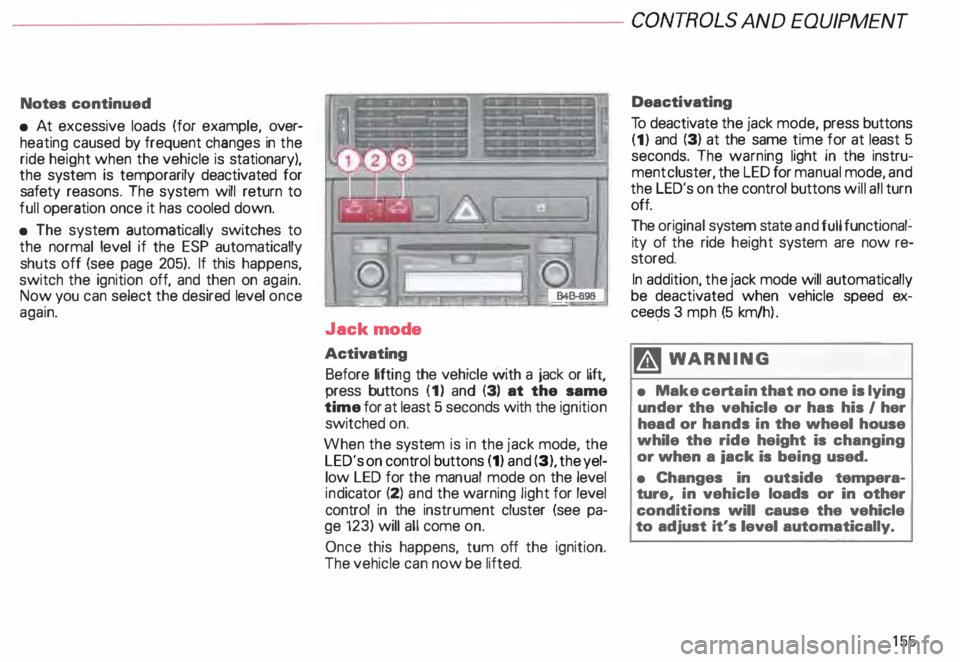
Jack mode
Activating Before lifting the vehicle with a jack or lift,
press buttons (1) and (3) at the same
time for at least 5 seconds with the ignition
switched on.
When the system is in the jack mode, the
LED's on control buttons (1) and (3), the yel
low LED for the manual mode on the level
ind icator (2) and the warning light for level
control in the instrument cluster (see pa
ge 123) will all come on.
Once this happens, tum off the ignition.
The vehicle can now be lifted. Deactivating
To deactivate the jack mode, press buttons
(1) and (3) at the same time for at least 5
seconds. The warning light in the instru
ment cluster, the LED for manual mode, and
the LED's on the control buttons will all turn
off.
The original system state and full functional�
ity of the ride height system are now re
stored.
In addition, the jack mode will automatically
be deactivated when vehicle speed ex
ceec;ls 3 mph (5 km/h ).
�W ARNING
• Make certain that no one is lying
under the vehicle or has his I her
head or hands in the wheel house
while the ride height is changing
or when a iack is being used.
• Changes in outside tempera
ture, in vehicle loads or in other
conditions will cause the vehicle
to adjust it's level automatically.
155
Page 163 of 306

CONTROLS AND EQUIPMENT---------------------
Cli
mate controls
�W ARNING
• For clear visibility and safe driv
ing, it is extremely important that
you follow the operating instruc
tions on the proper use and func
tion of the ventilation/heating, de
fogg ing{defr osting and air condi
tioning system in this manual. If in
doubt, consult your authorized
Audi Dealer.
• Good visibility comas with
clean windows free of fog, con
densation and frost.
• Maximum heating output and
fast defro sting will occur only af
ter the engine has reached operat
ing temperature. Wait until you
have good visibility before moving
your vehicle.
16 2 The
air conditioner is fully auto
matic, and is designed to maintain a com
fortable and uniform climate inside the ve
hicle .
The temperature of the air supplied to the in
terior, the fan speed, air distribution and vol
ume of air delivery are regulated automati
cally.
This automatic climate control program can
also be adjusted manually by the driver and
the front passenger.
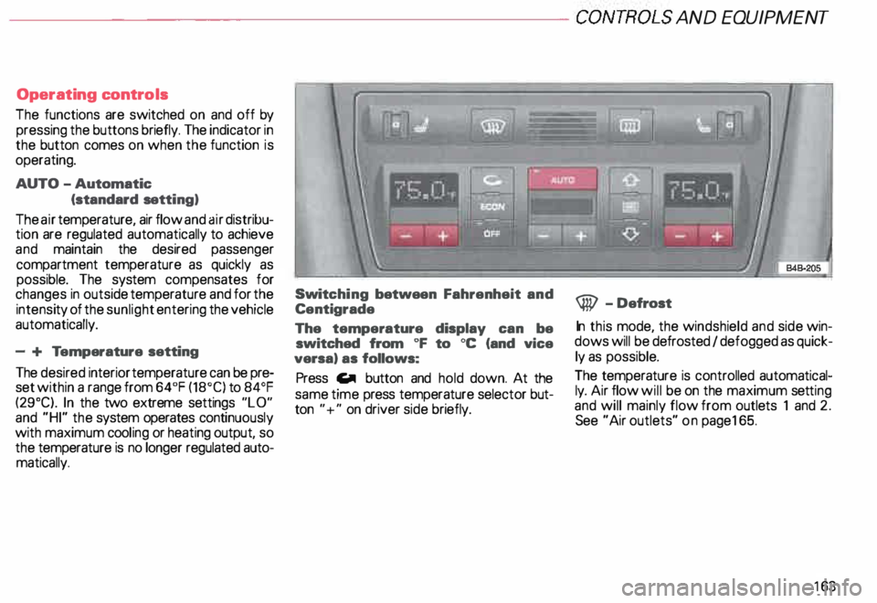
The illustration on the next page shows the
controls for the driver and front passenger
in the center console. The left display indi
cates the temperature selected for the driv
er's side and the right display the tempera
ture selected for the front passenger's side.
The temperature is selected by pressing the
"+" or "-" buttons beneath the respective
displays. Recommended
standard setting for
all-year operation:
After switching on the ignition
• Select a temperature of
75 oF (23°C) and
• Press AUTO button.
With this setting, you attain maximum com
fort in the least amount of time.
You only need to change this setting to
meet your personal needs.
Air outlets - see page 165.
Page 164 of 306

---------------------CONTROLS AND EQUIPMENT
Operating controls
The functions are switched on and off by
pressing the buttons briefly. The indicator in
the button comes on when the function is
operating.
AUTO -Automatic
(standard setting)
The air temperature, air flow and air distribu
tion are regulated automatically to achieve
and maintain the desired passenger
compartment temperature as quickly as
possible. The system compensates for
changes in outside temperature and for the
intensi ty of the sunlight entering the vehicle
automatically.
- + Temperature setting
The desired interior temperature can be pre
set within a range from 64°F (18°C) to 84°F
(29°C). In the two extreme settings "LO"
and "HI" the system operates continuously
with maximum cooling or heating output, so
the temperature is no longer regulated auto
matically. Swit
ching between Fahrenheit and
Centigrade
The temperature display can be
switched from oF to oc (and vice
versa) as follows:
Press Gill button and hold down. At the
same time press temperature selector but
ton "+" on driver side briefly. @
-Defrost
In this mode, the windshield and side win
dows will be defrosted I defogged as quick
ly as possible.
The temperature is controlled automatical
ly. Air flow will be on the maximum setting
and will mainly flow from outlets 1 and 2.
See "Air outlets" on pag e165.
163
Page 168 of 306

---------------------CONTROLS AND
EQUIPMENT
General notes
• Vehicle heating is depend upon tne tem
perature of the engine coolant -therefore,
your vehicle interior will warm uponly when
the engine has reached its operating tem
perature.
When the ambient temperature is too low,
the fan only switches to high speed modes
when the coolant has reached a sufficiently
high temperature, or when the ® button
has been depressed.
• Keeping the air intake slots in front of the
windshield free from ice, snow and debris
helps to make sure that the climate control
system will work properly.
• When the air conditioner compressor is
on it reduces both the temperature and the
humid ity of the air inside the vehicle. This
prevents the windows from fogging up.
• The air conditioner works best with the
windows and power roof* closed. •
If the inside temperature is very high af
ter the vehicle has been parked in the sun,
open windows and allow the hot air to es
cape before switching on the air condi
tioner.
• The dust and pollen filter will prevent
dust and pollen etc. in the outside air from
entering the car. Switch to air recirculation
to prevent unpleasant fumes from entering
the vehicle.
If water drips under the
vehicle ...
At high outside temperatures and humidity,
condensation may drip from the evaporator.
This is normal and does not indicate a leak.
If the airflow is not cool ...
• At low ambient temperatures the air con
ditioner compressor switches off automati
cally. The compressor cannot be switc hed
on again in this case, even by pressing the
AUTO button. •
The air conditioner may switch itself off
temporarily to ensure sufficient engine
cooling when the engine is running at full
load.
The air conditioner will also be switched off
temporarily in the kick-down function. See
page 109.
• Check the air conditioning fuse on the
fuse p imel -see page 27 4. Have it replaced,
if necessary.
• If you suspect that the air conditioner is
damaged, for instance after an accident,
switch to the ECON and have the system
examined immediately for leaks or other
damage.
167
Page 199 of 306

VE
HICL E OPER ATION ------------------------
• Tu rning off the ignition while the
vehicle is movin g-sea page 115 -or
• Other unusual operating condi
tions.
Do not continue to operate your ve
hicle under these conditions, as
otherwise fuel can reach the catalyt
ic converter. This could result in
overheating of the converter, requir
ing its replacement.
To assure eHiciant operation of the
Emission Control System:
• Have your vehicle maintained
properly and in accordance with the
service recommendations in your
Maintenance booklet.
Lack of proper maintenance as well
as improper usa of the vehicle will
impair the function of the emission
control system and could lead to
damage.
19 8 Cl
Do not alter or remove any com
ponent of the Emission Control Sys
ta.m unless approved by the
manufacturer.
• Do not alter or remove any device,
such as heat shields, switches, igni
tion wires, valves, which are de
signed to protect your vehicle 's
Emission Control System and other
important vehicle components.
Nota
Do not leave engine idling unat
tended after starting. If warning
lights should come on to indicate
improper operation, they would go
unheeded. Extended idling also pro
duces heat, which could result in
overheat ing or other damage to the
vehicle or other property. �W
ARNING
• Parking
Do not park or operate the vehicle
in areas where the hot exhaust sys
tem may coma in contact with dry
grass, brush, fuel spill or other ma
terial which can causa a fire.
• Undercoating
Do not apply additional undercoat
ing or rustproofing on or near the
exhaust manifold, exhaust pipes,
cata lytic converter or heat shields.
During driving, the substance
used for undercoating could over
heat and causa a fire.
Page 205 of 306

VE
HICL E OPERA TION-----------------------
'4 WARN ING continued
• Before descending a steep
grade, reduce speed and shift
transmission into a lower gear or
lower driving position. Do not ride
the brakes or hold the pedal down
too long or too often. This could
cause the brakes to get hot and di
minish braking efficiency.
• If you damage the front spoiler,
or if you install a different spoiler,
be sure the air flow to the front
brakes is not obstructed. Other
wise the brake system could over
heat reducing the effective ness of
the entire brake system.
• Failure of one brake circuit will
impair the braking capability re
sulting in an increased stopping
distance.
Avoid driving the vehicle and have
it towed to the nearest Audi Dealer
or qualified workshop.
204 Electronic differential lock
(EDL)
The EDL operates in conjunction with the
ABS. The EDL acts automatically, i.e. with
out the driver's intervention.
With the aid of the ABS sensors, this sy
stem monitors the speed of the driven
wheels up to about 50 mph, 80 km/h .
Within the speed range at which this sy
stem operates, if the wheels spin (e.g. on
slippery surfaces) they are braked in a con
trolled manner , and more of the engine's
power is directed to whiche ver wheels
achieve greater traction.
Please note:
• When driving off, always be sure to keep
road conditions in mind as you accelerate.
If a drive wheel spins because it's on a slip
perier surface, gradually increase the pres
sure on the accelerator pedal until the car
starts to move. •
When accelerating on slippery surfaces,
such as on ice or snow, always be careful
when depressing the accelerator pedal.
Even with the EDL working, the drive
wheels can spin and reduce your ability to
control your car.
• To prevent the disc brake of the braked
wheel from overheating, if subjected to ex
cessive loads the EDL cuts out temporarily.
The vehicle remains operational and be
haves in the same way as a vehicle without
EDL
If a fault occurs in the ABS the EDL is also
not functioning. This is ind icated by the ABS
warning light-see page 125.
ftl WARNING
The increased safety afforded by
EDL does not mean that you can
take safety risks. Always adapt
your driving style to the road con
ditions and traffic situation.