2000 AUDI ALLROAD change wheel
[x] Cancel search: change wheelPage 207 of 306

VEHICLE
OPER ATION----------------------
Operation
The Anti-Lock Brake System (ABS) and the
Electronic Differential Lock (EDU are inte
grat _ed in the Electronic Stability Progr am. In
a _ddrtron to the data provided by these func
tions, the ESP control unit requires addition
al measurement data provided by hig h-per
forman ?e sensors. The rotat ional speed of
the veh1cle about its vertical axis, vehicle lat
eral acceleration, brake pressure and the
steering angle are measured.
The direction in which the driverwishes to
travel is determined with the aid of the
stee �ing angle and the vehicle speed and is
contmually compared with the actual be
havior of the vehicle.
If the data do not match - for example when
a vehrcle is beginning to spin out of control
- the ESP applies the brakes to the appropri
ate wheels for the given situation and, if
necessar y, changes the vehicle traction
forces so as to reduce the slipping of individ
ual wheels (ASR anti-slip regulation).
206 The
vehicle is then stabilized by the forces
a ?tin � on the wheel during braking. If the ve
hicle IS overstee ring (rear tends to skid out
of the turn), the brakes are mainly applied on
the wheel that is on the outside ofthe curve.
In the case of a vehicle that is und ersteering
(tendency to slide out of the curve). the
brakes are applied at the rear wheel that is
on the inside of the curve. An audible signal
�rll accompany the brake application func
tion.
All �SP senso rs a�e monitored continuously
wh1le the vehicle IS being driven. However,
when the vehicle is driven at low speed on
ex tremely rugged terrain, it is not always
possrble to monrtor the ESP sensors contin
uously. Thus, in rare and exceptional cases
the ESP itself can deactivate (ESP and ABS
ind icator lights will be lit continuously).
In this case. the ride level adjustment sys
tem lowers the vehicle to the normal level
If this happens, you may need to select th�
ride level again (see page 153).
Operation of the ESP and ABS is restored
whenever you restart the engine. m
WAR NING
! he Electronic Stability Program
•• nevertheless subject to the laws
of physics. It is particularly impor
tant to pay attention to this fact on
wet and slippery roads.
It is therefore important that you
always adapt your driving to the
condition of the road and traffic
conditions. Do not allow the in
creased safety provided by the
Electro nic Stability Program sys
tem to lull you into accepting addi
tional safety risks.
Page 212 of 306
-----------------------VEHICL E OPER ATION
Tr ailer towing tips
Yo ur vehicle handles differently when tow
ing a trailer because of the additional weight
and weight distribution. Safety, perfor
mance and economy will greatly depend on
how carefully you load your trailer and oper
ate your rig.
Before you actually tow your trailer, practice
turning, stopping and backing up in an area
away from traffic until you learn the feel of
your vehicle and trailer unit.
Backing up is difficult and requir es practice.
Steering while backing up is generally oppo
site of that when backing your vehicle with
out a trailer.
Maintain a greater distance between your
vehicle and the one in front of you. You will
need more room to stop.
To compensate for the trailer, you will need
a larger than normal turning radius. When
passing, remember that you cannot
accelerate as fast as you normally would be
cause of the added load. Make sure you
have enough room to pass. After passing,
allow plenty of room for your trailer before
changing lanes again.
Avoid jerky starts, sharp turns or rapid lane
changes.
After parking, always block the wheels of
both vehicle and trailer. Do not park with a
trailer on a slope. If it cannot be avoided, do
so only after doing the following:
• Apply foot brake.
• Have someone place chocks under both
vehicle and trailer wheels.
• With chocks in place, slowly release
brakes until wheel blocks absorb the load.
• Turn wheels to curb.
o Apply parking brake.
• Place automatic transmission in "P". If
you move the selector lever of the auto
matic transmission to "P" before applying
the parking brake and before blocking the
wheels, you may require more force later to
move the lever out of the "P" position.
When restarting after parking on a slope, re
verse the procedure:
• Start the engine.
• Shift transmission into gear.
o Release the parking brake and slowly
move away from the wheel blocks.
• Stop and have someone retrieve the
wheel blocks.
Notes
• Do not tow a trailer during the
break-in period of your vehicle.
• If you tow a trailer, your Audi may require
more frequent maintenance due to the ex
tra load -see also page 228.
211
Page 256 of 306
Only
when tires show unusual wear such as
feather-e dging should they be rotated diag
� nall y. Yo ur vehicle may be equipped with
trres which have a specified rotation direc
tion. The rotation direction is identified by
arrow markings on the sides of the tires.
The rotation direction must not be revers ed.
Therefore, these tires cannot be switched
diagonally. If in doubt, discuss any unusual
tire wear with your authorized Audi Dealer's
service department.
After rotation adjust tire pressure and
torque wheel bolts diagonally to 90 tt lb
(120 Nm). Refer to "Changing a wheel" on
page 267 for details. Tire
replacement
Wheels and tires approved by the manu fac
turer have been specially matched to your
vehicle and contribute greatly to the road
holding, driving characteristics and safety of
the vehicle.
Make sure that the new tires also meet the
specifications listed on the label located on
the inside of the fuel filler flap or on the driv
er's door lock jamb.
It's �mporta nt to remember that in spite of
h �vrng the same tire designation, the actual
s1ze of a tire can vary from tire man ufacturer
to tire man ufacturer. Using different tire and
wheel rim combinations can result in re
duced clearance between the tire and the
vehicle body.
Therefore, never mount tires that
are of a different designation or
have different dimensions from
those of the factory supplied tires
which came equipped on your ve
hicle. VE
HICLE CARE
• If you must replace tires different from
those which were originally factory supplied
on your vehicle, always use the specific
brands, specifications and dimensions
which were specified by Audi for your ve
hicle.
Yo ur authorized Audi dealer or Audi Client
Relations have information regarding the
t1res and wheel rims specified for your car,
and can tell you which tires and tire
man ufacturers were approved by the fac
tory for original equipment installation.
• We recommend that you have your tires
changed by an authorized Audi Dealer, be
cause they have the special tools and nec
essary expertis e.
Furthermore, your authorized Audi Dealer
stocks a range of tires and wheels.
• If the spare tire is different from the tires
that you have mounted on your vehicle (for
example winter tires or wide profile tires),
then use the spare tire for a short period of
time only and drive with extra care. Replace
the flat tire with a tire matching the others
on your vehicle as soon as possible.
255
Page 268 of 306

•
The deflated full size spare tire cannot be
repaired or mounted using conventional
shop equipment. This work always has to
be performed by the man ufacturer of the
collapsible tire.
• All the air must be let out of the tire after
use before stowing it in the storage area
prov ided for it in the vehicle. Once all the air
is out, the tire will return to its original form.
To let the air out of the tire, either use a
sharp object to press down on the metal pin
in the valve, or use the valve-remo ving tool
on the back side of the dust cap to unscrew
the valve stem. Changing
a wheel
�W ARNING
You or your passengers could be
injured while changing a wheel if
you do not follow safety precau
tions:
• If you have a flat tire, move a
safe distance off the road. Turn off
the engine, turn the emergency
flasher on and use other warning
devices to alert other motorists.
• Passengers must not rema in in
the vehicle when it is jacked up.
This includes children as well as
adults.
• Make sure that passengers wait
in a safe place away from the ve
hicle and well away from the road
way and traffic.
• Before you change a wheel, be
sure the ground is level and firm.
If necessary, use a sturdy board
under the jack. DO-IT-YOURSELF
SERVICE
�� WARN ING continued
• After installing the spare wheel,
make sure that you remount the
flat tire/Wheel in its storage area
properly and tighten the plastic
knurled screw securely.
• To help prevent the vehicle from
moving suddenly and possibly
slipping off the jack, always fully
set the parking brake and block
the wheel diagonally opposite the
wheel being changed. When one
front wheel is lifted off the
ground, placing the automatic
transmission in P (Park) will not
prevent vehicle movement.
267
Page 269 of 306
DO-IT-Y
OURSELF SERVICE----------------------
Step 1 ·"7
r.-&
.--· t I . ... ,.. . . . --------� .... ... . . ...
-
' . .. . ...
.. - - . .
J
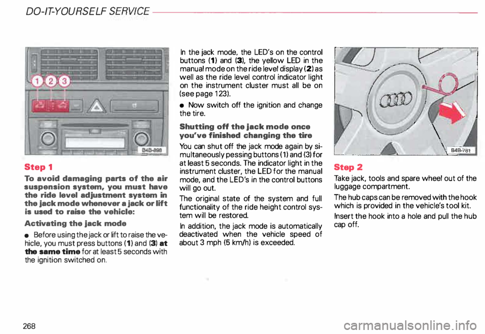
To avoid damaging parts of the air
suspension system. you must have
the ride level adjustment system in
the jack mode whenever a jack or lift
is used to raise the vehicle:
Activati ng the jack mode
• Before using the jack or lift to raise the ve
hicle, you must press buttons (1) and (3) at
the same time for at least 5 seconds with
the ignition switched on.
268 In
the jack mode. the LED's on the control
buttons (1) and (3), the yellow LED in the
manual mode on the ride level display (2) as
well as the ride level control indicator light
on the instrument cluster must all be on
(see page 123).
• Now switch off the ignition and change
the tire.
Shutting off the jack mode once
you've finished changing the tire
Yo u can shut off the jack mode again by si
mu ltaneously pessing buttons (1) and (3) for
at least 5 seconds. The indicator light in the
instrument cluster, the LED for the manual
mode, and the LED's in the control buttons
will go out.
The original state of the system and full
functionality of the ride height control sys
tem will be restored.
In addition, the jack mode is automatically
deactivated when the vehicle speed of
about 3 mph (5 km/h) is exceeded. Step
2
Ta ke jack, tools and spare wheel out of the
luggage compartment.
The hub caps can be removed with the hook
which is provided in the vehicl e's tool kit.
Insert the hook into a hole and pull the hub
cap off.
Page 270 of 306
----------------------DO-IT-YOURSELF SERVICE
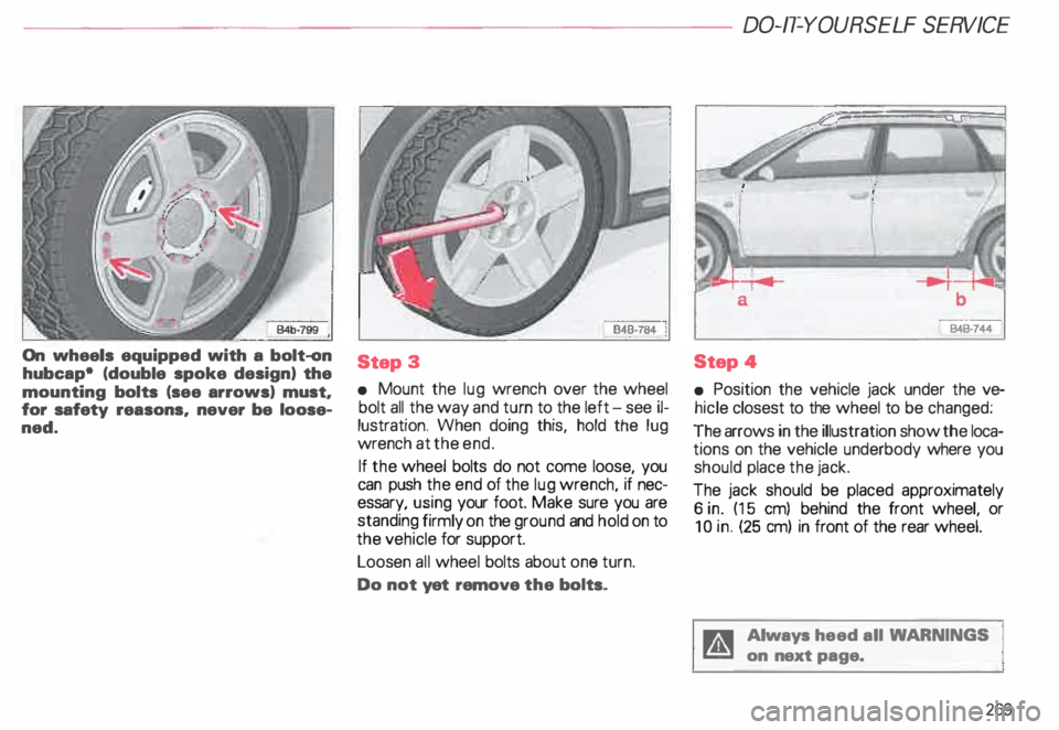
On wheels equipped with a bolt-on
hubcap• (double spoke design) the
mounting bolts (see arrows) must,
for safety reasons, never be loose
ned. Step
3
• Mount the lug wrench over the wheel
bolt all the way and turn to the left - see il
lustration. When doing this, hold the lug
wrench at the end.
If the wheel bolts do not come loose, you
can push the end of the lug wrench, if nec
essary, using your foot. Make sure you are
standing firmly on the ground and hold on to
the vehicle for support.
Loosen all wheel bolts about one turn.
Do not yet remove the -bolts . B4B·744
Step 4
• Position the vehicle jack under the ve
hicle closest to the wheel to be changed:
The arrows in the illustration show the loca
tions on the vehicle underbody where you
should place the jack.
The jack should be placed approximately
6 in. (15 em) behind the front wheel, or
10 in. (25 em) in front of the rear wheel.
Always heed all WA RNINGS
on next page.
269
Page 271 of 306
DO-IT-Y
OURSELF SERVICE----------------------
\
�W ARNING
Yo u or your passengers could be
injured while changing a wheel if
you do not follow safety precau
tions:
• Jacking at any other place may
damage the vehicle or may result
in personal injuries.
• An unstable surface under the
jack may cause the vehicle to slip
off the jack. Always provide a firm
base for the jack on the ground. If
necessa ry. use a sturdy board un
der the jack.
• On hard. slippery surface (such
as tiles) use a rubber mat or similar
to prevent the jack from slipping.
270 Step
5
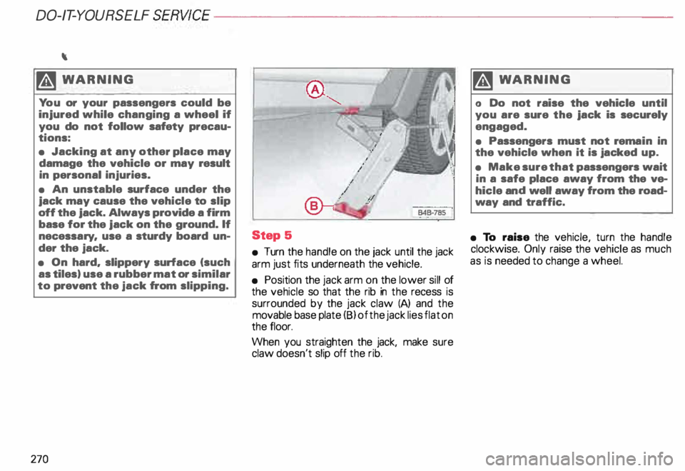
• Turn the handle on the jack until the jack
arm just fits underneath the vehicle.
• Position the jack arm on the lower sill of
the vehicle so that the rib in the recess is
surrounded by the jack claw (A) and the
movable base plate (8) of the jack lies flat on
the floor.
When you straighten the jack, make sure
claw doesn't slip off the rib. �W
ARNING
o Do not raise the vehicle until
you are sure the jack is securely
engaged.
• Passengers must not rema in in
the vehicle when it is jacked up.
• Make sure that passengers wait
in a safe place away from the ve
hicle and well away from the road
way and traffic.
• To raise the vehicle, turn the handle
clockwise. Only raise the vehicle as much
as is needed to change a wheel.
Page 273 of 306

DO-IT-Y
OURSELF SERVICE----------------------
Step
7
Inflating the deflated full size
spare tire
• Remove the dust cap from the valve (1 l
by unscrewing it.
• Take the pressure compressor hose out
of the case, and screw the coupling nut se
curely onto the valve.
• Insert the compressor· connector in to
the socket located on the side of the lug
gage compartment or inset it ino the ciga
rette lighter socket -see page 181.
272 •
Turn on the compressor. The required tire
pressure wil be reached within a few min
utes. Use a pressure gauge to check the tire
pressure. Never operate the compressor
for longer than 5 minutes.
Note
Yo u'll find adhesive labels on the deflated
full size spare tire containing i nstn .1ctions for
using the tire as well as information on the
specified tire pressure.
Step S
• Un screw the pressure hose from the val
ve and screw the dust cap back on.
• To lower the vehicle, turn the handle
counter-clockwise until the jack is fully re
leased. Remove jack.
• Then go crosswise from one bolt to
another tightening them firmly.
• If necessary, press the hubcap back onto
the hub of the spare wheel. Step
9
• Slip the plastic cover over the wheel con
taining the flat tire. Then stow this wheel in
the luggage comopartment and secure it so
that it does not shift.
• Carefully observe the points on
page 288 when using the deflated
full size spare tire.
Notes
• The hex socket in the screwdriver can be
used to make it easier to handle the wheel
bolts. To do this, pull out the revers ible bla-
de. ·
Never use this plastic tool to loosen
or tighten the wheel bolts.
After you change a tire:
• Deactivating the jack moda -see
page 268.
• Use a torque wrench to check the
wheel bolt tightening torque as
soon as possible. With alloy wheels
and a deflated full size spare tire, the
torque should be 88.5 ft-lb (120
Nm).