2000 AUDI ALLROAD ignition
[x] Cancel search: ignitionPage 250 of 306

-------------------------VEHICLE
CARE
Spark plugs
Spark plugs are replaced during the Audi
scheduled Maintenance Service.
If you have to replace the spark plugs be
tween the Audi Maintenance services, be
sure to note the following:
• Engine, spark plugs and the ignition sys
tem are matched to each other. To avoid
faulty operation or engine damage, use only
Original Audi spark plugs. It is especially im
portant to note the number of electrodes on
the spark plug and the heat value.
• Since spark plug specifications may
change for technical reasons during a model
year, we recommend that you obtain your
spark plugs from an authorized Audi Dealer,
who has the latest information.
Always heed all WARNINGS
on page 232. Belts
Ribbed V-Belt
The radiator fan, hydraulic pump (power
steering), alternator and air conditioner
compressor are driven by one V-belt.
The installed V-belt conforms to the highest
quality requirements. The V-belt adjusts its
own tension.
Replacing of the V-belt should be
performed by your authorized Audi
Dealer or a qualified workshop.
When replacing a belt, it is not sufficient to
use just any belt of the same size. For safe
and reliable operation, use only Genuine
Audi V-belts specially designed for your ve
hicle. The correct belts can be obta ined at
your authorized Audi Dealer. �W
ARNING
To prevent serious personal inju
ries stay well clear of the V-belt,
The radiator fan and the V-belt
driven accessories when the en
gine is running. The V-belt will be
inspected and replaced by your au
thorized Audi Dealer during a
scheduled Maintenance Service.
Timing belt
• Yo ur engine is equipped with a long last
ing toothed belt. The belt will be in
spected and replaced during a scheduled
Maintenance Service.
Always heed all WA RNINGS
on page 232.
249
Page 269 of 306

DO-IT-Y
OURSELF SERVICE----------------------
Step 1 ·"7
r.-&
.--· t I . ... ,.. . . . --------� .... ... . . ...
-
' . .. . ...
.. - - . .
J
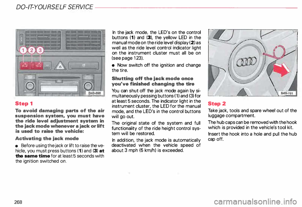
To avoid damaging parts of the air
suspension system. you must have
the ride level adjustment system in
the jack mode whenever a jack or lift
is used to raise the vehicle:
Activati ng the jack mode
• Before using the jack or lift to raise the ve
hicle, you must press buttons (1) and (3) at
the same time for at least 5 seconds with
the ignition switched on.
268 In
the jack mode. the LED's on the control
buttons (1) and (3), the yellow LED in the
manual mode on the ride level display (2) as
well as the ride level control indicator light
on the instrument cluster must all be on
(see page 123).
• Now switch off the ignition and change
the tire.
Shutting off the jack mode once
you've finished changing the tire
Yo u can shut off the jack mode again by si
mu ltaneously pessing buttons (1) and (3) for
at least 5 seconds. The indicator light in the
instrument cluster, the LED for the manual
mode, and the LED's in the control buttons
will go out.
The original state of the system and full
functionality of the ride height control sys
tem will be restored.
In addition, the jack mode is automatically
deactivated when the vehicle speed of
about 3 mph (5 km/h) is exceeded. Step
2
Ta ke jack, tools and spare wheel out of the
luggage compartment.
The hub caps can be removed with the hook
which is provided in the vehicl e's tool kit.
Insert the hook into a hole and pull the hub
cap off.
Page 275 of 306

DO-IT-YOURSELF
SERVICE----------------------
Fuses
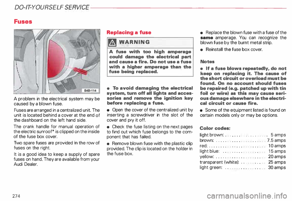
A problem in the electrical system may be
caused by a blown fuse.
Fuses are arranged in a centra lized unit. The
unit is located behind a cover at the end of
the dash board on the left hand side.
The crank handle for manual operation of
the electric sunroof* is cli pped on the inside
of the fuse box cover.
Two spare fuses are provided in the row of
fuses on the right.
It is a good idea to keep a supply of spare
fuses on hand. They are available from your
Audi Dealer.
274 Replacing
a fuse
� WARNING
A fuse with too high amperage
could damage the electrical part
and cause a fire. Do not use a fuse
with a higher amperage than the
fuse being replaced. ·
• To avoid damaging the electrical
system. turn off all lights and acces
sories and remove the ignition key
before replacing a fuse.
• Open the cover of the centralized unit by
inserting a screwdriver in the slot of the
cover and pry it off.
• Check the fuse listing on the next pages
to find out which fuse belongs to the com
ponent that has failed.
• Remove blown fuse with the plastic clip
prov ided. The clip is located on the holder in
the fuse box. •
Replace the blown fuse with a fuse of the
same amperage. You can recognize the
blown fuse by the burnt metal strip.
• Reinstall the fuse box cover.
Notes
• If a fuse blows repeatedly. do not
keep on replacing it. The cause of
the short circuit or overload must be
found. On no account should fuses
be repaired (e.g. patched up with tin
foil or wire) as this may cause seri
ous damage elsewhere in the electri
cal circuit or cause fire.
• Some of the equipment listed is found on
certa in models only or may be options.
Color codes:
light brown: . .
... • _ .. .. . __ . _ . 5 amps
brown: .... .
red: ....... .
light blue: ..
yellow: .....
transparent (white): ..•
light green: .. _
7.5 amps
10 amps
15 amps
20 amps
25 amps
30 amps
Page 285 of 306

DO-IT-YOURSELF
SERVICE----------------------
Jack
mode
Activat ing
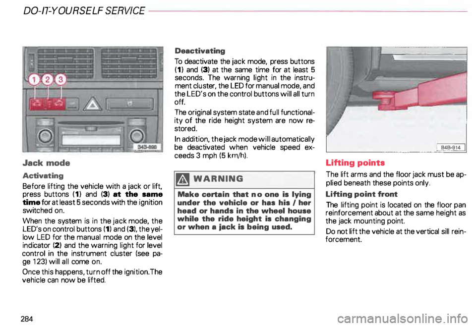
Before lifting the vehicle with a jack or lift,
press buttons (1) and (3) at the same
time for at least 5 seconds with the ignition
switc hed on.
When the system is in the jack mode, the
LED's on control buttons (1) and (3), the yel
low LED for the manual mode on the level
ind icator (2) and the warning light for level
control in the instrument cluster (see pa
ge 123) will all come on.
Once this happens, turn off the ignition. The
vehicle can now be lifted.
284 Deactivating
To deactivate the jack mode, press buttons
(1) and (3) at the same time for at least 5
seconds. The warning light in the instru
ment cluster, the LED for manual mode, and
the LED's on the control buttons will all turn
off.
The original system state and full functional
ity of the ride height system are now re
store d.
In addition, the jack mode will automatically
be deactivated when vehicle speed ex
ceeds 3 mph (5 krn/h).
.� WARNING
Make certain that no one is lying
under the vehicle or has his I her
head or hands in the wheel house
while the ride height is changing
or when a iack is being used. Lifting points
The
lift arms and the floor jack must be ap
plied beneath these points only.
Lifting point front
The lifting point is located on the floor pan
reinforcement about at the same height as
the jack mounting point.
Do not lift the vehicle at the vertical sill rein
forcement.
Page 292 of 306

The
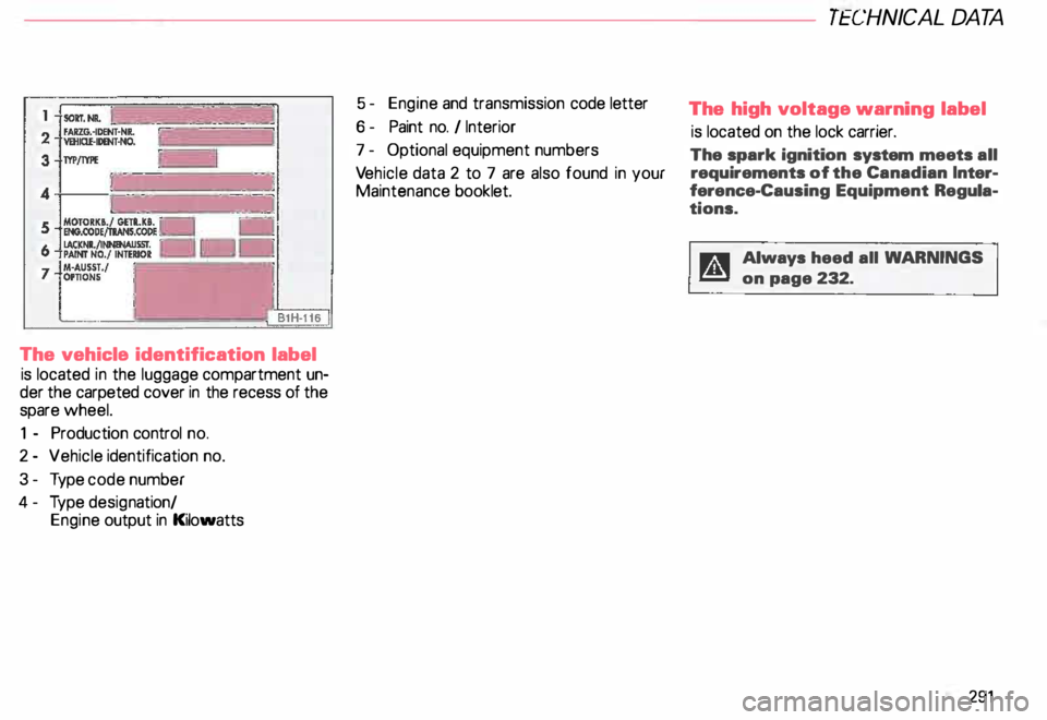
vehicle identification label
is located in the luggage compartment un
der the carpeted cover in the recess of the
spare wheel.
1 - Production control no.
2 - Vehicle identification no.
3- Type code number
4- Type desig nation/
Engine output in Kilowatts 5 -
Engine and transmission code letter
6- Paint no. I Interior
7 - Optional equipment numbers
Ve hicle data 2 to 7 are also found in your
Maintenance booklet. TECHNICA
L DA TA
The high voltage warning label
is located on the lock carrier.
The spark ignition system meets all
requirements of the Canadian Inter
ference- Causing Equipment Regula
tions. D Always heed all WARNlNGS
f!!l on page 232.
291
Page 300 of 306

- Capacities
. . . • . . . . . . . . • . . . 287
-C oolant . . . . . . . .
238
-W indshield washer tank . . . . 250
Fog lights .. .. .. .. .
. 149
Folding master key _ . . . . . . • . . 56
Four- Wheel Drive . . . . . • • . . 207
Front airbags .
. . . • • • . . . 25
Front axle load . . . • • . • • • . 289
Front fog lights .... ... .... .. .. 149
Front seats . . . . . . . . . . . . . . . . . . . . 76
Fuel -Tank capacity . . . . . . . . . . 222
Fuel economy . . . . . . . . . • . 19
5
Fuel gauge . . . . • • . . . .
119
Fuel supply . . . . . . . . . . . . . • . . . . . 225
Fuel tank . . . . . • . . . . . . . . 222
- Capacity
. • . • • . . • . . • • • . . 287
Fuses . . . •
... .•.. .• • .. . .. 274
G
Garage door opener ...• , • . . . . 173
Gas discharge lamps . . .
277
Gasoline additives . . . . .
227
Gauges and instruments
- Coolant temperature 118 -
Engine oil temperature
-F uel ........ . ..
117
.. 119
- Odometer . . . . . • . . • . . • . . . 11 9
- Speedometer . • . . . . . . . . . . 119
-T achome ter .. _. _...... ... 117
General illustration .
. . . . 8
Gen erator ....... ..... .
Glove box light ... .
Glo ve compartment . . . .
Ground clearance ... . _ .. 12
0, 127
17 8
17 8
153
Gross axle weight rating ...... . 289
289
Gross vehicle weight rating .... .
H
Head airbags . • . • . . • • • .•. . . 39
Head restraints . . . . • . . . . . 75
Headlight adjustment . . • . • • .
148
Headlight dimmer .....• , • . . . .
156
Headlight flasher . . . . . . . . . . . • . . 157
Headlights -Cleaning . .
214
Heated seats . . . . . . . . .
150
Heated steering wheel . 150
Heating . . . . . . . . . . . . . . 162
High beam . . . . . . . . . . . • . . . . . . 12
5 ALP
HABETIC AL INDE X
High voltage label
. . . . . • • . • 291
Hood release . . .
231
Hooks . . . . . . . . . • • • • • . .
.. 89
Horn . . . . . . . . . . . • • • . _ .. . .. .. . . . 8
Hydropla ning . . . . 195, 207
I
Identification label ..
291
Identification number ....... ... 290
Ign ition .................. ... 113
Ignition key safety interlock ..... 104
Immobilize r............. 57,
124
Increasing size of luggage
compartment ..... .
Ind icator lights ...... .
Infant seats .......... .
Inside day-night mirror
Installing a radio ..... .
Installing a roof rack ..
Installing wiper blades
Instru ment cluster .... ....
88
10, 122
. 45
. 72
277
191
. . .. -... 251
. . 116
Ins trument illumination . 14 9
Instrument panel . . . . .
. . . 8
Interior lights . . . . . . . . . . . . . . . 171