Page 57 of 71
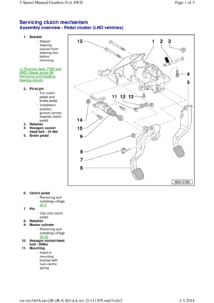
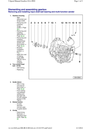
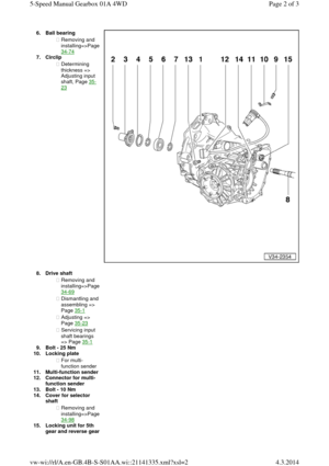
Dismantling and assembling gearbox Removing and installing input shaft ball bearing, multi-function sender, input
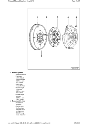
shaft, drive pinion, selector rods, gearbox cover and cover with Torsen differential Special tools and workshop
equipment required
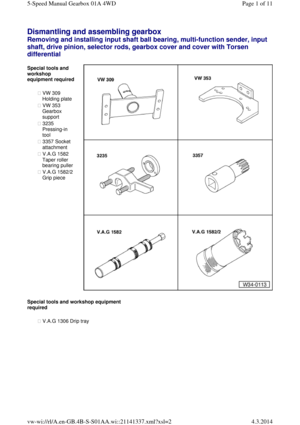
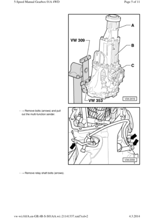
◆ VW 309
Holding plate
◆ VW 353
Gearbox
support
◆ 3235
Pressing-in
tool
◆ 3357 Socket
attachment
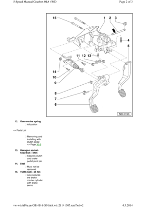
◆ V.A.G 1582
Taper roller
bearing puller
◆ V.A.G 1582/2
Grip piece Special tools and workshop equipment required
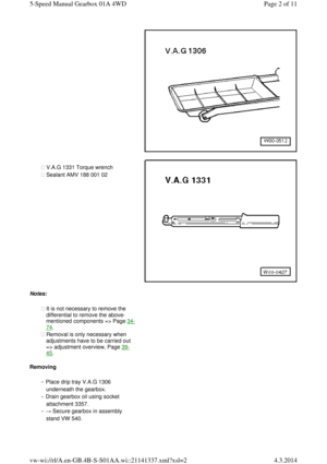
◆ V.A.G 1306 Drip tray Page 1 of 115-Speed Manual Gearbox 01A 4WD4.3.2014vw-wi://rl/A.en-GB.4B-S-S01AA.wi::21141337.xml?xsl=2
Page 58 of 71
◆ V.A.G 1331 Torque wrench
◆ Sealant AMV 188 001 02 Notes:
◆ It is not necessary to remove the
differential to remove the above-
mentioned components => Page 34-74.
◆ Removal is only necessary when
adjustments have to be carried out
=> adjustment overview, Page 39-45.
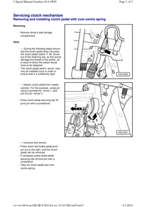
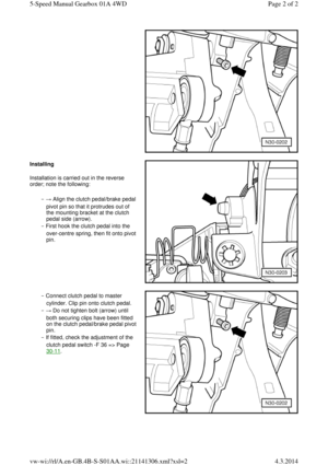
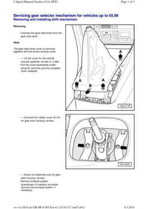
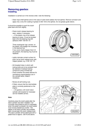
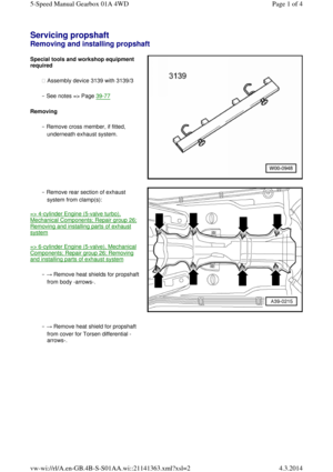
Removing
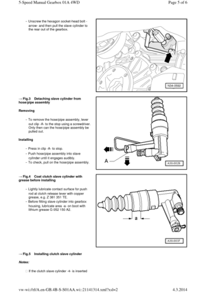
‒ Place drip tray V.A.G 1306
underneath the gearbox.
‒ Drain gearbox oil using socket
attachment 3357.
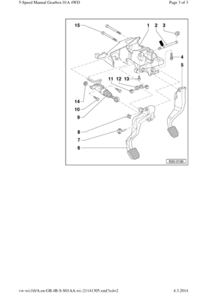
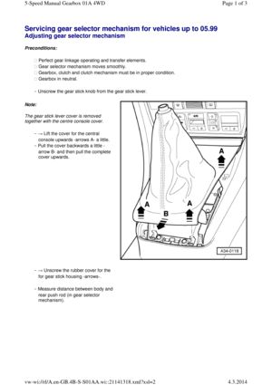
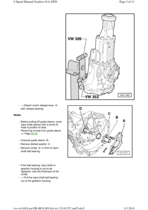
‒ → Secure gearbox in assembly
stand VW 540. Page 2 of 115-Speed Manual Gearbox 01A 4WD4.3.2014vw-wi://rl/A.en-GB.4B-S-S01AA.wi::21141337.xml?xsl=2
Page 59 of 71
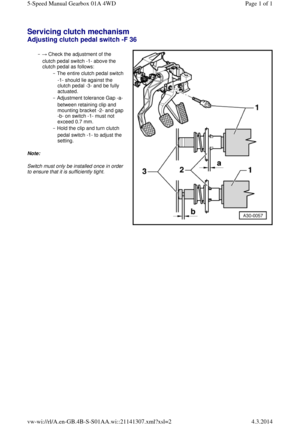
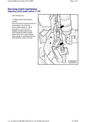
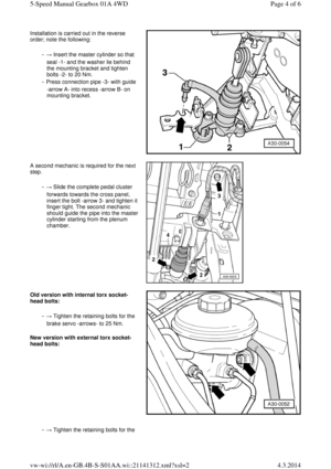
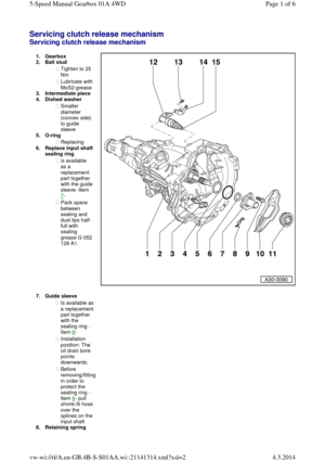
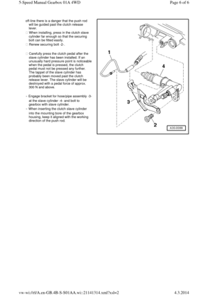
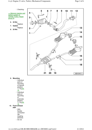
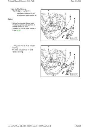
‒ → Detach clutch release lever -A-
with release bearing.
Notes:
◆ Before pulling off guide sleeve, cover input shaft splines with a shrink-fit
hose to protect oil seal.
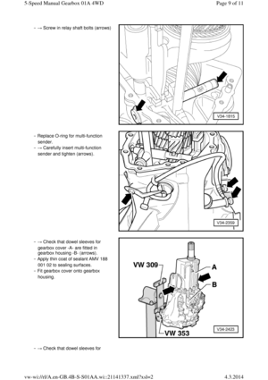
◆ Removing oil seal from guide sleeve
=> Page 30-32.
‒ Unscrew guide sleeve -B-.
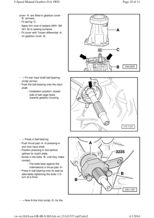
‒ Remove dished washer -C-.
‒ Remove circlip -D- in front of input
shaft ball bearing. ‒ If the ball bearing, input shaft or
gearbox housing is not to be
replaced, note the thickness of the
circlip.
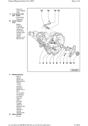
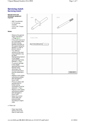
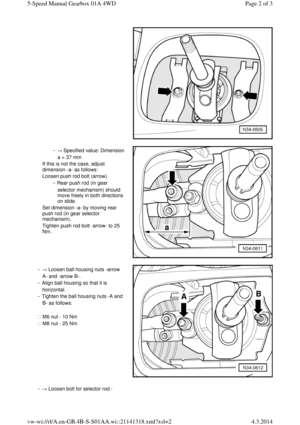
‒ → Pull the input shaft ball bearing
out of the gearbox housing. Page 3 of 115-Speed Manual Gearbox 01A 4WD4.3.2014vw-wi://rl/A.en-GB.4B-S-S01AA.wi::21141337.xml?xsl=2
Page 60 of 71
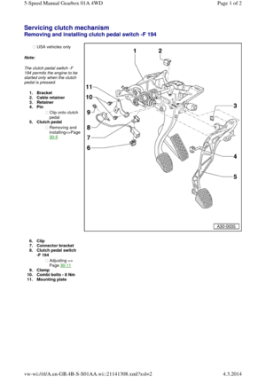
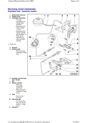
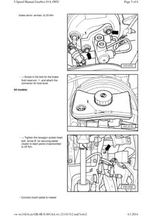
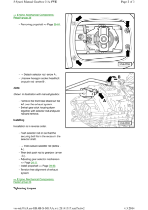
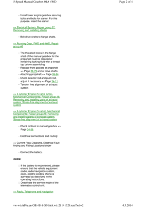
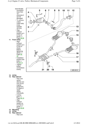
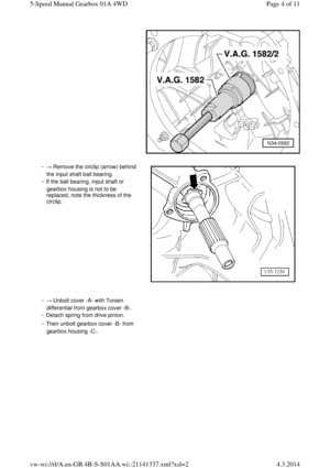
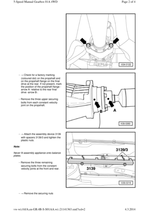
‒ → Remove the circlip (arrow) behind
the input shaft ball bearing.
‒ If the ball bearing, input shaft or
gearbox housing is not to be
replaced, note the thickness of the
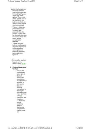
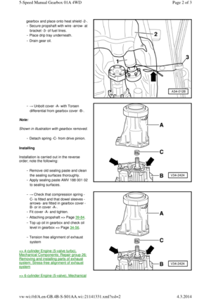
circlip. ‒ → Unbolt cover -A- with Torsen
differential from gearbox cover -B-.
‒ Detach spring from drive pinion.
‒ Then unbolt gearbox cover -B- from
gearbox housing -C-. Page 4 of 115-Speed Manual Gearbox 01A 4WD4.3.2014vw-wi://rl/A.en-GB.4B-S-S01AA.wi::21141337.xml?xsl=2
Page 61 of 71
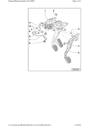
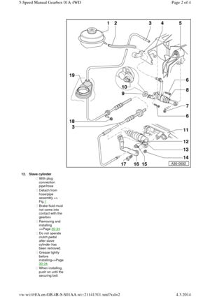
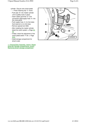
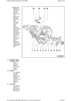
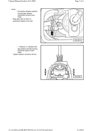
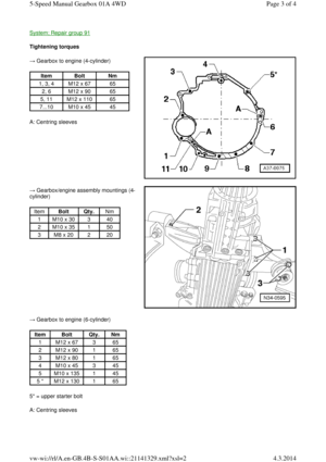
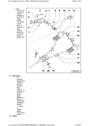
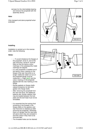
‒ → Remove bolts (arrows) and pull
out the multi-function sender. ‒ → Remove relay shaft bolts (arrows). Page 5 of 115-Speed Manual Gearbox 01A 4WD4.3.2014vw-wi://rl/A.en-GB.4B-S-S01AA.wi::21141337.xml?xsl=2
Page 62 of 71
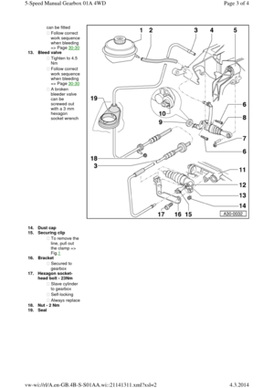
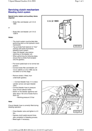
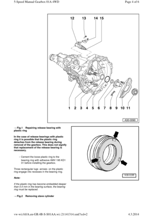
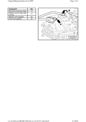
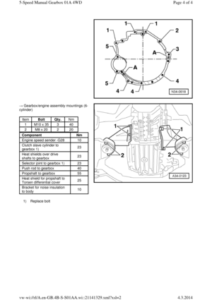
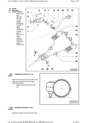
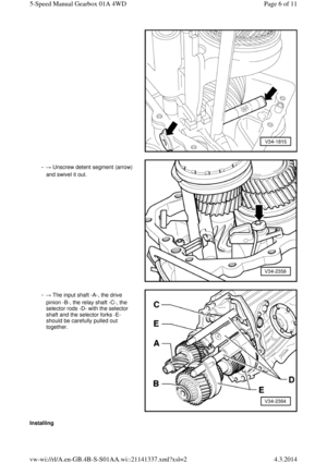
‒ → Unscrew detent segment (arrow)
and swivel it out. ‒ → The input shaft -A-, the drive
pinion -B-, the relay shaft -C-, the
selector rods -D- with the selector
shaft and the selector forks -E-
should be carefully pulled out
together. Installing Page 6 of 115-Speed Manual Gearbox 01A 4WD4.3.2014vw-wi://rl/A.en-GB.4B-S-S01AA.wi::21141337.xml?xsl=2
Page 63 of 71
Note: If the input shaft ball bearing, the input shaft or the gearbox housing are renewed, it is
necessary to re-determine the thickness of
the circlips for the input shaft =>Page 35-23, adjusting input shaft.
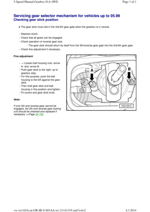
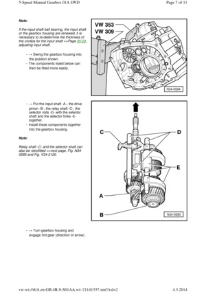
‒ → Swing the gearbox housing into
the position shown.
‒ The components listed below can
then be fitted more easily. ‒ → Put the input shaft -A-, the drive
pinion -B-, the relay shaft -C-, the
selector rods -D- with the selector
shaft and the selector forks -E-
together.
‒ Install these components together
into the gearbox housing.
Note:
Relay shaft -C- and the selector shaft can
also be retrofitted =>next page, Fig. N34-
0585 and Fig. V34-2120. ‒ → Turn gearbox housing and
engage 3rd gear (direction of arrow). Page 7 of 115-Speed Manual Gearbox 01A 4WD4.3.2014vw-wi://rl/A.en-GB.4B-S-S01AA.wi::21141337.xml?xsl=2
Page 64 of 71
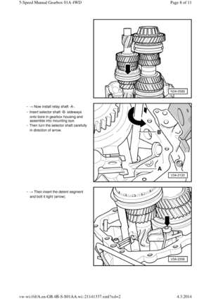
‒ → Now install relay shaft -A-.
‒ Insert selector shaft -B- sideways
onto bore in gearbox housing and
assemble into mounting eye.
‒ Then turn the selector shaft carefully
in direction of arrow. ‒ → Then insert the detent segment
and bolt it tight (arrow). Page 8 of 115-Speed Manual Gearbox 01A 4WD4.3.2014vw-wi://rl/A.en-GB.4B-S-S01AA.wi::21141337.xml?xsl=2


 behind
the input shaft ball bearing.
‒ If the ball bearing, input shaft or
gearbox housing is not to be
replaced, note the thickness of the
circlip. ‒ �")
 and pull
out the multi-function sender. ‒ → Remove relay shaft bolts (arrows). Page 5 of 115-Speed Manual Gearbox 01A 4WD4.3.2014vw-wi://rl/A.en-GB.4B-S-S01AA.wi:")

and swivel it out. ‒ → The input shaft -A-, the drive
pinion -B-, the relay shaft -C-, the
selector rods -D- with the selector
shaft and the selector")

