Page 49 of 71
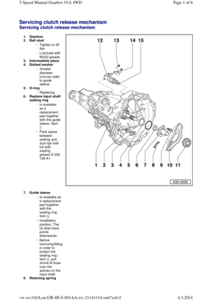
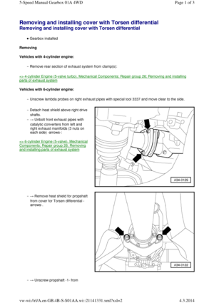
◆ Checking: => Motronic injection and ignition system (4 cylinder Turbo); Repair group 24
6.25 Nm
◆ Replace
7.Gasket
◆ Replace
8.25 Nm 9.Mounting ◆ Individual
parts of
mounting
of manual
gearbox
=> Fig.26-15
◆ Individual
parts of
mounting
of
automatic
gearbox
=> Fig.26-16
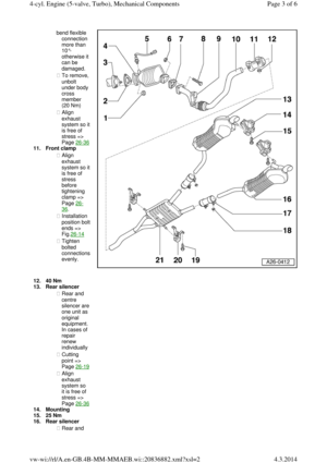
10.Front exhaust
pipe
◆ With
flexible
connection
(de
coupling
element)
◆ Do not Page 2 of 64-cyl. Engine (5-valve, Turbo), Mechanical Components4.3.2014vw-wi://rl/A.en-GB.4B-MM-MMAEB.wi::20836882.xml?xsl=2
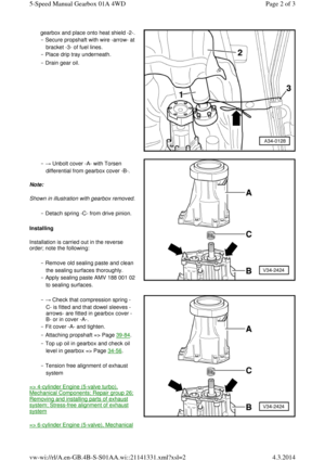
Page 50 of 71
bend flexible
connection
more than
10°-
otherwise it
can be
damaged.
◆ To remove, unbolt
under body
cross
member
(20 Nm)
◆ Align
exhaust system so it is free of
stress =>
Page 26-36 11.Front clamp
◆ Align
exhaust system so it is free of
stress
before
tightening
clamp =>
Page 26-36.
◆ Installation position bolt ends =>
Fig.26-14
◆ Tighten
bolted connections evenly. 12.40 Nm 13.Rear silencer
◆ Rear and
centre silencer are one unit as
original equipment. In cases of
repair
renew
individually
◆ Cutting
point =>
Page 26-19◆ Align
exhaust
system so
it is free of
stress =>
Page 26-3614.Mounting
15.25 Nm
16.Rear silencer
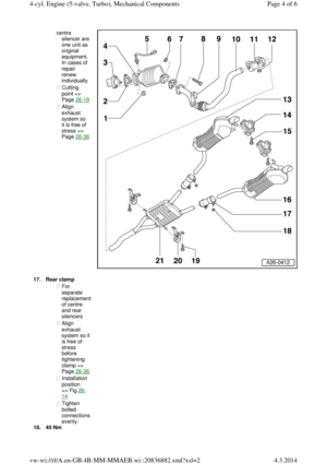
◆ Rear and Page 3 of 64-cyl. Engine (5-valve, Turbo), Mechanical Components4.3.2014vw-wi://rl/A.en-GB.4B-MM-MMAEB.wi::20836882.xml?xsl=2
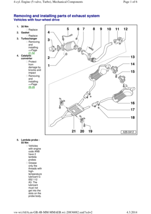
Page 51 of 71
centre silencer are one unit as
original equipment. In cases of
repair
renew
individually
◆ Cutting
point =>
Page 26-19◆ Align
exhaust
system so
it is free of
stress =>
Page 26-36 17.Rear clamp ◆ For
separate replacement of centre
and rear
silencers
◆ Align
exhaust system so it is free of
stress
before
tightening
clamp =>
Page 26-36. ◆ Installation
position
=> Fig.26-14
◆ Tighten
bolted connections evenly.
18.40 Nm Page 4 of 64-cyl. Engine (5-valve, Turbo), Mechanical Components4.3.2014vw-wi://rl/A.en-GB.4B-MM-MMAEB.wi::20836882.xml?xsl=2
Page 52 of 71
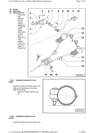
19.25 Nm 20.Mounting
21.Centre silencer
◆ Centre and rear
silencers
are one
unit as
original equipment. In cases of
repair
renew
individually
◆ Cutting
point =>
Page 26-19◆ Align
exhaust
system so
it is free of
stress =>
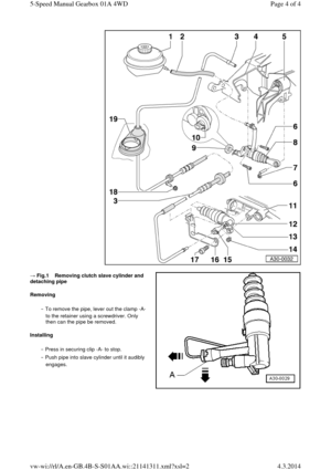
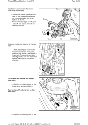
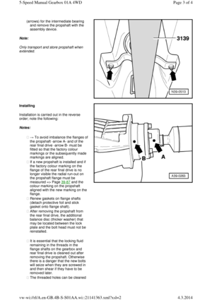
Page 26-36 → Fig.1 Installation position of front clamp
‒ Install the clamps so that the ends of the bolts do not protrude over the lower
edge of the clamp.
‒ Bolted connection facing to the
left
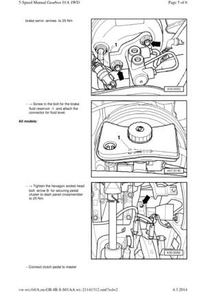
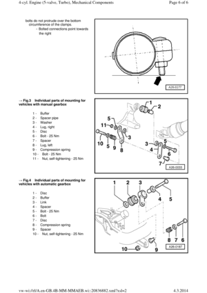
→ Fig.2 Installation position of rear clamps
‒ Install the clamps so that the ends of the Page 5 of 64-cyl. Engine (5-valve, Turbo), Mechanical Components4.3.2014vw-wi://rl/A.en-GB.4B-MM-MMAEB.wi::20836882.xml?xsl=2
Page 53 of 71
bolts do not protrude over the bottom
circumference of the clamps.
‒ Bolted connections point towards
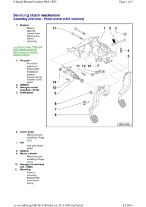
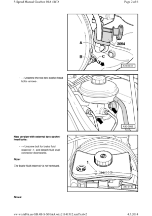
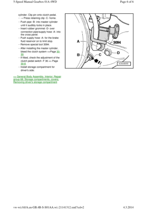
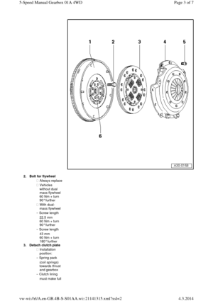
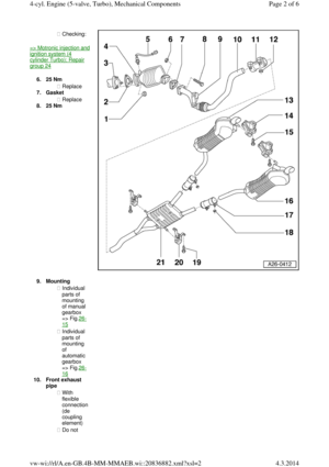
the right → Fig.3 Individual parts of mounting for vehicles with manual gearbox
1 - Buffer
2 - Spacer pipe
3 - Washer
4 - Lug, right
5 - Disc
6 - Bolt - 25 Nm
7 - Spacer
8 - Lug, left
9 - Compression spring
10 - Bolt - 25 Nm
11 - Nut, self-tightening - 25 Nm
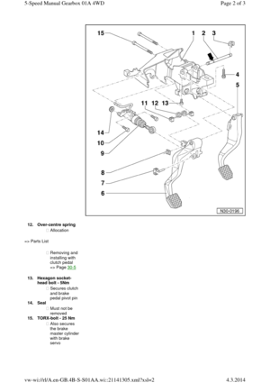
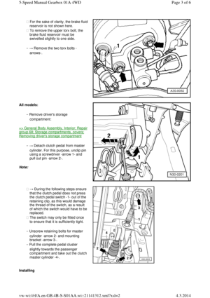
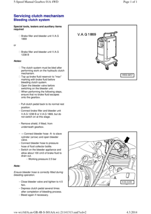
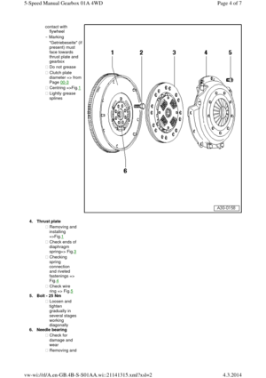
→ Fig.4 Individual parts of mounting for vehicles with automatic gearbox
1 - Disc
2 - Buffer
3 - Link
4 - Spacer
5 - Bolt - 25 Nm
6 - Bolt
7 - Disc
8 - Compression spring
9 - Spacer
10 - Nut, self-tightening - 25 Nm Page 6 of 64-cyl. Engine (5-valve, Turbo), Mechanical Components4.3.2014vw-wi://rl/A.en-GB.4B-MM-MMAEB.wi::20836882.xml?xsl=2
Page 54 of 71
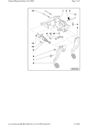
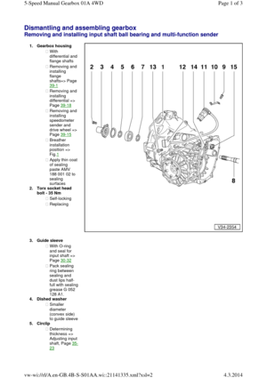
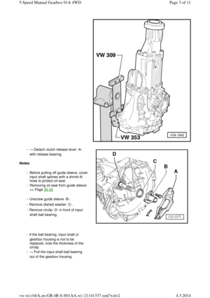
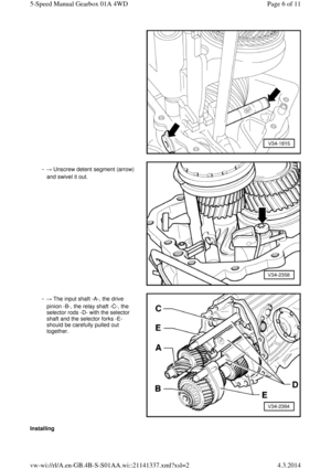
Dismantling and assembling gearbox Removing and installing input shaft ball bearing and multi-function sender 1.Gearbox housing ◆ With differential and flange shafts
◆ Removing and
installing
flange
shafts=> Page
39-1
◆ Removing and
installing
differential =>
Page 39-18
◆ Removing and
installing
speedometer
sender and
drive wheel =>
Page 39-15
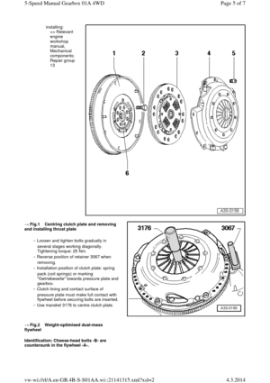
◆ Breather
installation
position =>
Fig.1
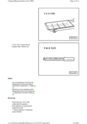
◆ Apply thin coat of sealing
paste AMV
188 001 02 to
sealing
surfaces
2.Torx socket head
bolt - 35 Nm
◆ Self-locking
◆ Replacing
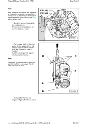
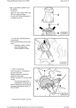
3.Guide sleeve ◆ With O-ring
and seal for
input shaft =>
Page 30-32
◆ Pack sealing
ring between
sealing and
dust lips half-full with sealing grease G 052
128 A1.
4.Dished washer
◆ Smaller
diameter
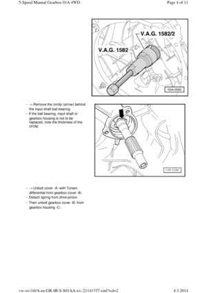
(convex side) to guide sleeve 5.Circlip
◆ Determining
thickness => Adjusting input shaft, Page 35-23 Page 1 of 35-Speed Manual Gearbox 01A 4WD4.3.2014vw-wi://rl/A.en-GB.4B-S-S01AA.wi::21141335.xml?xsl=2
Page 55 of 71
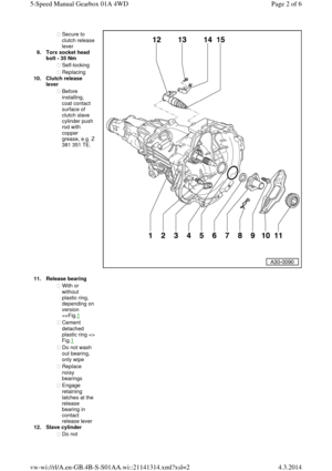
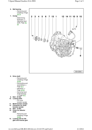
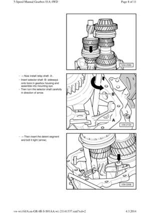
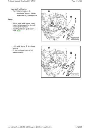
6.Ball bearing ◆ Removing and installing=>Page 34-74
7.Circlip
◆ Determining
thickness =>
Adjusting input
shaft, Page 35-23 8.Drive shaft ◆ Removing and installing=>Page 34-69
◆ Dismantling and assembling =>
Page 35-1
◆ Adjusting =>
Page 35-23
◆ Servicing input
shaft bearings
=> Page 35-1
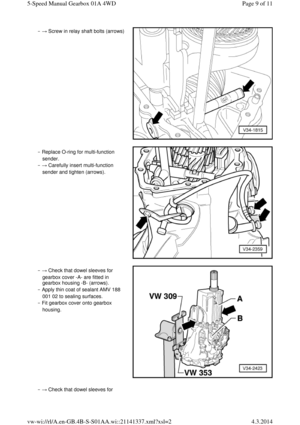
9.Bolt - 25 Nm
10.Locking plate
◆ For multi-
function sender
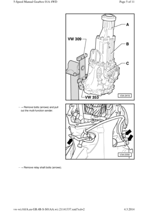
11.Multi-function sender 12.Connector for multi-
function sender
13.Bolt - 10 Nm
14.Cover for selector
shaft
◆ Removing and installing=>Page 34-98
15.Locking unit for 5th gear and reverse gear Page 2 of 35-Speed Manual Gearbox 01A 4WD4.3.2014vw-wi://rl/A.en-GB.4B-S-S01AA.wi::21141335.xml?xsl=2
Page 56 of 71
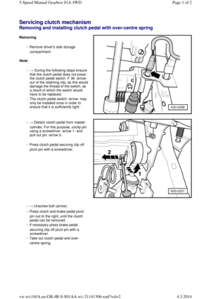
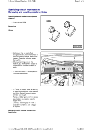
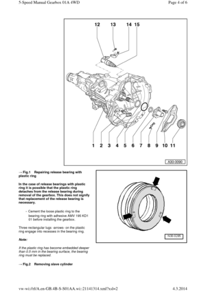
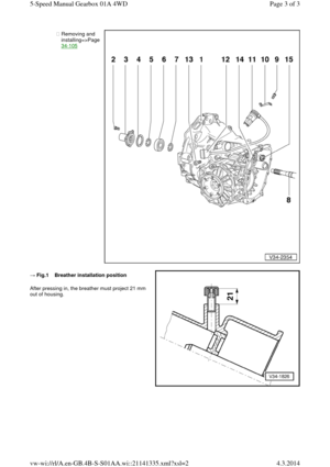
◆ Removing and installing=>Page 34-105 → Fig.1 Breather installation position After pressing in, the breather must project 21 mm
out of housing. Page 3 of 35-Speed Manual Gearbox 01A 4WD4.3.2014vw-wi://rl/A.en-GB.4B-S-S01AA.wi::21141335.xml?xsl=2

; Repair group 24
6.25 Nm
◆ Replace
7.Gasket
◆ Replace
8.25 Nm 9.Mounting ◆ Individual
parts of
mounting
of")

◆ Align
exhaust system so it is free of
stress =>
Page 26")


