Page 9 of 19

39-71
Installing
Installation is carried out in the reverse order,
when doing this note the following:
Note:
It is essential that the locking fluid remaining in
the threads in the drive flanges on the
transmission and rear final drive is cleaned out
after removing the driveshaft. Otherwise there
is a danger that the new bolts will seize when
they are screwed in and then shear if they have
to removed later.
The threaded holes can be cleaned with a
thread tap.
Replace the gaskets on the drive flanges
(remove backing foil and stick gaskets onto
drive flange; make sure that the surfaces are
free of grease).
To prevent imbalance, the flanges on the driveshaft -A- and on the
rear final drive -B- must be installed so that the factory markings (or
the markings made on removal) are in alignment (arrows). If a new driveshaft is being installed and the factory paint marking on
the rear final drive flange is no longer visible, the radial run-out at the
flange for the driveshaft must be measured Page 39
-73
, and the
paint marking on the driveshaft must be aligned with the marking on
Pa
ge 9 of 19 Driveshaft, servicin
g
11/19/2002 htt
p://127.0.0.1:8080/audi/servlet/Dis
play?action=Goto&t
yp
e=re
pair&id=AUDI.B5.TM03.39.9
Page 10 of 19
the flange. After removing the driveshaft from the rear final drive, the additional
balance disk (thick washer) that may be located between the lock
plate and the bolt head must not be reinstalled. Always replace all
flange bolts after disassembling. Replace driveshaft bolts (self-locking).
Pa
ge 10 of 19 Driveshaft, servicin
g
11/19/2002 htt
p://127.0.0.1:8080/audi/servlet/Dis
play?action=Goto&t
yp
e=re
pair&id=AUDI.B5.TM03.39.9
Page 11 of 19
39-72
- Adjust driveshaft after installing Page 39
-
75
.
- Align exhaust system free of stress.
Repair Manual, 2.7 Liter V6 5V BiTurbo
Engine Mechanical, Engine Code(s): APB, Repair Group 26; Removing and installing parts of exhaust system
Tightening torques
Component
Nm
Driveshaft to transmission
(output flange) 55
Driveshaft to final drive
(input flange) 55
Driveshaft center mounting to body 23
Heat shield for driveshaft to transmission 23
Cross member to body 25
Nuts for clamp 40
Pa
ge 11 of 19 Driveshaft, servicin
g
11/19/2002 htt
p://127.0.0.1:8080/audi/servlet/Dis
play?action=Goto&t
yp
e=re
pair&id=AUDI.B5.TM03.39.9
Page 12 of 19
39-73
Radial run-out at driveshaft flange and
marking, measuring
Special tools, testers and auxiliary items
Universal dial gauge bracket VW 387
Lifting tackle 2024 A
Dial gauge
M10 x 85 bolt
Note:
The radial run-out must always be measured
when the drive flange housing is removed.
Remove old paint marking and make new
marking.
If a new driveshaft is being installed and the
marking on the drive flange of the rear final
drive is no longer visible, the point of maximum
radial run-out must be measured with a dial
gauge and marked with paint.
The paint marking on the driveshaft is then
brought into alignment with this paint marking
Pa
ge 12 of 19 Driveshaft, servicin
g
11/19/2002 htt
p://127.0.0.1:8080/audi/servlet/Dis
play?action=Goto&t
yp
e=re
pair&id=AUDI.B5.TM03.39.9
Page 13 of 19
Page 39
-71
.
The radial run-out can be measured when the
rear final drive is installed, but the driveshaft
must be disconnected at the rear final drive.
Observe notes Page 39
-64
.
Pa
ge 13 of 19 Driveshaft, servicin
g
11/19/2002 htt
p://127.0.0.1:8080/audi/servlet/Dis
play?action=Goto&t
yp
e=re
pair&id=AUDI.B5.TM03.39.9
Page 14 of 19
39-74
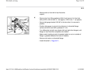
- Remove bolt on front left of rear final drive
support.
- Remove bar from lifting appliance 2024 A and secure it to free hole
with an M10 x 85 mm bolt -2-. Use approx. 5 M12 nuts -1- as spacers.
- Secure dial gauge bracket VW 387 to the bar when it is secured in
position.
- Position dial gauge on ground circumference in driveshaft flange
(arrow) and set to zero with a preload of 1 mm.
- Turn differential via both rear wheels (left and right drive flanges) until
flange on rear final drive completes one rotation.
- Make a paint marking at point of greatest radial run-out on outside of
flange (= greatest distance from axis of rotation).
- Remove old marks on driveshaft flange.
- Install driveshaft Page 39
-71
.
Pa
ge 14 of 19 Driveshaft, servicin
g
11/19/2002 htt
p://127.0.0.1:8080/audi/servlet/Dis
play?action=Goto&t
yp
e=re
pair&id=AUDI.B5.TM03.39.9
Page 15 of 19
39-75
Driveshaft, adjusting
Special tools, testers and auxiliary items
Adjustments should be carried out with care, because a badly adjusted
driveshaft is often the cause of vibration and droning.
Repair Manual, 2.7 Liter V6 5V BiTurbo Engine Mechanical, Engine Code(s): APB, Repair Group 26
Assembly appliance 3405
- Observe notes Page 39
-64
.
- If fitted, remove cross-piece below exhaust system.
- Remove rear section of exhaust system (rearward of exhaust pipe
clamp(s)): - Remove heat shields above driveshaft.
Pa
ge 15 of 19 Driveshaft, servicin
g
11/19/2002 htt
p://127.0.0.1:8080/audi/servlet/Dis
play?action=Goto&t
yp
e=re
pair&id=AUDI.B5.TM03.39.9
Page 16 of 19
39-76
- Loosen securing bolts of center driveshaft
mounting slightly.
Note:
Never fit assembly appliance onto balance plates. - Attach assembly appliance 3405 and tighten the plastic nuts.
- Remove securing bolts and shims from center mounting.
Parts catalog - Align center driveshaft mounting so that distance -a- is the same on left
and right.
- Measure -a- on both sides.
- Select shims from table.
Pa
ge 16 of 19 Driveshaft, servicin
g
11/19/2002 htt
p://127.0.0.1:8080/audi/servlet/Dis
play?action=Goto&t
yp
e=re
pair&id=AUDI.B5.TM03.39.9


 that may be located between the lock
plate and the bolt head must not be reinstalled.")


