Page 1 of 19
39-64
Driveshaft, servicing
Note:
Observe general repair instructions Page 00
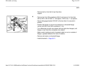
-
11
.
Do not bend the driveshaft more than 25 at the
central joint, otherwise the universal joint will be
damaged.
Only store and transport driveshaft extended.
No repair work can be carried out on the
driveshaft with the exception of removing,
installing and adjusting.
If the driveshaft is only detached at the
transmission or from rear final drive then the
driveshaft is to be tied-up or supported at the
constant velocity joint.
Before removing, mark the position of the rear
driveshaft joint in relation to the flange on the
rear final drive. Reinstall in the same position,
otherwise this can cause excessive imbalance,
bearing damage and droning noise.
If complaints are received (noises, vibrations), it
Pa
ge 1 of 19 Driveshaft, servicin
g
11/19/2002 htt
p://127.0.0.1:8080/audi/servlet/Dis
play?action=Goto&t
yp
e=re
pair&id=AUDI.B5.TM03.39.9
Page 2 of 19
is essential to check whether correct
adjustment of the driveshaft rectifies the fault
before replacing the driveshaft.
After removing the driveshaft from the rear final
drive, the additional balance disc (thick washer)
that may be located between the lock plate and
the bolt head must not be reinstalled.
Pa
ge 2 of 19 Driveshaft, servicin
g
11/19/2002 htt
p://127.0.0.1:8080/audi/servlet/Dis
play?action=Goto&t
yp
e=re
pair&id=AUDI.B5.TM03.39.9
Page 3 of 19
39-65
1 -
Rear final drive
2 -
Gasket
Always replacePull off backing foil, and stick self-adhesive
side of gasket to drive flange. Remove grease from drive flange
3 -
Constant velocity joint Maximum permissible angle of deflection
8
4 -
Lock plate
5 -
Hex socket head bolt, 55 Nm
Self-lockingAlways replaceThreads for bolts in drive flanges must
always be cleaned (e.g. with a thread tap)
Pa
ge 3 of 19 Driveshaft, servicin
g
11/19/2002 htt
p://127.0.0.1:8080/audi/servlet/Dis
play?action=Goto&t
yp
e=re
pair&id=AUDI.B5.TM03.39.9
Page 4 of 19
39-66
6 -
Universal joint
Maximum permissible angle of deflection
25
7 -
Shim
Determining thickness Page 39
-76
8 -
Hex bolt, 23 Nm
9 -
Driveshaft center mounting
10 -
Driveshaft
Adjusting Page 39
-75
11 -
Hex socket head bolt, 55 Nm
Self-lockingAlways replaceThreads for bolts in drive flanges must
always be cleaned (e.g. with a thread tap)
Pa
ge 4 of 19 Driveshaft, servicin
g
11/19/2002 htt
p://127.0.0.1:8080/audi/servlet/Dis
play?action=Goto&t
yp
e=re
pair&id=AUDI.B5.TM03.39.9
Page 5 of 19
39-67
12 -
Lock plate
13 -
Constant velocity joint
Maximum permissible angle of deflection
8
14 -
Gasket
Always replacePull off backing foil, and stick self-adhesive
side of gasket to drive flange. Remove grease from drive flange
15 -
Transmission
Pa
ge 5 of 19 Driveshaft, servicin
g
11/19/2002 htt
p://127.0.0.1:8080/audi/servlet/Dis
play?action=Goto&t
yp
e=re
pair&id=AUDI.B5.TM03.39.9
Page 6 of 19
39-68
Driveshaft, removing and installing
Special tools, testers and auxiliary items
Assembly appliance 3405
- Observe notes Page 39
-64
.
Removing
- If fitted, remove cross piece below exhaust
system.
- Remove rear section of exhaust system
(rearward of exhaust pipe clamp(s)):
Repair Manual, 2.7 Liter V6 5V BiTurbo
Engine Mechanical, Engine Code(s): APB, Repair Group 26
Pa
ge 6 of 19 Driveshaft, servicin
g
11/19/2002 htt
p://127.0.0.1:8080/audi/servlet/Dis
play?action=Goto&t
yp
e=re
pair&id=AUDI.B5.TM03.39.9
Page 7 of 19
39-69
Removing
- Remove heat shields above driveshaft.
- Remove heat shield for driveshaft from cover for Torsen differential
(arrows).
Note:
Only mark if the same driveshaft is to be reinstalled. - Check whether there is a factory marking (paint spots (arrows)) on the
driveshaft flange and the flange on the rear final drive. If not, mark the
position of the driveshaft flange -A- in relation to the rear final drive
(arrow -B-) with paint.
Pa
ge 7 of 19 Driveshaft, servicin
g
11/19/2002 htt
p://127.0.0.1:8080/audi/servlet/Dis
play?action=Goto&t
yp
e=re
pair&id=AUDI.B5.TM03.39.9
Page 8 of 19
39-70
- Loosen securing bolts on both driveshaft
flanges.
- Unscrew three upper securing bolts on each
driveshaft constant velocity joint.
- Loosen securing bolts of center driveshaft
mounting slightly.
Note:
Never fit assembly appliance onto balance plates.
Note:
Only transport and store driveshaft when extended. - Attach assembly appliance 3405 and tighten the plastic nuts.
- Remove securing bolts of flange to transmission and to rear final drive
as well as securing bolts of center driveshaft mounting.
- Slide driveshaft together toward rear final drive. Constant velocity joints
move along their axis.
- Guide out driveshaft with assembly appliance past transmission flange.
Pa
ge 8 of 19 Driveshaft, servicin
g
11/19/2002 htt
p://127.0.0.1:8080/audi/servlet/Dis
play?action=Goto&t
yp
e=re
pair&id=AUDI.B5.TM03.39.9


.
Note:
Only mark if the same drive")
